U.S. Pat. No. 8,641,526
USING INPUT FROM A MOUSE DEVICE TO CONTROL A VIDEO GAME VEHICLE
AssigneeWarmaging.net LLP
Issue DateOctober 5, 2012
Illustrative Figure
Abstract
Methods and systems for controlling vehicles within video games are described herein. A video game such as a vehicle-based combat game may have vehicles (such as airplanes) operating in a simulated three dimensional space. Users may partially control the direction of these vehicles using two-dimensional input devices by inputting a new direction for the vehicle to point and optionally a speed with which to pursue the new direction. Alternatively, a user may wish to engage in continuous banked turning of their vehicle to realistically simulate aspects of vehicle-to-vehicle combat. Rotation of the vehicle from its current direction to its new direction is controlled by an artificial intellect, which operates various control equipment of the vehicle to realistically simulate the path of the vehicle, based on whether a user has input a desired destination or a desired turn direction.
Description
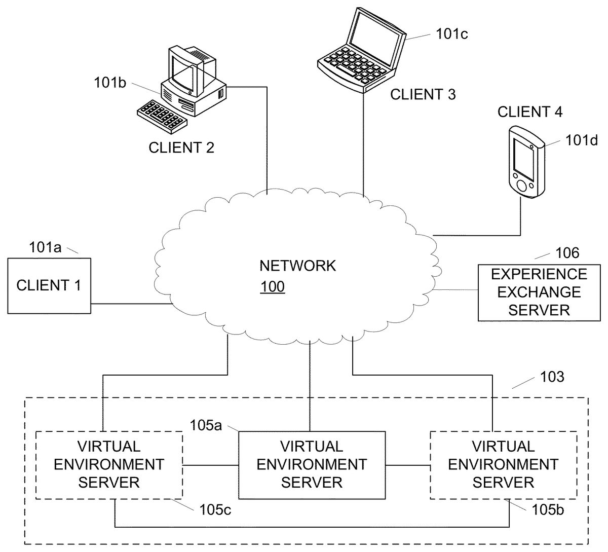
DETAILED DESCRIPTION In the following description of the various aspects, reference is made to the accompanying drawings, which form a part hereof, and in which is shown by way of illustration how various features described herein may be practiced. It is understood that other embodiments may be used and structural and functional modifications may be made. FIG. 1illustrates a network environment in which clients101may interact with virtual world servers105to provide a virtual world for users to access. Clients101may include a variety of devices including generic data processing device101a, personal computer (PC)101b, laptop, portable, or netbook computer101c, personal data assistant, mobile phone or device101d, a tablet device (not shown) and the like. Each of clients101may have a network adapter that allows clients101to connect to virtual world servers105through network100. In one example, network100may include an Internet Protocol (IP) based network, e.g., the Internet. Other networks may include cellular networks, cable networks, fiber optic networks, wireless networks, wired network and/or combinations thereof. Network100may further include one or more sub-networks such as wired or wireless local area networks (LANs), wide area networks (WANs), and the like. In one or more arrangements, virtual world servers105may be included in a virtual world server system103that includes multiple linked servers105. Using such a distributed system, servers105may be able to distribute load across each of server105. For example, if server105ais experienced high loads, some of the operations may be passed to either server105bor105cor both. Load may further be distributed based on user geography or on other predetermined bases. Alternatively, the virtual world may be hosted on a single server, e.g., virtual world server105a. Each of servers105may collectively generate and manage a single instance of the virtual world, or each server105a,105band105cmay provide independent instances of the world. An instance of a virtual world, as used herein, describes a stand-alone copy ...
DETAILED DESCRIPTION
In the following description of the various aspects, reference is made to the accompanying drawings, which form a part hereof, and in which is shown by way of illustration how various features described herein may be practiced. It is understood that other embodiments may be used and structural and functional modifications may be made.
FIG. 1illustrates a network environment in which clients101may interact with virtual world servers105to provide a virtual world for users to access. Clients101may include a variety of devices including generic data processing device101a, personal computer (PC)101b, laptop, portable, or netbook computer101c, personal data assistant, mobile phone or device101d, a tablet device (not shown) and the like. Each of clients101may have a network adapter that allows clients101to connect to virtual world servers105through network100. In one example, network100may include an Internet Protocol (IP) based network, e.g., the Internet. Other networks may include cellular networks, cable networks, fiber optic networks, wireless networks, wired network and/or combinations thereof. Network100may further include one or more sub-networks such as wired or wireless local area networks (LANs), wide area networks (WANs), and the like.
In one or more arrangements, virtual world servers105may be included in a virtual world server system103that includes multiple linked servers105. Using such a distributed system, servers105may be able to distribute load across each of server105. For example, if server105ais experienced high loads, some of the operations may be passed to either server105bor105cor both. Load may further be distributed based on user geography or on other predetermined bases. Alternatively, the virtual world may be hosted on a single server, e.g., virtual world server105a. Each of servers105may collectively generate and manage a single instance of the virtual world, or each server105a,105band105cmay provide independent instances of the world. An instance of a virtual world, as used herein, describes a stand-alone copy of the virtual world that does not interact with or depend on other instances of the virtual world. Depending on the processing load, a virtual world server system103may divide a plurality of users among multiple instances of the virtual world, each hosted on a different server, to reduce or alleviate overloading on a single server or prevent overpopulation. Each server105may be logical or physical, e.g., multiple logical servers may reside and be running on the same physical computing device/server, or servers may be physically separate devices.
FIG. 2illustrates an example client device200such as PC101b(FIG. 1) that may be used to access and interact with a virtual world provided by a virtual world server such as server105aofFIG. 1. Client device200may include a variety of components and modules including a processor217, random access memory (RAM)215, read only memory (ROM)213, databases201and203, client software205, output adapter211, input interface209and communication interface207. Software, databases, operating systems, and the like may be stored in nonvolatile memory206(e.g., a magnetic disk or solid state hard drive, or equivalent). Object database201may be configured to store data defining and otherwise associated with an object used by a user of device200to explore and interact with the virtual world. World database203, on the other hand, may be configured to store data for defining and generating the environment in which the objects exist. For example, world database203may store texture maps for rendering a floor or ground, walls, a sky and the like. In another example, world database203may store simulated environments, buildings, trees and other data defining animate or inanimate objects existing in the world, data defining computer controlled characters and the like. Each of database201,203may or may not be a conventional database, and instead may refer to data stored in a memory, accessed as needed by the client software. Data associated with an object or the virtual world may be communicated between client device200and a virtual world server using communication interface207. For example, object positions, attributes and status may be updated or environments may be changed by communicating such data through interface207. In an alternative embodiment, instead of or in addition to databases201,203, client device200may maintain a state of a user account as it interacts with one or more game servers, and client software205may render and represent the game environment on an output display based on the present account state. The state information may include, e.g., location, health, team, etc.
The world and the objects may be rendered by client software205and subsequently sent to output adapter211and display219. The client software205may, in one or more arrangements, be configured to generated three dimensional (3-D) models of the virtual world and components thereof as well as the object corresponding to a user. A user may control the object and interact with the world through input interface209using various types of input devices including keyboard223and mouse225. Other types of input devices may include a microphone (e.g., for voice communications over the network), joysticks, motion sensing devices and/or combinations thereof. In one or more arrangements, music or other audio such as speech may be included as part of the virtual world. In such instances, the audio may be outputted through speaker221. In some embodiments, the virtual world may be a graphical representation only, and objects in the virtual world may be renderings, as opposed to objects in an object oriented programming language.
Client software205, computer executable instructions, and other data used by processor217and other components of client device200may be stored RAM215, ROM213, nonvolatile memory206or a combination thereof. Other types of memory may also be used, including both volatile and nonvolatile memory. Software205may provide instructions to processor217such that when the instructions are executed, processor217, client device200and/or other components thereof are caused to perform functions and methods described herein. In one example, instructions for generating a user interface for interfacing with the virtual world server may be stored in RAM215, ROM213and/or nonvolatile memory206. Client software205may include both applications and operating system software, and may include code segments, instructions, applets, pre-compiled code, compiled code, computer programs, program modules, engines, program logic, and combinations thereof. Computer executable instructions and data may further be stored on some physical form of computer readable storage media (referred to herein as “computer memory”) including, e.g., electrically erasable programmable read-only memory (EEPROM), flash memory or other memory technology, CD-ROM, DVD or other optical disk storage, magnetic cassettes, magnetic tape, magnetic storage and the like.
Referring now toFIG. 3, a virtual world server300may be configured to generate and operate a massive multiplayer online game, such as virtual world or the like. Server300may include processor301, ROM303, RAM305, communication interface307, object position database309, world database311, user database313, and server software317. Object position database309may be configured to store position information for each object (e.g., based on commands to move a vehicle received from each client).
A world database311may store rules, algorithms and other data for interactions that are available in the world. For example, a manner in which a computer controller character moves or otherwise behaves may be defined in data stored in world database311. Additionally, item information may be defined in world database311so that items may not be modified by each client. In another example, world database311may store location information for non-object items and components. User database313, on the other hand, may be configured to store information describing a user controlling an object. For example, user database313may include account information, user preferences, one or more classes of user experience points and/or levels, payment information, user identification information, character definitions, state tables, and the like. Each of databases309,311,313may or may not be a conventional database, and instead may refer to data stored in a memory, accessed as needed by the server software.
Features described herein may be used with or in a variety of video games, including but not limited to, WORLD OF TANKS, WORLD OF WARPLANES, and/or WORLD OF WARSHIPS by WARGAMING.NET. Aspects described herein may also be used with other video games and are not limited to any one genre or implementation. Aspects described herein may be implemented in video game application software stored on a computer readable medium, e.g., storage201,203,205,206,213,215,309,311and/or313, and executable by a data processing device.
Various aspects of the disclosure provide features and capabilities that enhance game play by providing options through which users can develop strategies to play the video game. According to various aspects described herein, a video game may provide a graphically stimulated virtual world or virtual environment, in which the game takes place, referred to herein interchangeably as a virtual world and as a simulated environment of the video game. The simulated environment may have features similar to actual geographic locations or may have fictional, science fiction or fantasy-themed environments.
FIG. 4illustrates a block diagram of a video game software application401. Each block inFIG. 4illustrates a logical software module or function that performs an action, provides a capability or feature, implements an object, or performs some other aspect of the video game. When the video game software401executes on a data processing system such as a PC or game console, the modules operate collectively to provide a video game experience to a player. The modules illustrated inFIG. 4are illustrative only, and additional or different modules may be used. The same, additional or different modules may be executed in tandem on a server with which each client device is connected.
Video game software401may include, e.g., a game manager module402, which manages the overall operation of the video game and may be the initial module launched when the video game is executed. Video game software401may also include a network module403, which manages network games sessions. A network game session may include e.g., a co-operative campaign with other networked players, or other compartmentalized periods of game play involving players located at discrete network locations. A memory manager module409performs memory management during execution of the video game401. An input module404may receive and interpret user input via a game controller, keyboard, mouse, and the like, and provide the interpreted commands to game manager402, network module403, or other applicable module. UI module405may manage and control the user interface, including the display displayed on the video output device, interpreting input via the input module404, and providing audio output via audio module408.
Various software modules may operate with one or more classes or objects defined and used in the video game401. The classes and objects may be defined with reference to an object module410, and may include portions of executable software code and/or one or more data structures, depending on the object. Each object may be rendered and simulated in the virtual world in accordance with a physics engine407. Video game software401may include other software modules411as needed.FIG. 4illustrates one possible software architecture. Others may be used. Each module depicted inFIG. 4may communicate directly or indirectly with each other module, e.g., by passing objects, data, parameters, input, and output, etc.
A first class of in-game objects may define vehicles in the video game. A vehicle may be defined as any simulated inanimate object directly or indirectly controllable by or dependent on an in-game character and/or user/player. Illustrative vehicles may include airplanes, helicopters, tanks, ships (and/or submarines), battleships, and the like. Vehicles may have various attributes and functions that provide advantageous qualities to the vehicle during combat. For example, some vehicles might be fast with minimal firepower, whereas other vehicles may be slower but extremely powerful. Infinite variations of strength, speed, defense, and any other attribute are possible.
A second class of in-game objects may define characters in the video game. Characters may be defined by various attributes associated with the character, e.g., name, physical appearance, skills, etc. Skills may be defined based on a character's genre or task, e.g., ball turret gunners and pilots in the present example. A ball turret gunner may have skills such as aiming accuracy and aiming speed and a pilot may have skills that regulate the vehicle speed or precision of direction. Additional character attributes may include one or more other skills that can improve performance of the character or vehicle so as to enhance the strategic gaming experience such as firefighting skills, the ability to repair vehicles, the ability to perform aerial maneuvers, and the like. The second class of objects may further include munitions, equipment, and upgrades usable with one or more of the objects in the first class of game objects.
Object module410may provide an array of vehicles, vehicle components, characters and other equipment. Vehicles, vehicle components, characters and other equipment may be defined by one or more objects and instantiated during the game. Each object may have various attributes and functions and provide advantages and disadvantages based thereon. A vehicle component may refer to an upgradeable component of a vehicle, e.g., engine, payload, guns, etc.
FIG. 5Aillustrates a block diagram of an instance501of a character object within the second class of game objects. Object instance501has an object class505(Character). Instance501may acquire one or more attributes from the object class. Attributes507, when examined, define a state of the instance. In this example, the Character has the following attributes: Name511, Qualification512, Training Level513, and Competence514. A character may also have additional skill types509. Additional skill types may include Aerial Engagement skills515, Targeting skills516, and Maneuvering skills517. Other skill types, attributes, etc., may also or alternatively be used.
Each attribute may have a particular value. The attribute may have a default value inherited from the Qualification type512. For some attributes, a player may increase attribute value by allocating experience points, gained during gameplay, to the character. Increased attribute value enhances gameplay by improving performance of the vehicle containing the characters. For example, by allocating experience points to the pilot of an airplane, the Training Level513may be increased resulting in more accurate piloting by a vehicle containing that character, leading to improved vehicle performance during battle. Similarly, the effectiveness of the additional skill types is increased in accordance with the value of the skill. Thus, for example, an Offensive Maneuvering skill516value of 100% is proportionally more effective than a value of 50%. Increased offensive maneuvering effectiveness may result in better positioning of the aircraft for firing upon enemy vehicles during combat. By staffing a vehicle (one of the first classes of objects) with characters having improved attributes and skills, vehicle performance is maximized allowing for a more effective performance during game play. Vehicles may further be staffed or equipped with other objects of the second class of objects, e.g., munitions, equipment, and/or upgrades, to further improve vehicle performance.
In some embodiments, attributes might not be able to be changed. Qualification512may not be changed; for example, a pilot may not be retrained as a ball turret gunner. A character's Competence attribute514refers to their ability to operate a specific vehicle type; for example a specific type of aircraft such as the Kochyerigin TSh-1 airplane. Competence514may be changed by retraining the character to operate the same Qualification512on a different vehicle. Changing Competence514may result in a decreased Training Level513in the new vehicle. Additional experience points may be used to raise the Training Level513in the new vehicle. A character may eventually be associated with multiple competence attributes—one per vehicle the character has been associated with. In some embodiments, character training may further be limited based on a national origin of the in-game character, or based on some other designation. For example, a character said to be from Russia might not be permitted as crew in a vehicle originating from Japan.
FIG. 5Billustrates a block diagram of an instance551of a vehicle object within the first class of game objects. Object instance551has an object class555(Vehicle). Instance551may acquire one or more attributes557from the object class. Attributes557, when examined, define a state of the instance. In this example, object instance551is a Boeing P-12 and has attributes with values typical of fighter aircraft. Illustrative attributes may include Name561, Hit Points563, Mass565, Engine Power (h.p.)567, Wing Area569, Top Speed at Lowest Altitude571, Top Speed at Highest Altitude573, and Rate of Climb575. These attribute contribute to the vehicle's effectiveness in combat. Attribute types may also have an attribute value, which determines the effectiveness of the attribute function. For example, the Top Speed at Highest Altitude attribute573has a value of 283 km/h, which indicates how fast the vehicle can travel at the highest altitude of its service range. One or more of the attributes, alone or in combination, may be used to assign the vehicle to a subclass. In this example, vehicle551may be in a subclass of fighter aircraft referred to as “Light Fighters” based on hit points, speed, armor, etc. Other classes of fighter aircraft may include medium fighters, heavy fighters, attack planes, carrier-based planes, bombers, and scouts, among others. Subclass may be used to quickly identify to a user a general approximation of attributes associated with a vehicle without requiring the user to review each attribute in detail.
Vehicle attributes may be altered by adding or upgrading modules associated with a vehicle. A vehicle contains modules classes559. Each module class may contain one of a variety of module types appropriate to the module class. In one example, module classes may include Gun1577, Gun2579, Payload581, and Engine583. In another embodiment, modules may include airframe modules, bomb modules, and rocket modules. Additional585modules may be added to provide additional functions or otherwise modify vehicle attributes557. Within each class, a vehicle may be outfitted with one module type that falls within the class. For example, five increasingly powerful gun types may be available within the gun class. Similarly, there may be multiple payload types within the payload class. Adding or changing a module type alters vehicle attributes557based on the effectiveness of the newly installed module type. The vehicles physical appearance and/or flight characteristics may also be altered, based on the airplane model and module added. Thus, for example, if the Engine module583type Pratt & Whitney R-1340 Wasp is replaced by a more advanced module the Rate of Climb575attribute value may increase based on a rate of climb value associated with the more advanced module. An increased Rate of Climb value, in turn, may allow the vehicle to more quickly ascend into or out of an in-flight battle during game play, making the player more competitive against opponents and resulting in an enhanced gameplay experience for that player.
Acquiring Input from a Mouse Device to Control a Video Game Vehicle
According to some aspects, the user may be in control of a vehicle (e.g., an aircraft) and tasked with performing one or multiple game objectives as part of the game play. Example game objectives may include engagement in combat with a member or members of an opposing team, targeting and firing upon an opposing team's base or territory, and/or performing a sequence of vehicle maneuvers. A current example of a vehicle may be a fixed-wing aircraft (although rotating wing, vertical thrust, and other types of aircraft may also be simulated). Various aspects of the disclosure provide features and capabilities that enhance game play through facilitating control of the movement of the vehicle based on user input from a mouse (or other two dimensional input) device. Such aspects may allow a user to more rapidly learn how to control and maneuver vehicles within the virtual world and may enable the user to better focus on completion of game objectives. Although not limiting, attention is given herein to vehicles capable of movement within three dimensions, e.g., aircraft, spacecraft, submarines, etc., rather than vehicles that move in two dimensions, such as cars and boats. Other control methods may also be used.
Realistic and accurate pursuit of a new direction of travel may be performed by rotation of the vehicle along one or more axes through the vehicle's center of mass.FIG. 6illustrates the conventional axes of rotation. Rotation along axis601, which intersects the vehicle610through its nose604and tail605substantially parallel to the ground, is conventionally called “roll.” Rotation along axis602, which intersects the vehicle610laterally and substantially parallel to wings606and607, is conventionally called “pitch.” Rotation along axis603, which intersects the top608and bottom609of the vehicle610substantially perpendicular to the ground is conventionally called “yaw.”
Once the game begins or a user is given full control of the vehicle by the video game software, the user may provide directional input using a mouse or other two dimensional input device (collectively referred to herein as a mouse). The input may be representative of a new direction of vehicle travel that the user wishes the vehicle to pursue. That is, the use may use a mouse to place a cursor at a position on the screen that indicates either where the user wants to go, specifically, or a general direction the user wants to travel. Input may be provided using a joystick, in which case conventional and known flight control techniques may be used.
In some embodiments a user might only have a mouse and keyboard available to provide input to the game. In such an embodiment, the input is provided to the video game software by movement of the mouse225located proximately to the client device200. For example, if the user wants the vehicle to pursue a course toward an object currently off the left side of the vehicle and at a lower altitude than the vehicle (from the viewpoint of the user), she may drag the mouse diagonally to the left and toward her body (resulting in a cursor moving down and town the left on a display screen) to indicate that she wishes the vehicle to bank left through a combination of roll and yaw, as well as pitch the vehicle's nose below the horizon. This input is provided to the input module404, which either alone or in combination with other modules of the video game software401performs various calculations regarding the movement of the vehicle as further described below.
With reference toFIG. 7A, a sample video game display may include a vehicle701controllable by a user, one or more targets702(e.g., ground-based and/or airborne), one or more friendly entities715, chat window716, a directional input indicator/cursor703(e.g., a mouse pointer) that may move correspondingly to mouse input, a targeting reticle704, and a visual input cue707. Input indicator may alternatively be displayed as a small circle, square, or other shape, and may be colored, e.g., green, for easy visual identification. Targets may be displayed with differing visual cues, e.g., a circle to indicate an enemy airplane, and a diamond to indicate a ground target. Directional input indicator703allows the user to input a desired direction of travel. As further described below, the desired direction of travel may be absolute, namely, based on a specific chosen destination, or relative, that is, indicating a change in direction a present heading. In some aspects, the directional input indicator may be a simple shape such as a pointer, arrow, circle, square, rectangle, or ellipse, but according to other aspects may be other symbols or groupings of symbols capable of illustrating to the user an inputted destination or direction of travel, as further described below.
Targeting reticle704serves two purposes in the present example. Indicator704shows the user the instant orientation of the vehicle701relative to the game environment. In other words, indicator704shows where the nose of vehicle701is pointed at any given moment in time. In some embodiments, indicator704may be a targeting reticle, usable for determining plane orientation with respect to targets. In other embodiments, indicator704may be an artificial horizon indicator, which not only indicates an instantaneous direction of travel, but also a plane's orientation to a horizon line in the simulated game environment. In other embodiments both a targeting reticle and an artificial horizon may be used and/or may be displayed on the display screen, as desired. When reticle704is not a targeting reticle, indicator704may be overlapping with a targeting reticle for a weapon (such as a gun) of the vehicle. In other aspects, the targeting reticle may be indicator704. Targeting reticle704also indicates where gunfire from aircraft vehicle701will be targeted, if the user provides input to fire the aircraft's weapon systems.
Visual input cue707serves multiple purposes as well. First, cue707provides a visual indication to the user identifying a region of the screen in which fine tuning directional input may be provided. Second, cue707divides the screen into two discrete input areas: a region inside cue707, and a region outside cue707. When input cursor703is within the region defined by cue707, user input may be interpreted as the user identifying a specific destination, also referred to as destination-based control. Stated differently, when the user places input cursor703at a location within cue707, the software may provide control inputs to vehicle701to cause vehicle701to turn as needed to result in a direction of travel towards the location identified by input cursor703. When the user places input cursor703outside cue707, input is analyzed based on directional-based control. Directional-based control refers to the software providing control inputs to vehicle701to cause vehicle701to turn based on the location of cursor703relative to the position of reticle704. The vehicle may continue to turn based on a location of cursor703until cursor703is brought back within the confines of cue707. The rate of turn may further vary based on how far cursor703is located on screen from reticle704. In some embodiments, visual cue707might not be displayed. In such a case, cue707is merely an unseen boundary between the two input regions.
In some embodiments, a user may dynamically configure a size and/or shape of cue707, e.g., based on a user preference to control a vehicle's destination versus direction. Users may prefer destination-based control when targeting a stationary target, such as an immovable ground target, and therefore make cue707larger. Users may prefer directional-based control when targeting moving targets, such as enemy aircraft, ground vehicles, moving battleships, etc., and therefore made cue707smaller.
Using this dual mode input, a user can decide whether to control an airplane by identifying a destination or a direction, as desired. Users can see the direction of travel resulting from the input when in destination-based control, which reduces the risk of erroneous input and reduces the risk of overcorrecting.
The input indicator703and reticle704may overlap after vehicle701has completed its course alteration to a new direction as input by the user within cue707. Furthermore, assuming no additional mouse movement by the user, the distance between indicator704and directional input indicator703may decrease as the vehicle rotates towards the direction input by the user. Of course, if the user inputs a new desired direction of travel while the vehicle is already rotating to a direction previously inputted, the vehicle may begin to pursue that new direction immediately upon receiving the input.
In addition to control of the direction of the vehicle, in some embodiments the user may partially control a speed of rotation with which the vehicle completes its rotation to the new direction of travel. According to some aspects, the speed of rotation may be controlled by increasing or decreasing the distance of the directional input indicator703from reticle704. When indicator703is within cue707but near the boundary of cue707, a speed of rotation may be faster than when indicator703is nearer to reticle704. When indicator703is outside cue707, rotation speed may increase as indicator703moves farther away from cue707. For example, moving input indicator703a small amount outside cue707may result in a gentle continuous yaw, pitch and/or roll toward the inputted direction, useful for making small adjustments to the vehicle in preparation for firing upon an enemy base. Moving input indicator703a larger amount away from cue707may result in a steep continuous movement toward the inputted direction, which may be necessary when offensively or defensively maneuvering against another aircraft. The speed of rotation may be limited to a predetermined maximum value, regardless of distance between rotational indicator and the center of the display, by fixed or variable characteristics of the character object controlled by the user (e.g., the type of vehicle being flown), the vehicle object controlled by the user, or as characteristics of the game map or session in which the vehicle object is operating. Other control inputs may also affect a speed of rotation, e.g., using a plane's flaps, turbo boost, turning off the plane's engine, and/or rolling the plane, among others.
With reference toFIG. 7B, one or more rotational speed indicators705may optionally be shown on the display screen to assist the player in understanding distance of indicator703from indicator704while controlling the vehicle701. As one example, the rotational speed indicator may be a line705connecting the center of the screen with the directional input indicator703. As another example, the rotational speed indicator may be represented using opacity, color, or gradient of a shape, such as an arrow, indicating the direction of the rotation. In some aspects, this shape may be the directional input indicator.
FIG. 7Cillustrates vehicle701in a steep turn resulting from the user having moved input indicator703outside of boundary707(not shown). The system, however, indicates to the user that indicator703is outside boundary707by including an arrow709within indicator703. Arrow709provides visual feedback to the user that the system is in direction-based control mode, rather than destination-based control mode. Arrows720indicate a relative direction of two nearby airplanes. Whether the airplanes are friend or foe may be further indicated by a color of the arrows, e.g., green for friend, red for foe, or a third color representing an airplane in pursuit.
When the user returns indicator703within boundary707, as the vehicle completes its rotation to the new direction of travel, the speed of rotation may decrease to realistically portray vehicle motion to the user. Accordingly, the rotational speed indicator705(or indicator703) may change in size, shape, opacity, gradient, or color, as illustrative examples, to indicate to the user that the vehicle's speed of rotation is declining.
In some aspects, the rate of movement of the directional input indicator may be partially influenced by a mouse sensitivity setting. The mouse sensitivity setting may be provided either by any of the various modules of video game software401or the operating system running the video game software. A decrease in the mouse sensitivity may result in requiring an increased amount of actual movement of the mouse device to achieve the same movement of the directional input indicator on the display. Similarly, an increase in mouse sensitivity may result in a decreased amount of actual movement of the mouse device required to achieve the same movement of the directional input indicator on the display. Customizable user control settings may also be present and influencing upon the movement of the directional input indicator. As one example, the user may select an “inverted” mode reversing the input directions along the z-axis. Where a user using a non-inverted mode may push the mouse away from them to indicate a desire for the vehicle to pitch its nose above the horizon, a user using the inverted mode may pull the mouse toward them to indicate a similar desire. Other user control settings may be provided, either by the video game software or any of its modules to enable the user to customize various aspects of how the input is processed.
With further reference toFIG. 7A-7D, various aspects of the directional input indicator and rotational speed indicator as they pertain to the rotation of the vehicle are now described. In this illustrative situation, a user is controlling a vehicle701, and tasked with firing upon a target702.FIG. 7A-Dshow movement of vehicle701based on input from the user using a mouse device. InFIG. 7A, when viewed from behind vehicle701, target702is positioned to the left and well ahead of the nose of vehicle701. InFIG. 7B, the user initially moves the mouse away and to the right, relative to the user's body (assuming a right-handed user). Rotational speed indicator705(here, a line of varying length) is displayed based on the distance the user has dragged the mouse device (and the directional input indicator). The system controls the vehicle701using destination based control. InFIG. 7C, the user banks hard left, by moving the mouse to the left so that indicator703is outside boundary707. The system now controls the plane in continuous rotation in direction-based control. InFIG. 7Dthe user has moved the indictor703back within boundary707, and vehicle701has settled into a straight line path toward target702.
According to some aspects, some game play situations may necessitate a vehicle controlled by the user to engage in continuous rotation. For example, in a game where two or more fixed-wing aircraft engage and pursue each other, sometimes called air combat maneuvering or “dogfighting,” circling constantly in air may be an attacking or defending tactical maneuver. Given no other input, a vehicle in continuous rotation will constantly rotate in a circle around a fixed point. The location of the fixed point is dependent on the rate of rotation and direction of rotation of the vehicle from the mouse input provided by the user. Such continuous rotation may occur while in directional-based input mode, until the user moves the input indicator703back within cue707.
According to some aspects, cue707may be defined by a predetermined area of the display, or beyond a predetermined distance from an initial or default position, e.g., from reticle704. InFIG. 8A, Cue807represent the boundary between destination-based control area801and direction-based rotation areas802and805. Cue707may or may not be visible on the display screen. The location and visibility of boundary807may be fixed for all modes of game play, or may be variable depending on, as illustrative examples, global or local user preferences, type of vehicle controlled, attribute of vehicle controlled, attribute of character controlled, or defined based on game play or some other dynamic. Of course, boundary lines need not be shown on the display. When the directional input indicator703is positioned in destination-based rotation area801, the vehicle may rotate as described above using destination-based control. However, if the user moves the directional input indicator703to direction-based rotation area802or805, continuous rotation in the respective direction may begin, based on the relative location of input indicator703.
Directional input indicator703may change appearance to notify the user whether destination-based or direction-based input mode is active. For example, directional input indicator703may change from a circle to a small arrow (or a small arrow within a circle, or some other visual cue), or vice versa. To end continuous rotation, the user may provide new input to move the directional input indicator703from rotation area802or805into rotation area801. Directional input indicator703may revert to an original appearance or presentation to notify the user that direction-based rotation has ended.FIG. 8Bshows an alternative embodiment having a circular boundary cue813(e.g., a larger version of visual cue707) between destination-based rotation area811and direction-based rotation area812. In such embodiment, the user may move the directional input indicator703from rotation area811to rotation area812to begin continuous rotation of the vehicle using direction-based input. Other alternative arrangements of the boundary, such as having an ellipsoidal, square, or rectangular shape, may also be used.
The directional input, or direction of rotation, and the speed of rotation can be said to form a motion vector. To move the vehicle in accordance with this motion vector, data elements comprising this motion vector are transmitted to an artificial intellect (AI) engine. This AI may be distributed among various modules within video game software401, operating alone or in connection with world game server300. Of course, it may also be centralized to any individual module or component within video game software401. Other input data may also be transmitted to the artificial intellect. Other input data may include, as illustrative but non-exhaustive examples, the speed of the vehicle relative to the ground, or indicators of damage to the vehicle caused by collisions with in-game objects or successful hits by opposing players.
As mentioned above, the motion vector along with the other input data may form the basis of various calculations regarding the movement of the vehicle. These calculations may result in the required roll, pitch, and yaw of the vehicle in three-dimensional space necessary to effect the desired movement of the vehicle in accordance with the motion vector. The AI then operates the vehicle's simulated control equipment in accordance with a realized flight-model and the combination of preset characteristics and variable characteristics of the vehicle in order to perform a maneuver. For example, this control equipment may include flaps, ailerons, elevators, control vanes, rudders, and so on. Vehicle characteristics may include those visible to the player, such as mass or engine power, as well as those not visible to the player, such as airfoil design, air temperature, and/or air pressure. Vehicle characteristics may also be dependent on game play rules or attributes of the video game, such as the particular map or battle mode.
According to some aspects, once the rotation of the vehicle is accomplished, the AI may automatically “level out” the vehicle. For example, if the vehicle is a fixed-wing aircraft, the AI may operate the vehicle's control equipment so that the wings of the aircraft will become level. As a result, after rotation of the aircraft is completed, the aircraft will travel in a straight line in the direction displayed by the up-to-the-minute indicator.
With reference toFIG. 9, software and/or hardware may perform a method for controlling a vehicle using two modes of input: destination-based input and direction-based input. Initially, in step901, the software receives mouse-based input from the user (other two-dimensional input devices may be used). As shown inFIG. 8B, when a user provides mouse input to alter a course of vehicle, mouse pointer703will be positioned either within destination-based input area811or direction based input area812. In step903the system determines which of the two areas mouse pointer703is in, and proceeds accordingly. If mouse pointer703is in destination based area811, then in step905the system determines the location identified by mouse pointer703and calculates the necessary control inputs on simulated airplane701to alter course of airplane701to result in a flight heading toward the destination identified by mouse pointer703. In step907the system applies the calculated inputs on simulated airplane701. In step909the system may gradually reduce the inputs to prove a smooth transition back to straight and/or level flight toward the destination, so as to avoid a jerky motion as the user is viewing the display screen. Once the plane has returned to straight and/or level flight, the method ends until the user provides subsequent mouse input.
If the user moves the mouse until point703is in direction-based control area812, then in step911the system calculates a relative direction based on the location of mouse pointer703relative the directional vector of travel of the airplane701. In step913the system may magnify or reduce the calculated control inputs based on the distance of mouse point703from reticle704. For example, a user moving pointer703farther away from reticle704may indicate a desire to turn faster than when pointer703is closer to the boundary813between regions811and812. In step915the system applies the control inputs to simulated plane701to turn in the desired direction. In step917the system determines whether the user has moved pointer703out of region812and back into region811. If so, the method returns to step905to handle the destination based input as described above. If not, the method returns to step911to continue direction-based control based on a then current position of mouse pointer703.
FIG. 10provides an illustrative example of how movement of the vehicle may occur as a result of directional based control flight calculations. In step1001, the player provides input using the mouse representing a new motion vector the player wishes the vehicle to pursue (e.g., using direction-based input). In step1002, other input data is acquired (e.g., the speed of the vehicle relative to the ground, or indicators of damage to the vehicle caused by collisions with in-game objects or successful hits by opposing players). In step1003, the aggregated data is transmitted to the artificial intellect. In step1004, the artificial intellect calculates the optimal roll, pitch, and yaw rotations for the vehicle. In step1005, the artificial intellect determines, based on the user input, if continuous rotation is desired. If not, the artificial intellect operates in step1006the vehicle control equipment to achieve the calculated rotations from step1004. If continuous rotation is desired, however, the artificial intellect operates the vehicle control equipment in step1007to achieve the continuous rotations until new input ending continuous rotation mode is provided by the user.
It will be appreciated that steps of the above-described methods may be rearranged, altered, removed, or split into more details or levels of granularity. The specific implementation details are secondary to the ability to provide users both directional and destination based control. For example, in one alternative embodiment, the entire screen may be a destination based input area. However, any time the user moves the mouse, the destination may reset to the new mouse location. Thus, as an airplane is turning, the user may continue to drag the mouse, in essence “fighting” against the system as it slowly moves the mouse pointer703toward reticle704as the plane turns toward the last identified destination.
The present aspects have been described in terms of preferred and exemplary embodiments thereof. Numerous other embodiments, modifications and variations within the scope and spirit of the appended claims will occur to persons of ordinary skill in the art from a review of this disclosure.
Claims
- One or more non-transitory computer readable media storing instructions that, when executed by a data processing device, cause the data processing device to: render a simulated three dimensional graphical environment for output to a display screen;control a moving vehicle within the three-dimensional graphical environment based on user input controlling a location of a two-dimensional input device;determining whether the location is within one of a first input area of a display screen and a second input area of the display screen;responsive to determining the location is within the first input area of the display screen, using destination-based control to alter a course of the vehicle to a heading in line with a destination identified by the location of the two-dimensional input device;and wherein the first input area consists of the interior area of a circle around a targeting reticle associated with the vehicle, and the second input area consists of a portion of the display screen outside the circle.
- The computer readable media of claim 1 , wherein the vehicle is an airplane.
- The computer readable media of claim 1 , wherein the vehicle is a tank.
- The computer readable media of claim 1 , wherein the vehicle is a battleship.
- One or more non-transitory computer readable media storing instructions that, when executed by a data processing device, cause the data processing device to: render a simulated three dimensional graphical environment for output to a display screen;control a moving vehicle within the three-dimensional graphical environment based on user input controlling a location of a two-dimensional input device;determining whether the location is within one of a first input area of a display screen and a second input area of the display screen;responsive to determining the location is within the first input area of the display screen, using destination-based control to alter a course of the vehicle to a heading in line with a destination identified by the location of the two-dimensional input device;and responsive to determining the location is within the second input area of the display screen, using direction-based control to alter the course of the vehicle in a direction identified by the location of the two-dimensional input device without an identified destination, wherein the first input area consists of the entire display screen.
- The computer readable media of claim 1 , wherein the direction is based on a location of the two-dimensional input device relative to a targeting reticle of the vehicle.
- The computer readable media of claim 1 , wherein the destination-based control comprises applying a smoothing function to control inputs as the vehicle approaches the identified destination.
- The computer readable media of claim 6 , wherein the destination-based control comprises altering a turn rate based on a distance of the location of the two-dimensional input device from the targeting reticle.
- A method comprising: rendering, by a processor, a simulated three dimensional graphical environment for output to a display screen;controlling a moving vehicle within the three-dimensional graphical environment based on user input controlling a location of a two-dimensional input device;determining whether the location is within one of a first input area of a display screen and a second input area of the display screen;responsive to determining the location is within the first input area of the display screen, using destination-based control to alter a course of the vehicle to a heading in line with a destination identified by the location of the two-dimensional input device;and responsive to determining the location is within the second input area of the display screen, using direction-based control to alter the course of the vehicle in a direction identified by the location of the two-dimensional input device without an identified destination: wherein the first input area consists of the interior are of a circle around a targeting reticle associated with the vehicle, and the second input area consists of a portion of the display screen outside the circle.
- The method of claim 9 , wherein the vehicle is an airplane.
- The method of claim 9 , wherein the vehicle is a tank.
- The method of claim 9 , wherein the vehicle is a battleship.
- A method comprising: rendering, by a processor, a simulated three dimensional graphical environment for output to a display screen;controlling a moving vehicle within the three-dimensional graphical environment based on user input controlling a location of a two-dimensional input device;determining whether the location is within one of a first input area of a display screen and a second input area of the display screen;responsive to determining the location is within the first input area of the display screen, using destination-based control to alter a course of the vehicle to a heading in line with a destination identified by the location of the two-dimensional input device;and responsive to determining the location is within the second input area of the display screen, using direction-based control to alter the course of the vehicle in a direction identified by the location of two-dimensional input device without an identified destination, wherein the first input area consists of the entire display screen.
- The method of claim 9 , wherein the direction is based on a location of the two-dimensional input device relative to a targeting reticle of the vehicle.
- The method of claim 9 , wherein the destination-based control comprises applying a smoothing function to control inputs as the vehicle approaches the identified destination.
- The method of claim 14 , wherein the destination-based control comprises altering a turn rate based on a distance of the location of the two-dimensional input device from the targeting reticle.
- A method comprising: receiving user input identifying a location of a two-dimensional input device;determining whether the location is within one of a first input area of a display screen and a second input area of the display screen;responsive to determining the location is within the first input area of the display screen, using destination-based control to alter a course of a vehicle in a simulated three dimensional environment depicted on the display screen based on a destination identified by the location of the two-dimensional input device;responsive to determining the location is within the second input area of the display screen, using direction-based control to alter a course of the vehicle based on a direction identified by the location of the two-dimensional input device;receiving user input defining the first input area and the second input area;and adjusting the size of the first input area and the second input area based on the received user input.
- A system, comprising: a processor, and memory storing instructions that, when executed the processor, configure the data processing device to: divide a user interface displayed on a display screen into a first input area and a second input area, wherein said first input area consists of a region within a circle around a targeting reticle displayed on the display screen, and the first input area consists of a region outside the circle;receive user input positioning a mouse on the display screen;determine whether a location of the mouse is within one the first input area of a display screen and a second input area of the display screen;responsive to determining the mouse location to be within the first input area, initiate a destination-based control mode to alter a course of an airplane in a simulated three dimensional environment depicted on the display screen based on a destination identified by the mouse location, wherein the destination-based control mode comprises applying a smoothing function as the vehicle approaches the identified destination;and responsive to determining the mouse location is within the second input area of the display screen, initiate a direction-based control mode to alter the course of the airplane based on a relative direction of the mouse location from a targeting reticle.
Disclaimer: Data collected from the USPTO and may be malformed, incomplete, and/or otherwise inaccurate.