DETAILED DESCRIPTION OF THE INVENTION The particular embodiment described below and illustrated byFIGS. 2 and 3serves to further illustrate the invention, to provide those of ordinary skill in the art with a complete disclosure and description of the devices claimed herein, and is not intended to limit the scope of the invention. For example, the additional controls are described below as two paddle levers but the term “control” as used in the claims, unless otherwise made clear in the claim, refers to paddle levers as well as other controls such as buttons, analogue control sticks, bumpers, and triggers. The game controller10according to the present invention is illustrated inFIGS. 2 and 3. The front of the game controller10ofFIGS. 2 and 3is the same as a conventional controller1, as illustrated inFIG. 1and as discussed above. Therefore, where appropriate the same reference numerals have been used to indicate the features of the controller according to the present invention10that are identical to the features of a conventional controller1. Game controller10differs from the conventional controller1in that it additionally comprises two paddle levers11located on the back of the controller. The paddle levers11are vertically orientated with respect to the controller10and are positioned to be operated by the middle fingers of a user12, as shown inFIG. 3. In one embodiment the paddles11are formed from a thin flexible material such as a plastics material for example polyethylene. Preferably, the paddles11are less than 10 mm thick, but may be less than 5 mm thick, and more preferably are 3 mm thick or less. The paddles11are inherently resilient, which means that they return to an unbiased position when not under load. A user may displace or depress either of the paddles11by engaging an outer surface thereof; such displacement causes the paddle11to activate a switch mechanism mounted within the body of the ...
DETAILED DESCRIPTION OF THE INVENTION
The particular embodiment described below and illustrated byFIGS. 2 and 3serves to further illustrate the invention, to provide those of ordinary skill in the art with a complete disclosure and description of the devices claimed herein, and is not intended to limit the scope of the invention. For example, the additional controls are described below as two paddle levers but the term “control” as used in the claims, unless otherwise made clear in the claim, refers to paddle levers as well as other controls such as buttons, analogue control sticks, bumpers, and triggers.
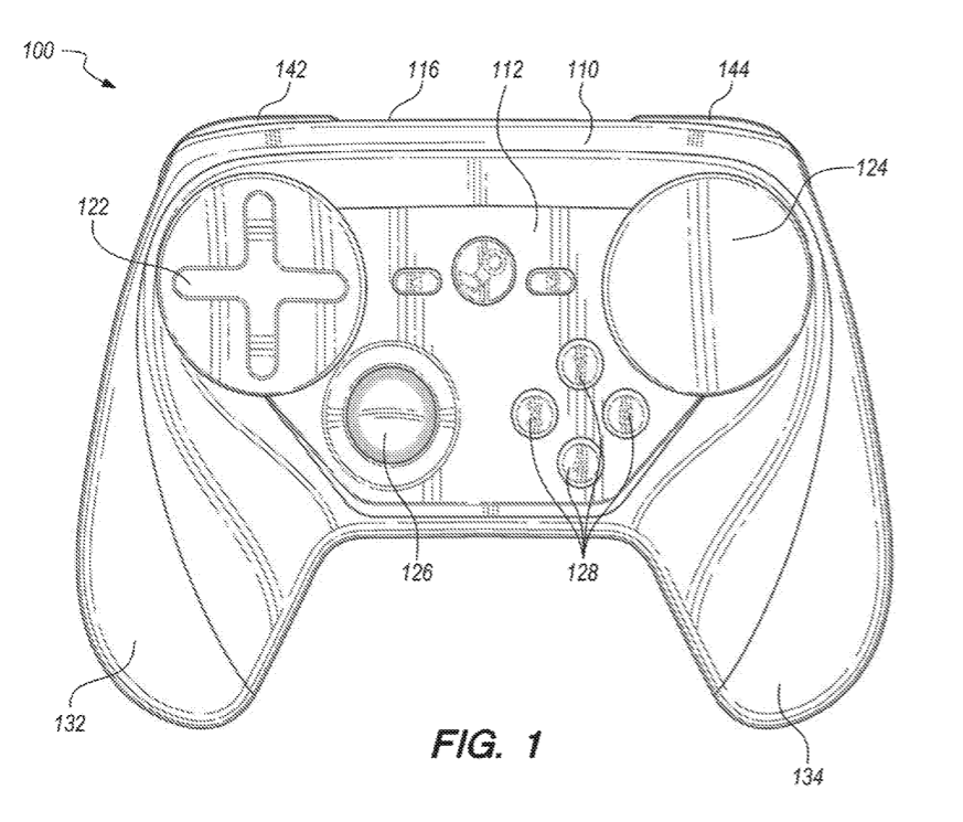
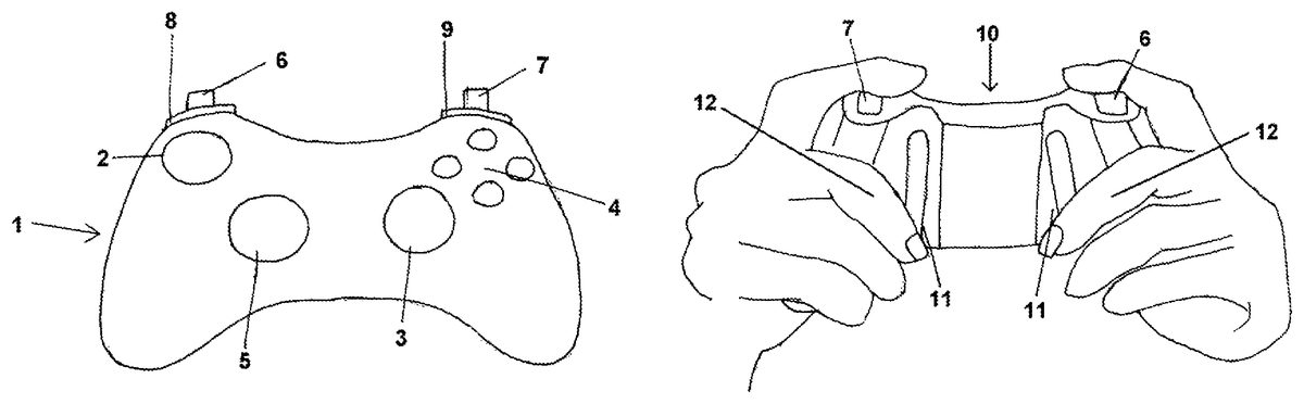
The game controller10according to the present invention is illustrated inFIGS. 2 and 3. The front of the game controller10ofFIGS. 2 and 3is the same as a conventional controller1, as illustrated inFIG. 1and as discussed above. Therefore, where appropriate the same reference numerals have been used to indicate the features of the controller according to the present invention10that are identical to the features of a conventional controller1.
Game controller10differs from the conventional controller1in that it additionally comprises two paddle levers11located on the back of the controller. The paddle levers11are vertically orientated with respect to the controller10and are positioned to be operated by the middle fingers of a user12, as shown inFIG. 3.
In one embodiment the paddles11are formed from a thin flexible material such as a plastics material for example polyethylene. Preferably, the paddles11are less than 10 mm thick, but may be less than 5 mm thick, and more preferably are 3 mm thick or less.
The paddles11are inherently resilient, which means that they return to an unbiased position when not under load. A user may displace or depress either of the paddles11by engaging an outer surface thereof; such displacement causes the paddle11to activate a switch mechanism mounted within the body of the controller10. The paddles11are mounted within recesses located on the case of the controller10; and are disposed in close proximity to the outer surface of the controller body. In this way a user may engage the paddles11with the tips of the fingers, preferably the middle fingers, without compromising the user's grip on the controller10. While the example shows the paddles11engaged by the middle fingers, they could also be engaged by the index, ring, or little fingers. The index fingers may also engage trigger style controls mounted on the top edge of the controller10while the thumbs may be used to activate controls on the front of the controller10.
The paddles11are elongate in shape and substantially extend in a direction from the top edge to bottom edge of the controller10. In one embodiment the paddles are orientated parallel with each other. In an alternative embodiment the paddles are orientated such that they converge towards the top edge with respect to each other. This elongate shape allows a user to engage the paddles with any of the middle, ring, or little finger; it also provides that different users having different size hands can engage with the paddles in a comfortable position thereby reducing the effects of prolonged or repeated use such as repetitive strain injury.
In one embodiment, the paddle levers11replicate the functions of two of the four buttons4located on the front of the controller10and thereby allow a user to operate the functions of the relevant buttons using his or her middle fingers12, without the need to remove either of his or her thumbs from the left or right thumb stick2,3. In alternative embodiments a paddle lever11may activate a new function not activated by a control on the front or top edge of the controller10.
It is envisaged that the paddles11could be fitted to an existing controller10. In such embodiments the paddles would be mounted on the outer surface of the controller body by means of a mechanical fixing such as a screw or bolt or alternatively bonded or welded to the controller body by adhesive or other suitable means. A switch mechanism would be mounted within the controller in vertical registry with a portion of each paddle. A portion of the switch mechanism may extend through the controller body and be disposed in close proximity or in contact with an innermost surface of the paddle11.
In alternative embodiments it is envisaged that the paddles11would be integrally formed with the controller body, the paddles11being configured to be resilient and flexible such that they can be depressed by a user to activate a switch mechanism. This could be achieved by moulding the controller body to have a U-shaped slot extending through the controller body; alternatively a U-shaped slot could be cut into the controller body after the moulding process.
Preferably, the paddles11would comprise a raised outermost surface with respect to the surrounding area such that a user may locate the paddles11. This may be achieved by moulding the paddle such that is thicker than the surrounding area. It will be recognised that as used herein, directional references such as “top”, “bottom”, “front”, “back”, “end”, “side”, “inner”, “outer”, “upper”, and “lower” do not limit the respective features to such orientation, but merely serve to distinguish these features from one another.
Modifications and variations of the present invention will be apparent to those skilled in the art from the forgoing detailed description. All modifications and variations are intended to be encompassed by the following claims. All publications, patents, and patent applications cited herein are hereby incorporated by reference in their entirety.