U.S. Pat. No. 8,616,974
PASSIVE AND ACTIVE VIDEO GAME CONTROLLERS WITH MAGNETIC POSITION SENSING
AssigneeSixense Entertainment, Inc.
Issue DateJuly 10, 2009
Illustrative Figure
Abstract
Separate active and passive controllers each detect a generated magnetic field. The active controller phase corrects the detected magnetic field information transmitted from the passive controller and uses that to calculate the position and orientation of the passive controller. The active controller also phase corrects its own detected magnetic field information and uses that to calculate its position and orientation. The active controller transmits each of these calculated positions and orientations to a video game system directly or indirectly through the source of the generated magnetic field. The video game system is thus informed of the position and orientation of each of the active and passive controllers. Alternatively, the active controller creates a signal matrix using the phase corrected information and the position and orientation of a controller is calculated by either the source of the generated magnetic field or the video game system using the signal matrix.
Description
DETAILED DESCRIPTION Referring now toFIG. 1, a block diagram of a prior art system can be seen. Here, a game console102(e.g., a video game console, personal computer, smart phone or other computing system) is coupled via a cable or other means to a display116for display output of the video game in operation. Game console102is also coupled via a cable or other means to a source106. Source106generates a magnetic field. A controller110detects the generated magnetic field and uses that information to calculate its three dimensional position and orientation. Controller110communicates its calculated position and orientation to game console102either directly or via source106. This continues as controller110is moved thus continuously informing game console102of controller110's three dimensional position and orientation. Referring now toFIG. 2, a block diagram of subcomponents of prior art source106and controller110can be seen. Source106includes source magnetic coils208that, as known in the art, generate a magnetic field. Controller110includes sensing magnetic coils212that, as known in the art, sense the generated magnetic field. Controller110also includes a processing unit213which, as known in the art, takes as input the sensed magnetic field information from sensing magnetic coils212and calculates the three dimensional position and orientation of controller110. Controller110also includes a wireless transmitter214which transmits the calculated position and orientation of controller110to a wireless receiver218of source106. It is known in the art how the magnetic field may be generated, the magnetic field may be sensed, and the three dimensional position and orientation may be calculated. Exemplary techniques and apparatus are described in U.S. Pat. No. 4,737,794, incorporated by reference in its entirety herein, and in the patents and patent applications listed in Appendix I of priority U.S. Provisional Patent Application No. 61/134,499, each of which is incorporated by reference in its entirety herein. Referring now toFIG. 3, a block diagram of one embodiment of the present invention can be ...
DETAILED DESCRIPTION
Referring now toFIG. 1, a block diagram of a prior art system can be seen. Here, a game console102(e.g., a video game console, personal computer, smart phone or other computing system) is coupled via a cable or other means to a display116for display output of the video game in operation. Game console102is also coupled via a cable or other means to a source106. Source106generates a magnetic field. A controller110detects the generated magnetic field and uses that information to calculate its three dimensional position and orientation. Controller110communicates its calculated position and orientation to game console102either directly or via source106. This continues as controller110is moved thus continuously informing game console102of controller110's three dimensional position and orientation.
Referring now toFIG. 2, a block diagram of subcomponents of prior art source106and controller110can be seen. Source106includes source magnetic coils208that, as known in the art, generate a magnetic field. Controller110includes sensing magnetic coils212that, as known in the art, sense the generated magnetic field. Controller110also includes a processing unit213which, as known in the art, takes as input the sensed magnetic field information from sensing magnetic coils212and calculates the three dimensional position and orientation of controller110. Controller110also includes a wireless transmitter214which transmits the calculated position and orientation of controller110to a wireless receiver218of source106.
It is known in the art how the magnetic field may be generated, the magnetic field may be sensed, and the three dimensional position and orientation may be calculated. Exemplary techniques and apparatus are described in U.S. Pat. No. 4,737,794, incorporated by reference in its entirety herein, and in the patents and patent applications listed in Appendix I of priority U.S. Provisional Patent Application No. 61/134,499, each of which is incorporated by reference in its entirety herein.
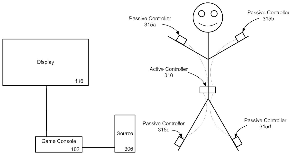
Referring now toFIG. 3, a block diagram of one embodiment of the present invention can be seen. Here game console102is coupled to display116for display output of the video game in operation. Game console102is also coupled via a cable or other means to a source306. Source306generates a magnetic field in the same manner as did source106ofFIGS. 1-2. Each of active controller310and passive controllers315a,315b,315cand315ddetect the generated magnetic field. Passive controllers315a,315b,315cand315dcommunicate in a wired or wireless fashion, as depicted by dashed lines in the figure, their detected magnetic field information to active controller310. Active controller310calculates the three dimensional position and orientation of each of passive controllers315a,315b,315cand315d, as well as the three dimensional position and orientation of active controller310, using the detected magnetic field information from each. Active controller310wirelessly communicates the calculated position and orientation of each of passive controllers315a,315b,315cand315dand active controller310to game console102either directly or via source306. This continues as each of passive controllers315a,315b,315cand315dand active controller310is moved thus continuously informing game console102of the position and orientation of each of passive controllers315a,315b,315cand315dand active controller310.
Referring now toFIG. 4, a block diagram of subcomponents of source306, active controller310and passive controller315(representative of any of passive controller315a,315b,315cand315d) can be seen. Source306includes source magnetic coils408that, as known in the art, generate a magnetic field. Active controller310includes sensing magnetic coils412athat, as known in the art, sense the generated magnetic field. Active controller310also includes a processing unit413which phase corrects the sensed magnetic field information as explained elsewhere herein. Processing unit413takes the phase corrected sensed magnetic field information and calculates, as known in the art, the three dimensional position and orientation of active controller310. Active controller310also includes a wireless transmitter414which transmits the calculated position and orientation of active controller110to a wireless receiver418of source306.
Passive controller315includes sensing magnetic coils412bthat, as is known in the art, sense the magnetic field generated by source magnetic coils408. Passive controller315transmits the sensed magnetic field information from sensing magnetic coils412bin a wired or wireless fashion, as depicted by a dashed line in the figure, to active controller310. Processing unit413of active controller310phase corrects the sensed magnetic field information from sensing magnetic coils412bof passive controller315and using that phase corrected information calculates, as known in the art, the three dimensional position and orientation of passive controller315. Wireless transmitter414of active controller310transmits the calculated position and orientation of passive controller315to wireless receiver418of source306.
This continues as passive controller315and active controller310are each moved thus continuously informing game console102of the position and orientation of each of passive controller315and active controller310.
In a preferred embodiment and using known techniques, source magnetic coils408are three orthogonal coils. Also in a preferred embodiment and using known techniques, sensing magnetic coils412aand412bare each three orthogonal coils. In various embodiments not shown in the figures, each of active controller310and passive controller315typically also includes various additional known componentry in operation with sensing magnetic coils412aand sensing magnetic coils412b. For example, pre-amplifiers, amplifiers, and analog-to-digital converters (ADCS) will typically be included in each controller, whether active or passive, although in alternative embodiments some or all of such additional known componentry may only exist in active controller310. It is to be understood that any combination of sensing coils, pre-amplifiers, amplifiers and ADCs, including only the sensing coils themselves, is referred to herein as a magnetic sensor.
As is known, processing sensed magnetic field information to calculate position and orientation of a controller typically involves intermediate steps in addition to phase correction as discussed elsewhere herein. For example, as described in incorporated by reference U.S. Pat. No. 4,737,794 (see, e.g., column 4 et seq.), sensed magnetic field information can first be turned into a signal matrix from which the position and orientation is calculated. As described, creating a signal matrix is a more involved set of operations than is calculating the position and orientation from the signal matrix which uses inherently simple algorithms. Stated differently, significantly more processing is required to create a signal matrix than to calculate position and orientation from the signal matrix. An alternative embodiment not shown capitalizes on this uneven division of labor. In this alternative embodiment the processing unit413still handles the bulk of the processing by creating a signal matrix from the phase corrected sensed magnetic field information but does not calculate the position and orientation of a controller. In this alternative embodiment the wireless transmitter414of active controller310then transmits the signal matrix to wireless receiver418of source306. Source306or game console102uses the received signal matrix to calculate the position and orientation of the controller, a relatively simple computational task.
In a preferred embodiment not shown, each of active controller310and passive controller315also includes various known input mechanisms and interactive means such as buttons, lights and switches for video game player interaction.
In a preferred embodiment processing unit413is a digital signal processor (DSP) running software and/or firmware to perform the operations described herein but in alternative embodiments is an application specific integrated circuit (ASIC) or a general purpose processor running software to perform the operations described herein. It is to be understood that any combination of hardware and software or instead hardware only may likewise be used.
It is to be understood that active controller310and passive controller315are housed in physically separate housings although they may incorporated into a single wearable garment or piece of apparel.
Referring now toFIG. 5, a flowchart of one embodiment of the present invention can be seen.
In step510, first magnetic sensor data is generated in a passive controller. This may be accomplished by sensing magnetic coils412bin passive controller315detecting a magnetic field generated by source magnetic coils408of source306.
In step515, the generated first magnetic sensor data is transmitted from the passive controller to an active controller. This may be accomplished by passive controller315transmitting the detected magnetic field information to active controller310.
In step520, the first magnetic sensor data is phase corrected in the active controller. Because the passive controller is not in wired communication with the source of the generated magnetic field, the sensed or detected first magnetic sensor data may not be in time or phase alignment with the generated magnetic field. Phase correcting the first magnetic sensor data brings the detected magnetic sensor data into alignment with the generated magnetic using techniques known in the art. Such known techniques include those described in U.S. patent application Ser. No. 12/017,392 (published as US 2008/0120061), U.S. patent application Ser. No. 12/157,725 (published as US 2009/0030646) and U.S. patent application Ser. No. 12,283,296 (published as US 2009/0076746), each of which is incorporated by reference herein. This phase correction may be accomplished by processing unit413of active controller310.
In step525, the three dimensional position and orientation of the passive controller is calculated in the active controller using techniques known in the art. This may be accomplished by processing unit413of active controller310.
In step530, the calculated position and orientation of the passive controller is transmitted from the active controller to a video game system. This may be accomplished by wireless transmitter414of active controller310transmitting to wireless receiver418of source306which in turn communicates with game console102.
In step535, second magnetic sensor data is generated in an active controller. This may be accomplished by sensing magnetic coils412ain active controller310detecting a magnetic field generated by source magnetic coils408of source306.
In step540, the second magnetic sensor data is phase corrected in the active controller. Because the active controller is not in wired communication with the source of the generated magnetic field, the sensed or detected second magnetic sensor data may not be in time or phase alignment with the generated magnetic field. Phase correcting the second magnetic sensor data brings the detected magnetic sensor data into alignment with the generated magnetic using techniques known in the art as explained elsewhere herein. This phase correction may be accomplished by processing unit413of active controller310.
In step545, the three dimensional position and orientation of the active controller is calculated in the active controller using techniques known in the art. This may be accomplished by processing unit413of active controller310.
In step550, the calculated position and orientation of the active controller is transmitted from the active controller to a video game system. This may be accomplished by wireless transmitter414of active controller310transmitting to wireless receiver418of source306which in turn communicates with game console102.
This process continues as the active controller and the passive controller are each individually moved thus continuously informing the video game system of the three dimensional position and orientation of each.
It is to be understood that the present invention is not limited to the particular sequence depicted inFIG. 5. For example, steps510through530may operate during the same period of time as, or overlap in time, steps535through550. As another example, phase correction steps520and540may be combined into a single phase correction operation before calculation steps525and545are performed. In another example, calculation steps525and545may be combined into a single calculation operation before steps530and550are performed. In yet another example, transmit steps530and550may be combined into a single transmit operation.
In an alternative embodiment not shown, in steps525and545, a signal matrix is created in the active controller which may be accomplished by processing unit413of active controller310. In this alternative embodiment, in steps530and550, the signal matrix is transmitted from the active controller to a video game system which may be accomplished by wireless transmitter414of active controller310transmitting to wireless receiver418of source306which in turn communicates with game console102. In this alternative embodiment, the received signal matrix is used to calculate the position and orientation of the controller either within source206or game console102.
It is to be understood that various alternative embodiments and sequences of operation are to be included in the scope of the present invention. For example, in one embodiment there may be only one passive controller and only one passive controller while in another embodiment there may be fewer than four passive controllers or more than four passive controllers. In another embodiment, there may be more than one active controller each of which interoperates with one or more passive controllers.
In a further embodiment, an active controller may calculate the position and orientation of more than one of an active and passive controller before transmitting the calculated position of each to a source. In a still further embodiment, the active controller may transmit the calculated position of more than one active or passive controller sequentially or at the same time.
In a still further embodiment, wireless receiver418may be coupled to or incorporated into game console102so that active controller310can transmit the calculated position of one or more controller directly to game console102rather than going through source306.
It is to be understood that game console102can also be utilized for some process other than operation of a video game. In such event, the apparatus and operations described herein are equally applicable to player or user interaction with such other process in essentially the same manner as described herein. As such, the present invention can be utilized with any computing system requiring user controller input.
The embodiments discussed herein are illustrative of the present invention. As these embodiments of the present invention are described with reference to illustrations, various modifications or adaptations of the methods and or specific structures described may become apparent to those skilled in the art. All such modifications, adaptations, or variations that rely upon the teachings of the present invention, and through which these teachings have advanced the art, are considered to be within the spirit and scope of the present invention. Hence, the description and the drawing should not be considered in a limiting sense, as it is understood that the present invention is in no way limited to only the embodiments illustrated.
Claims
- A video game controller system comprising: a passive controller including a first magnetic sensor having a first plurality of sensor coils for sensing a magnetic field to generate first magnetic sensor data;and an active controller in a physically separate housing from the passive controller, the active controller including: a second magnetic sensor having a second plurality of sensor coils for sensing the magnetic field to generate second magnetic sensor data;a wired receiver operative to receive the first magnetic sensor data from the passive controller;a processing unit operative to phase correct the first magnetic sensor data and calculate a position and orientation of the passive controller using the phase corrected first magnetic sensor data;the processing unit further operative to phase correct the second magnetic sensor data and calculate a position and orientation of the active controller using the phase corrected second magnetic sensor data;and a wireless transmitter operative to transmit to a video game system the calculated position and orientation of the active controller and the calculated position and orientation of the passive controller.
- The video game controller system of claim 1 wherein the processing unit is a DSP.
- The video game controller system of claim 1 further comprising a source including;a first plurality of source magnetic coils;and a wireless receiver for receiving from the active controller wireless transmitter the calculated position and orientation of the active controller and the calculated position and orientation of the passive controller for communication to the video game system.
- The video game controller system of claim 1 wherein the active controller is configured to be placed on or attached to the torso of a game player.
- The video game controller system of claim 1 wherein the passive controller is configured to be placed on or attached to the limb of a game player.
- The video game player system of claim 1 wherein the passive controller is configured to be placed on or attached to the head of a game player.
- A video game controller method comprising: generating first magnetic sensor data by sensing a magnetic field using a first controller including a first magnetic sensor having a first plurality of sensor coils;transmitting the first magnetic sensor data via a wired connection from the first controller to a second controller;phase correcting in a processing unit of the second controller the first magnetic sensor data;calculating in the second controller a position and orientation of the first controller using the phase corrected first magnetic sensor data;wirelessly transmitting from the second controller to a video game system the calculated position and orientation of the first controller;generating second magnetic sensor data by sensing the magnetic field using the second controller including a second magnetic sensor having a second plurality of sensor coils;phase correcting in the processing unit of the second controller the second magnetic sensor data;calculating in the second controller a position and orientation of the second device using the phase corrected second magnetic sensor data;and wirelessly transmitting from the second controller to the video game system the calculated position and orientation of the second controller.
- The video game controller method of claim 7 wherein the phase correcting is done by a DSP.
- The video game controller method of claim 7 further comprising generating the magnetic field using a source including a first plurality of source magnetic coils.
- The video game controller method of claim 9 wherein wirelessly transmitting from the second controller to the video game system is by the source receiving the wireless transmission and communicating the wireless transmission to the video game system in a wired transmission.
- The video game controller method of claim 7 wherein the method is repeated as the first controller and the second controller each continue to be separately moved.
- A video game controller system comprising: a passive controller including a first magnetic sensor having a first plurality of sensor coils for sensing a magnetic field to generate first magnetic sensor data;and an active controller in a physically separate housing from the passive controller, the active controller including: a second magnetic sensor having a second plurality of sensor coils for sensing the magnetic field to generate second magnetic sensor data;a wired receiver operative to receive the first magnetic sensor data from the passive controller;a processing unit operative to phase correct the first magnetic sensor data and create a first signal matrix using the phase corrected first magnetic sensor data;the processing unit further operative to phase correct the second magnetic sensor data and create a second signal matrix using the phase corrected second magnetic sensor data;and a wireless transmitter operative to transmit to a video game system the first signal matrix and the second signal matrix.
- The video game controller system of claim 12 wherein the processing unit is a DSP.
- The video game controller system of claim 12 further comprising a source including;a first plurality of source magnetic coils;a wireless receiver for receiving from the active controller wireless transmitter the first signal matrix and the second signal matrix;and a source processing unit operative to calculate the position and orientation of the active controller from the second signal matrix and calculate the position and orientation of the passive controller from the first signal matrix.
Disclaimer: Data collected from the USPTO and may be malformed, incomplete, and/or otherwise inaccurate.