U.S. Pat. No. 8,613,669
GAME CONTROLLER WITH DISPLAY AND METHODS THEREFOR
AssigneeActivision Publishing, Inc.
Issue DateApril 30, 2004
Illustrative Figure
Abstract
A game controller having a video display and messaging capability is provided. Such a system is especially useful for video games with multiple players and also for communicating with non-players. In one embodiment, a game controller useful is coupled to a game console which is coupled to a wide area network. The game console is used by a person playing a game on the game console using the game controller. The game controller includes a video display capable of displaying a message sent from a second person over the wide area network. These messages can include textual, video and/or audio data. Messages can be sent from the game controller to the game console, and received from the game console to the game controller via a USB port. The video display can also be used to display game data from the game console. In some embodiment, the game controller includes a keypad for inputting a textual message for the second person. Game controller can also include a camera and/or a microphone for inputting video and/or audio data to be included in a message for the second person. Game controller can also include audible alerts via a speaker or mechanical alerts via an alerter, alerting the person about incoming messages.
Description
DETAILED DESCRIPTION OF THE PREFERRED EMBODIMENTS The present invention will now be described in detail with reference to a few preferred embodiments thereof as illustrated in the accompanying drawings. In the following description, numerous specific details are set forth in order to provide a thorough understanding of the present invention. It will be apparent, however, to one skilled in the art, that the present invention may be practiced without some or all of these specific details. In other instances, well known process steps and/or structures have not been described in detail in order to not unnecessarily obscure the present invention. The features and advantages of the present invention may be better understood with reference to the drawings and discussions that follow. To facilitate discussion,FIGS. 1,2,3A,3B,4,5,6and7include block diagrams and flow diagrams which illustrate the operation of one embodiment of a video game controller and a game console coupled to a network. As shown inFIG. 1, a plurality of game consoles121,122. . .129is coupled to a suitable network110, e.g. a wide area network (WAN) such as the internet. WAN can be implemented using a wide range and combinations of wired and wireless technologies and protocols known to one skilled in the art, including Wi-Fi, Ethernet, Voice over IP (VoIP), ATM, and TCP/IP. In addition, the present invention is also useful in association with a local area network (LAN). Each game console is coupled to at least one game controller. For example, game console121is coupled to at least one game controller131. Telephone141is coupled to WAN110via local telephone company (Telco)140, computer151is coupled to WAN110via network interface150, and mobile (cellular) telephone161is coupled to internet110via cellular provider160. In some embodiments, game consoles121,122. . .129are each coupled to a video monitor or television (not shown). In accordance with the present invention, a first player operating any one ...
DETAILED DESCRIPTION OF THE PREFERRED EMBODIMENTS
The present invention will now be described in detail with reference to a few preferred embodiments thereof as illustrated in the accompanying drawings. In the following description, numerous specific details are set forth in order to provide a thorough understanding of the present invention. It will be apparent, however, to one skilled in the art, that the present invention may be practiced without some or all of these specific details. In other instances, well known process steps and/or structures have not been described in detail in order to not unnecessarily obscure the present invention. The features and advantages of the present invention may be better understood with reference to the drawings and discussions that follow.
To facilitate discussion,FIGS. 1,2,3A,3B,4,5,6and7include block diagrams and flow diagrams which illustrate the operation of one embodiment of a video game controller and a game console coupled to a network.
As shown inFIG. 1, a plurality of game consoles121,122. . .129is coupled to a suitable network110, e.g. a wide area network (WAN) such as the internet. WAN can be implemented using a wide range and combinations of wired and wireless technologies and protocols known to one skilled in the art, including Wi-Fi, Ethernet, Voice over IP (VoIP), ATM, and TCP/IP. In addition, the present invention is also useful in association with a local area network (LAN).
Each game console is coupled to at least one game controller. For example, game console121is coupled to at least one game controller131. Telephone141is coupled to WAN110via local telephone company (Telco)140, computer151is coupled to WAN110via network interface150, and mobile (cellular) telephone161is coupled to internet110via cellular provider160. In some embodiments, game consoles121,122. . .129are each coupled to a video monitor or television (not shown).
In accordance with the present invention, a first player operating any one of game controllers131,132. . .139can communicate with at least a second player operating another one of game controllers131,132. . .139, or computer151, or communicate with a non-player using telephone141, computer151or mobile telephone161.
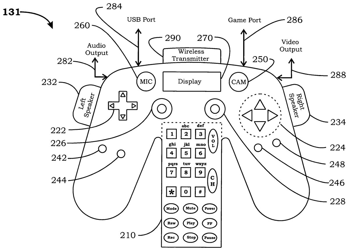
FIG. 2illustrates one embodiment of controller131. Note that the following discussion of exemplary controller131and console121also applied to controller132. . .139and consoles122. . .129. Controller131includes keypad210, game directional controls222,224, joysticks226,228, speakers232,234, game control buttons242,244,246,248, video camera250, microphone260, video display270, audio output282, game console USB port284, game console controller port286, video output288, and wireless transmitter290.
In some embodiments, keypad210of controller131can be used to control console121and/or additional electronic devices via either wireless transmitter290or a wired connection (not shown). Wireless transmitter290can be implemented using a wide range of wireless transmission technologies and protocols including radio-frequency (RF) or infrared red (IR), Ethernet, WiFi, and BlueTooth.
Cycling the “mode” key of keypad210enables the player to selectively control console121, a television/monitor, one or more electronic devices such as a video tape recorder (VCR), a digital video recorder (DVR), and a CD/DVD player or recorder. Accordingly, “Mode” key may cycle between choices from a menu which include one or more of “Console”, “TV”, “VCR”, “DVD”, “Messaging” and “Phone”.
In “Console” mode, controller131can be used to play a video game or watch a movie on console121. Keypad210can be used to send messages while playing the video game or movie. The “VOL” key can be used as a cursor, while the “CH” key can be used as an “Enter” key to end of a message. Video and/or audio can be controlled by using the “Mute” key on keypad210. For example, when “Console” mode is selected using the “Mode” key, cycling the “Mute” key will enable player to select from choices which include “Enable Video & Audio”, “Enable Video Only”, “Enable Audio Only”, and “Mute Video & Audio”.
As discussed above, in some embodiments, controller131also has a “messaging” mode and/or “phone” mode where keypad210can be used as in a manner similar to a telephone key pad for placing voice calls, e.g. VoIP, and or for exchanging textual messages over the internet, e.g., email or short message service (SMS).
Controller131also includes game directional controls222,224, joysticks226,228and game control buttons242,244,246,248for controlling the game playing on console121. Other input/output devices are also possible, e.g. steering wheel(s), gear selector(s), control level(s), trigger(s) and any other control devices, such as those found on cars, airplanes or boats and weapons.
Left and right speakers232,234are used to output game audio from console121and/or messages/alerts from the second player or non-player. Speakers232,234can be mounted on the surface of controller131, or mounted on adjustable posts attached to controller131. Speakers232,234can be also detached from controller131and coupled to controller131via a wired or wireless connection.
Microphone260can be monaural or stereo. Microphone260can be can be mounted on the surface of controller131, or mounted on an adjustable post attached to controller131. Microphone260can be detached from controller131and coupled to controller131via a wired or wireless connection. Microphone260can also be mechanically attached to a headset with earphones. Microphone260can be used to send audio messages to other players or non-players via console121.
Camera250can be implemented using monochrome, color, infrared red or any other suitable technology. Camera250can be mounted on the surface of controller131, or mounted on an adjustable post attached to controller131. Alternatively, camera250can be detached from controller131and coupled to controller131via a wired or wireless connection. Images from camera250can be sent to other players or non-players as video messages via console121.
Video display270can be based on a LCD, TFT, plasma, LED or any other suitable display technology. Video display270can be mounted flush on the surface of controller131. Video display270can also be adjustably mounted to controller131, such as in a flip-up configuration so that display270can be adjusted to suit the player, and display270can be in a closed protected position when not in use. In some embodiments, video display270is a touch screen display and can also include the functionality of keypad210.
Audio output282can drive either external earphones or external speakers. Video output288of controller131can drive two-dimensional/three-dimensional glasses or an external video monitor. Game console USB port284can be used for sending messages to other players and non-player via console121, while game console controller port286can be used for sending game command signals to console121.
Other modifications and combinations are also possible. For example, video images can be displayed using a video projector instead of video display270. It is also possible for a player can wear a headgear (not shown) which includes 2D/3D glasses, earphones and a microphone. The headgear can be coupled to controller131via a wired or wireless connection.
FIGS. 3A and 3Bare flow diagrams illustrating the operation of one embodiment of game controller131. Referring first toFIG. 3A, upon a Power On Reset (step314), controller131senses if Send_Packet_Flag is set (step322). Send_Packet_Flag is used by controller131to determine if a message or game command needs to be sent from controller131to console121.
If Send_Packet_Flag is not set, controller131reads keypad210(step324), and also reads game directional controls222,224, joysticks226,228, or game control buttons242,244,246,248(step326). In step328, if no packet from game console121detected, then controller131proceeds to step362.
If a packet has arrived from game console121(step328), and the packet includes display data (step332), then the textual message and/or video data is displayed (step334) on display270, and controller131proceeds to step362. Display message/data can be from one or more sources, including textual messages from other players or non-players, player/non-player directory information such as IP addresses, and/or game data from console121, for example, graphical dashboard data from a speedometer, an accelerometer, a tachometer, a gear shift display, an altimeter, a fuel gauge, an oil gauge, a depth gauge, and/or a radar scope, and any other displays found in an airplane, boat, or vehicle. In some embodiments, display270can also be configured to display the video signal normally sent by console121to a television.
Conversely, if a packet has arrived from game console121(step328), and the packet includes audio data (steps332and336), then the audio data is outputted on speakers232,234(step339), and controller131proceeds to step362. Audio message/data can be from one or more sources, including audio messages from other players or non-players, and/or game data from console121, for example, audio effects data from an engine, a weapon, and/or an incoming projectile.
In step338, if the packet from console121is neither a textual, a video nor an audio packet (steps328,332,336), then the packet may be a “motion” packet such as a “tactile feedback force” packet, and controller131responses accordingly, for example by vibrating an alerter (not shown) of controller131. Other uses of “motion” packets include alerts to the player that there is an incoming message. The “motion” packet can include enough information to identify the sender of the message, for example, two long buzzes followed by one short buzzes can be the identifier for a spouse. The “motion” packet can also include an embedded coded message as well.
In step322, if Send_Packet_Flag is set, then the player message or game command is packetized (step344). If the packet includes a message for another player or non-player (step346), then the packet is routed to USB port284to be sent to game console121(step348). Messages can include textual, audio and/or video data. Conversely, if the packet includes a game command for console121, then the packet is routed to game console121via controller port286(step349). Upon sending the command or message packet, controller131resets the Send_Packet_Flag (step352) and proceeds to step316.
Referring now toFIG. 3B, if controller131is in “Enable Video” and/or “Enable Audio” mode (step372), then the video data from camera250and/or audio data from microphone260is read and the Send_Packet_Flag is set (step374).
Controller131also senses if any key of keypad210has been pressed (step376), and if so a Keypad Packet is sent to the appropriate device via wireless transmitter290(step378). An example of a Keypad Packet would be an “Increase Volume” key for a television coupled to game console121.
In step382, if the “Power” key of keypad210is pressed while controller131is in “Full Power” mode, then controller131goes into a “Hibernation” mode to conserve power (step392). The “hibernation” mode is especially useful in embodiments where controller131is wireless and is not powered by console121, i.e. battery powered. Controller131remains in hibernation until “Power” key of keypad210is pressed, and controller131stands by for a transition into a “Full Power” mode (step394). Controller121then waits for a “Resume” command from game console121before transitioning back to the “Full Power” mode and returning to normal operation (396).
In normal “Full Power” operation, when controller131senses that any of joystick game directional controls222,224, joysticks226,228, or game control buttons242,244,246,248has been pressed (384), controller131sets the Send_Packet_Flag (step386), and proceeds to step316. Controller131then repeats flow diagram330aand330bofFIGS. 3A and 3B, starting at step316.
FIGS. 4,5and6are exemplary flow diagrams illustrating the operation of game console121which is coupled to game controller131as shown inFIG. 1.FIG. 7illustrates one embodiment of console121with multiple software program layers. Referring first toFIGS. 4 and 7, which illustrates an exemplary boot sequence for console121, in step414, console121executes a Power On Reset and loads a console basic input/output system (BIOS)710which functions as an operating system for console121.
Since console game program730for controller121is typically stored either in a game cartridge or in a CD/DVD ROM, console messenger720of the present invention can also be stored in a similar memory format and inserted into console121(step416). Other methods for storing and downloading console messenger720are also possible. For example, console messenger720can also be initially stored in a remote location and upon request downloaded onto console121via WAN110. Console messenger720can also be stored in firmware on controller121and downloaded onto console121via USB port284. Messenger720can also be in the firmware of console121and hence there will be no need for loading messenger720from a source external to console121.
In this embodiment, console messenger720is implemented as middleware and is loaded after the console BIOS but before game program730. It is also possible to incorporate the present invention into an existing game program by integrating the console messenger720and game program730into a game program with built-in messaging capability and loaded into console121using a single game cartridge or DVD ROM.
Block420illustrates an exemplary auto rebooter and a TCP/IP sniffer load sequence for loading console messenger720. In step422, a TCP/IP stack and a Voice over IP (VoIP) stack of console messenger720are initialized. Console messenger720includes a USB Host Controller, responsible for managing the USB Port communications between controller131and console121, which is also initialized (step424). Console messenger720also initializes a Network Controller, responsible for managing communications with other players and/or non-players over the WAN, and reads the game cartridge address list (step426). A directory of addressees which include information such as names and their respective IP addresses can be stored locally by console121and/or at a remote location coupled to WAN110.
In step428, console messenger720logs player onto the WAN110so that connections can be made with other player(s) and/or non-player(s), and messenger720also hooks onto Reset Command Interrupt Request (IRQ) of BIOS710. When messenger720is completely loaded into the memory of console121, messenger DVD ROM is ejected by console121(step432). Upon ejection of messenger DVD ROM, game program730on a game DVD ROM is loaded into the memory of console121, and messenger720proceeds to step512ofFIG. 5.
In step514ofFIG. 5, messenger720resets the appropriate IRQs of BIOS710which have been set by console game program730. Console121then verifies that messenger720has been properly loaded by computing a checksum of console memory space occupied by messenger720(step516). In step522and524, if the computed memory sum does not match the checksum, console121waits for a Power On Reset command from controller131before returning to step414.
When console program layers, BIOS710, messenger720and console game program730, are successfully loaded in the memory of console212, messenger720is executes its code in the processor of console212(step532), and is subject to interrupts from console game program730(box534).
When an audio or video packet arrived from WAN110(steps542,546), messenger720extracts audio/video data from the packet, encodes the data into a suitable USB format, and then sends the audio/video message on a USB ISOCH Out Pipe to controller131(steps564and582). Extraction of audio/video data may include, for example, decoding a pulse-code-modulated (PCM) audio packet.
Conversely, as shown in steps542and546, if a textual message arrived from WAN110, then messenger720decodes the TCP/IP packet, extracts and sends the textual message on a USB Bulk Pipe to controller131(steps552,554and582). Upon sending the video/audio/textual message to controller131, messenger720returns to step532. In some embodiments, console121may also generate game-related audio and/or video data which can be sent to controller131using, for example, the USB ISOCH Out Pipe.
FIG. 6illustrates the processing of a USB packet sent by controller131to console121. As the USB Host, messenger720executing on console121is responsible for managing USB packets to and from controller131.
In steps614,616,632,634and636, when a USB Keypad Key packet arrives from controller131, messenger720processes the Scan Codes, and buffers the keystrokes for the textual message until the textual message is completed. A TCP/IP wrapper is then added to form a TCP/IP textual message packet (step638).
If the USB packet from controller131is not a Keypad Key packet, and is an Audio message (step624), a VoIP wrapper is added to form a VoIP packet (step626), while a TCP/IP wrapper is added to a Video message to form a TCP/IP Video packet (step638). Depending on the protocol(s) used, messenger720may, for example, encode the PCM Audio data before adding the VoIP wrapper. Other video and audio WAN transmission/compression/encryption protocols known to one skilled in the art are possible, including H.323 (IP Communications), H.263 (Video), H.711 (Audio), and H.723 (Audio).
In steps642and644, when message packet is properly formatted, messenger720retrieves the addressee's (another player or non-player) IP address stored in console121and sends the textual, video or audio IP packet out to WAN110. Upon sending the message out to the WAN110, messenger720returns step532.
Many modifications to controller131and game console121are also possible. For example, instead of using two wired connections (USB port284and game port286) and a wireless connection (IR transmitter290) for messages and game commands, controller131and console121can also use a single wired connection or a single wireless connection.
Although the above exemplary description uses protocols such as PCM, TCP/IP, VoIP, USB, and ISOCH and Bulk pipes, it is possible to use other protocols known to one skilled in the art. In addition, the functionality of controller131and messenger720of console121can be in software, firmware, hardware or combinations thereof.
Advantages of the present invention include the ability to communicate with other players and non-players over WAN110, the ability to alert the player of incoming messages, the ability to control other electronic devices, and the ability to exchange messages with other non-game-centric devices such as telephones, mobile phones, and computers.
While this invention has been described in terms of several preferred embodiments, there are alterations, modifications, permutations, and substitute equivalents, which fall within the scope of this invention. It should also be noted that there are many alternative ways of implementing the methods and apparatuses of the present invention. It is therefore intended that the following appended claims be interpreted as including all such alterations, modifications, permutations, and substitute equivalents as fall within the true spirit and scope of the present invention.
Claims
- A method for communicating with a person playing a video game comprising: during game play on a game console, receiving a textual message at a video game controller wirelessly connected to the game console, the textual message being from another person over a wide area network and is sent from a second video game controller coupled to the wide area network via a second game console, the game console coupled to a television, wherein the textual message is intended for the person playing the video game using the video game controller;and displaying the textual message on a video display of the video game controller, the video game controller including controls for controlling game play on the game console and a keypad configured for placing voice calls and for sending textual messages over the wide area network.
- The method of claim 1 , wherein the wide area network is an internet.
- The method of claim 2 , wherein the message is wirelessly received from the game console.
- The method of claim 1 further comprising: sending a reply to the other person over the wide area network;and displaying the reply for the other person.
- The method of claim 4 , wherein the other person is using the second video game controller wirelessly connected to the second game console.
- A game controller comprising: at least controls for controlling game play on a game console;a wireless connection to a wide area network;a wireless connection to a game console coupled to a television, wherein the game console is configured for use by a first person playing a game using the game controller;a keypad configured for placing voice calls and for sending textual messages over the wide area network;a display of the game controller configured to display a textual message for the first person playing the game, the textual message being from a second person over the wide area network and is sent from a second game controller coupled to the wide area network via a second game console.
- The game controller of claim 6 , wherein the wide area network is an internet.
- The game controller of claim 7 , wherein the message is wirelessly received from the game console.
- The game controller of claim 7 , wherein the game controller is further configured to send a reply to the second person over the wide area network.
- The game controller of claim 9 , further comprising the keypad configured for inputting the reply to be sent to the second person.
- The game controller of claim 10 , wherein the keypad is configured to control one of a television, an analog video recorder, and a digital video recorder.
- The game controller of claim 10 , wherein the keypad is configured to control the game console to play a movie.
- The game controller of claim 9 , wherein the second person is using the second game controller wirelessly connected to the second game console.
- The game controller of claim 6 , further comprising a camera configured for inputting video data for a reply to be sent to the second person over the wide area network.
- The game controller of claim 6 , further comprising a microphone configured for inputting audio data for a reply to be sent to the second person over the wide area network.
- The game controller of claim 6 , further comprising at least one speaker configured for receiving audio data from the second person.
- The game controller of claim 6 , further comprising an alerter configured for receiving an alert from the second person.
- The game controller of claim 17 wherein the alerter is a mechanical device.
Disclaimer: Data collected from the USPTO and may be malformed, incomplete, and/or otherwise inaccurate.