U.S. Pat. No. 8,608,576
LENS ACCESSORY FOR VIDEO GAME SENSOR DEVICE
AssigneeNyko Technologies, Inc.
Issue DateFebruary 23, 2012
Illustrative Figure
Abstract
A lens accessory for a video game sensor device and a method of adjusting a sensing distance of a video game sensor device. A lens accessory for a video game sensor device includes a first lens configured to cover an infrared light emitter of the video game sensor device, a second lens configured to cover an infrared light receiver of the video game sensor device, and a body portion coupling the first lens and the second lens together, the body portion being removably attachable to the video game sensor device, and the first lens and the second lens having a magnification for adjusting a sensing distance of the video game sensor device.
Description
DETAILED DESCRIPTION In the following detailed description, certain exemplary embodiments of the present invention are shown and described, by way of illustration. As those skilled in the art would recognize, the described exemplary embodiments may be modified in various ways without departing from the spirit and scope of the present invention. Accordingly, the drawings and description are to be regarded as illustrative in nature, rather than restrictive. Further, terms such as “upper,” “lower,” “front,” “back,” “top,” “bottom,” “upward,” and “downward” are used herein for the purpose of more clearly describing the location and/or orientation of components or features relative to others, as shown in the drawings, for example. However, the use of such terms is not intended or to be regarded as limiting the use of the invention to any particular position or orientation. With reference toFIGS. 1-4, a video game sensor device10according to one exemplary embodiment of the present invention includes a lens apparatus50. In one embodiment, the lens apparatus50is movable between an adjusting position, as shown inFIGS. 1-4, in which at least one lens of the lens apparatus50covers at least one of an infrared light emitter42, an infrared light receiver44, and a camera45of the video game sensor device10, and a non-adjusting position (seeFIGS. 5-8) in which the lens apparatus50does not cover the infrared light emitter42, the infrared light receiver44, and the camera45. With reference toFIGS. 5-8, the video game sensor device10includes a casing20which houses the infrared light emitter42, the infrared light receiver44, and the camera45. In one embodiment, the casing20has a generally rectangular or trapezoidal prismatic shape including a front side22, a top side24, a rear side26, and a bottom side28. The infrared light emitter42, the infrared light receiver44, and the camera45, in one embodiment, are facing the front side22, and the front side22may have one or more ...
DETAILED DESCRIPTION
In the following detailed description, certain exemplary embodiments of the present invention are shown and described, by way of illustration. As those skilled in the art would recognize, the described exemplary embodiments may be modified in various ways without departing from the spirit and scope of the present invention. Accordingly, the drawings and description are to be regarded as illustrative in nature, rather than restrictive. Further, terms such as “upper,” “lower,” “front,” “back,” “top,” “bottom,” “upward,” and “downward” are used herein for the purpose of more clearly describing the location and/or orientation of components or features relative to others, as shown in the drawings, for example. However, the use of such terms is not intended or to be regarded as limiting the use of the invention to any particular position or orientation.
With reference toFIGS. 1-4, a video game sensor device10according to one exemplary embodiment of the present invention includes a lens apparatus50. In one embodiment, the lens apparatus50is movable between an adjusting position, as shown inFIGS. 1-4, in which at least one lens of the lens apparatus50covers at least one of an infrared light emitter42, an infrared light receiver44, and a camera45of the video game sensor device10, and a non-adjusting position (seeFIGS. 5-8) in which the lens apparatus50does not cover the infrared light emitter42, the infrared light receiver44, and the camera45.
With reference toFIGS. 5-8, the video game sensor device10includes a casing20which houses the infrared light emitter42, the infrared light receiver44, and the camera45. In one embodiment, the casing20has a generally rectangular or trapezoidal prismatic shape including a front side22, a top side24, a rear side26, and a bottom side28. The infrared light emitter42, the infrared light receiver44, and the camera45, in one embodiment, are facing the front side22, and the front side22may have one or more openings exposing the infrared light emitter42, the infrared light receiver44, and the camera45. Further, in one embodiment, the casing20of the video game sensor device10includes a support post30coupled to the bottom side28for supporting the video game sensor device10on a support base, for example.
With further reference toFIGS. 1-4, the lens apparatus50includes a body portion including a front side52, a top side54, a rear side56, and a bottom side58that are spaced apart from one another and configured similarly to the respective front side22, top side24, rear side26, and bottom side28of the casing20and are mounted thereto. The body portion may be made of a thermoplastic material (e.g., SABIC PC/ABS C6200) or any other suitable material. The lens apparatus50further includes a first lens62, a second lens64, and, in one embodiment, a third lens65coupled to the front side52. In one embodiment, the first lens62, the second lens64, and the third lens65are configured to cover the infrared light emitter42, the infrared light receiver44, and the camera45, respectively, for adjusting a sensing distance of the video game sensor device10. Each of the first lens62, the second lens64, and the third lens65has a magnification, and, in one embodiment, the magnification of each is the same. The magnification may be selected depending on the amount by which the sensing distance of the video game sensor device10is desired to be adjusted. For example, where it is desired that the sensing distance of the video game sensor device10be adjusted to be less (e.g., for use in a small room), the first lens62, the second lens64, and the third lens65may have a magnification of less than 1×. For example, in one embodiment, the first lens62, the second lens64, and the third lens65may have a magnification of about 0.5× to about 0.7×. In one embodiment, the first lens62, the second lens64, and the third lens65have a magnification of about 0.6×. However, the present invention is not limited thereto and, in other embodiments, the first lens62, the second lens64, and the third lens65may have any other suitable magnification. Further, in another embodiment, if it is desired that the sensing distance of the video game sensor device10be adjusted to be greater, the first lens62, the second lens64, and the third lens65may have a magnification of greater than 1×. Further, in one embodiment, the first lens62, the second lens64, and the third lens65may have a magnification that is adjustable. Further, in one embodiment, the first lens62, the second lens64, and the third lens65may be coated with a coating material that is configured to block non-infrared light.
The lens apparatus50is coupled (e.g., removably attached) to a video game sensor device and, in one embodiment, includes a clip portion70. The clip portion70may be configured as a pair of opposing hooks72having an opening74therebetween receiving the support post30therein. The hooks72may be elastically deformable for receiving the support post therebetween and for clamping around the support post30for attachment of the lens apparatus50to the support post30. However, embodiments of the present invention are not limited to the clip portion70described above and shown in the drawings. Rather, in other embodiments, the lens apparatus50may include any other suitable clip portion or other attachment device or method, or combination thereof, for removably or permanently attaching the lens apparatus50to the casing20. Further, in one embodiment, the casing20and the lens apparatus50may be integrally manufactured as a unit.
While, in one embodiment, the casing20and the lens apparatus50each have four sides forming a generally rectangular cross-sectional shaped body, the present invention is not limited thereto. That is, in other embodiments, one or both of the casing20or the lens apparatus50may have any suitable shape or number of sides for coupling to one another. Further, in one embodiment the casing20, the infrared light emitter42, the infrared light receiver44, and the camera45may be configured the same or similarly to the KINECT, as depicted inFIGS. 1-8, but in other embodiments, may have configurations different from that of the KINECT.
In one embodiment, as shown inFIGS. 4 and 8, for example, the front side52is connected to the top side54, the top side54is rotatably connected to the rear side56via a hinge80, and the rear side56is connected to the bottom side58. In one embodiment, the top side54is rotatable together with the first lens62, the second lens64, and the third lens65relative to the rear side56and the casing20via the hinge80for moving the first lens62, the second lens64, and the third lens65between an adjusting position (seeFIGS. 1-4) in which the first lens62, the second lens64, and the third lens65cover the infrared light emitter42, the infrared light receiver44, and the camera45, and a non-adjusting position (seeFIGS. 5-8) in which the first lens62, the second lens64, and the third lens65do not cover the infrared light emitter42, the infrared light receiver44, and the camera45. In other embodiments, the hinge80may be located between the front side52and the top side54or between the rear side56and the bottom side58. In another embodiment, more than one pair of sides may be rotatably connected. Further, in another embodiment, the hinge80may be absent, and the lens apparatus50may be configured for at least one of the first lens62, the second lens64, and the third lens65to cover at least one of the infrared light emitter42, the infrared light receiver44, and the camera45by any other device or method, such as the first lens62, the second lens64, and the third lens65being slidably movable relative to the infrared light emitter42, the infrared light receiver44, and the camera45.
With reference toFIG. 9, according to one embodiment, the first lens62and the second lens64of the lens apparatus50are oriented at an angle relative to each other such that respective center axes66and68of the first lens62and the second lens64cross each other at a convergence point CP. That is, both the first lens62and the second lens64aim at the convergence point CP. In one embodiment, the center axis66of the first lens62is oriented at an angle α with respect to an axis perpendicular to the front side22of the casing20and/or an axis perpendicular to the front side52of the lens apparatus50. Similarly, the center axis68of the second lens64is oriented at an angle β with respect to an axis perpendicular to the front side22of the casing20and/or an axis perpendicular to the front side52of the lens apparatus50. In one embodiment, the angles α and β are equal or substantially equal. However, embodiments of the present invention are not limited thereto, and in other embodiments, the angles α and β may be different. In one embodiment, the angles α and β may each be about 1.1 degrees. In one embodiment, respective edges of the first lens62(see, for example, edge162ashown inFIG. 19) and the second lens64which abut the front side22of the casing20are beveled in order to provide the angles α and β. Also, in one embodiment, the respective center axes66and68of the first lens62and the second lens64are substantially horizontal, such that the convergence point CP is at substantially a same height as the first lens62and the second lens64. Further, in one embodiment, the first lens62and the second lens64may be stationary, or fixed, relative to each other, and the angles α and β are constant. Alternatively, in another embodiment, the orientation of one or both of the first lens62and the second lens64may be moveable (i.e. the angles α and β are variable), such as for adjusting a distance from the lens accessory50to the convergence point CP. In another embodiment, the respective center axes66and68of the first lens62and the second lens64may not cross each other at a convergence point CP but, rather, each of the first lens62and the second lens64may be oriented parallel to an axis perpendicular to the front side22of the casing20and/or an axis perpendicular to the front side52of the lens apparatus50. That is, in one embodiment, each of the angles α and β is 0 degrees.
With reference toFIGS. 10 and 11, a lens accessory100according to an embodiment of the present invention is mountable, attachable, or otherwise useable with a video game sensor device for adjusting a sensing distance of the video game sensor device. The lens accessory100may be configured as lens goggles mountable on a video game sensor device, such as the KINECT or any other suitable video game sensor device. Furthermore, the lens accessory100, in one embodiment, as shown inFIGS. 10 and 11, has a same or substantially same configuration as that of the lens apparatus50described above and shown inFIGS. 1-9as a component of the video game sensor device10. However, embodiments of the present invention are not limited thereto, and in other embodiments, the lens accessory100may have any other suitable configuration for covering a video game sensor device and adjusting a sensing distance thereof.
In one embodiment, as shown inFIGS. 10 and 11, the lens accessory100has substantially the same configuration as the lens apparatus50described above. That is, the lens accessory100includes the body portion including the front side52, the top side54, the rear side56, and the bottom side58, and further includes the first lens62, the second lens64, and, in one embodiment, the third lens65coupled to the front side52. The body portion may be made of a thermoplastic material (e.g., SABIC PC/ABS C6200) or any other suitable material. The first lens62, the second lens64, and the third lens65are configured to cover an infrared light emitter, an infrared light receiver, and a camera, respectively, of a video game sensor device for adjusting a sensing distance of the video game sensor device. Also, as described above with respect to the lens apparatus50, each of the first lens62, the second lens64, and the third lens65of the lens accessory may have a magnification that is the same, and in one embodiment, for example, the first lens62, the second lens64, and the third lens65may have a magnification of about 0.5× to about 0.7×, such as a magnification of about 0.6×. However, in other embodiments, the magnification may be any other desired amount depending on a degree to which the user desires to adjust a sensing distance of a video game sensor device. In one embodiment, the first lens62, the second lens64, and the third lens65may have a magnification that is adjustable. Further, in one embodiment, the first lens62, the second lens64, and the third lens65may be coated with a coating material that is configured to block non-infrared light.
The lens accessory100is coupleable (e.g., removably attachable) to a video game sensor device and, in one embodiment, includes the clip portion70. As shown in further detail inFIG. 11, the clip portion70may be configured as a pair of opposing hooks72having an opening74therebetween for receiving a support post of a video game sensor device therein. The hooks72may be elastically deformable for receiving the support post therebetween and for clamping around the support post for attachment of the lens accessory100to the support post. However, embodiments of the present invention are not limited to the clip portion70described above and shown in the drawings. Rather, in other embodiments, the lens accessory100may include any other suitable clip portion or other attachment device or method, or combination thereof, for removably or permanently attaching the lens accessory100to a video game sensor device.
While in one embodiment the lens accessory100has four sides forming a generally rectangular cross-sectional shaped body, the present invention is not limited thereto. That is, in other embodiments, the lens accessory100may have any suitable shape or number of sides for coupling with any of various video game sensor devices, which may have configurations different from that of the KINECT, the general shape of which is depicted inFIGS. 1-9as the housing20of the video game sensor device10. Further, in one embodiment, as shown in the drawings, the front side52is connected to the top side54, the top side54is rotatably connected to the rear side56via the hinge80, and the rear side56is connected to the bottom side58. However, in other embodiments, the hinge80may be located between the front side52and the top side54or between the rear side56and the bottom side58. In another embodiment, more than one pair of sides may be rotatably connected. Further, in another embodiment, the hinge80may be absent, and the lens accessory100may be configured for at least one of the first lens62, the second lens64, and the third lens65to cover at least one of an infrared light emitter, an infrared light receiver, and a camera of a video game sensor device by any other device or method, such as the first lens62, the second lens64, and the third lens65being slidably movable relative to the infrared light emitter, the infrared light receiver, and the camera.
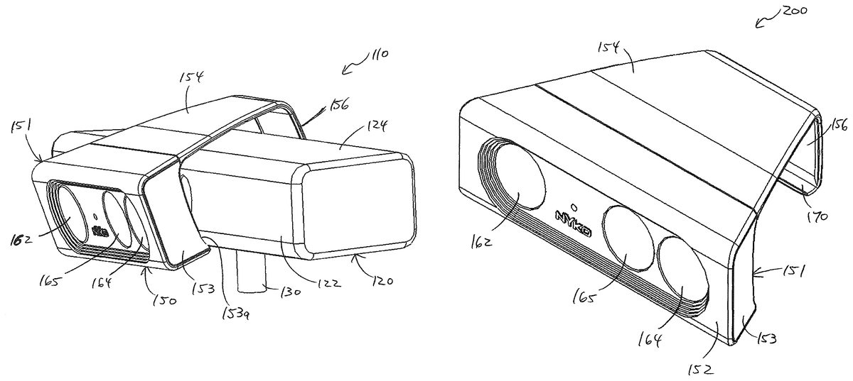
With reference toFIGS. 12-17, a video game sensor device110according to another exemplary embodiment of the present invention includes a lens apparatus150. In one embodiment, the lens apparatus150is movable or detachably coupleable to a casing120of the video game sensor device110between an adjusting position, as shown inFIG. 12, in which at least one lens of the lens apparatus150covers at least one of an infrared light emitter142, an infrared light receiver144, and a camera145of the video game sensor device110, and a non-adjusting position in which the lens apparatus150does not cover the infrared light emitter142, the infrared light receiver144, and the camera145, such as where the lens apparatus150is uncoupled from the casing120.FIG. 13shows the lens apparatus150partially uncoupled from the casing120. That is, inFIG. 13, a front portion of the lens apparatus150is coupled to the casing120, but a rear portion is detached, or unclipped, from the casing120.
With reference toFIGS. 12-17, the video game sensor device110includes a casing120which houses the infrared light emitter142, the infrared light receiver144, and the camera145. In one embodiment, the casing120has a generally rectangular or trapezoidal prismatic shape including a front side122, a top side124, a rear side126, and a bottom side128. The infrared light emitter142, the infrared light receiver144, and the camera145, in one embodiment, are facing the front side122, and the front side122has one or more openings exposing the infrared light emitter142, the infrared light receiver144, and the camera145. Further, in one embodiment, the casing120of the video game sensor device110includes a support post130coupled to the bottom side128for supporting the video game sensor device110on a support base, for example.
The lens apparatus150includes a body portion including a front side152, a top side154, a rear side156, and a bottom side158that are spaced apart from one another and configured similarly to the respective front side122, top side124, rear side126, and bottom side128of the casing120and are mounted thereto. The lens apparatus150further includes a first lens162, a second lens164, and, in one embodiment, a third lens165coupled to the front side152. In one embodiment, the first lens162, the second lens164, and the third lens165are configured to cover the infrared light emitter142, the infrared light receiver144, and the camera145, respectively, for adjusting a sensing distance of the video game sensor device110. Each of the first lens162, the second lens164, and the third lens165has a magnification, and, in one embodiment, the magnification of each is the same. The magnification may be selected depending on the amount by which the sensing distance of the video game sensor device110is desired to be adjusted. For example, where it is desired that the sensing distance of the video game sensor device110be adjusted to a shorter distance (e.g., for use in a small room), the first lens162, the second lens164, and the third lens165may have a magnification of less than 1×. For example, in one embodiment, the first lens162, the second lens164, and the third lens165may have a magnification of about 0.5× to about 0.7×. In one embodiment, the first lens162, the second lens164, and the third lens165have a magnification of about 0.6×. However, the present invention is not limited thereto and, in other embodiments, the first lens162, the second lens164, and the third lens165may have any other suitable magnification. Further, in another embodiment, if it is desired that the sensing distance of the video game sensor device110be adjusted to be a greater distance, the first lens162, the second lens164, and the third lens165may have a magnification of greater than 1×. Further, in one embodiment, the first lens162, the second lens164, and the third lens165may have a magnification that is adjustable. Further, in one embodiment, the first lens162, the second lens164, and the third lens165may be coated with a coating material that is configured to block non-infrared light.
The lens apparatus150is coupled (e.g., removably attached) to a video game sensor device and, in one embodiment, includes a clip portion170. The clip portion170, in one embodiment, may be configured as a concave rounded edge portion which is curved inward from an end of the rear side156for being attached or clipped to an intersecting region of the rear and bottom sides126and128of the casing120. The body portion of the lens apparatus150including the clip portion170may be elastically deformable for being clipped onto the casing120and, in one embodiment, for being held on the casing120by elastic force. That is, the body portion and/or the clip portion170may, for example, be made of a thermoplastic material (e.g., SABIC PC/ABS C6200) or another elastically deformable material. However, embodiments of the present invention are not limited to the clip portion170described above and shown in the drawings. Rather, in other embodiments, the lens apparatus150may include any other suitable clip portion or other attachment device or method, or combination thereof, for removably or permanently attaching the lens apparatus150to the casing120. Further, in one embodiment, the casing120and the lens apparatus150may be integrally manufactured as a unit. In another embodiment, one or more pairs of sides of the lens apparatus150may be rotatably connected to one another, similar to the lens apparatus50described above.
In one embodiment, the casing120and the lens apparatus150each have four sides forming a generally rectangular cross-sectional shaped body. However, the casing120of the video game sensor device110is not limited to the configuration shown inFIG. 14. In other embodiments, the casing120may have any suitable shape and number of sides, and the lens apparatus150may also have any other suitable shape for attachment to the casing120. Further, in one embodiment, the casing120, the infrared light emitter142, the infrared light receiver144, and the camera145may be configured the same or similarly to the KINECT, as depicted inFIG. 14, but in other embodiments, may have configurations different from that of the KINECT.
In one embodiment, as shown inFIGS. 15 and 16, for example, the bottom side158is connected to the front side, the front side152is connected to the top side154, the top side154is connected to the rear side156, and the rear side156is connected to the clip portion170. Further, with reference toFIG. 13, for example, the lens apparatus150may include a front housing portion151housing the first lens162, the second lens164, and the third lens165. In one embodiment, the front housing portion151includes the front side152, the bottom side158, a portion of the top side154, and a pair of side walls153at opposite sides of the front housing portion151. The side walls153may have a contoured edge153ahaving one or more curved portions corresponding to one or more curved portions of the casing120, such as curved intersecting portions between the front and top sides122,124and the front and bottom sides122,128. In one embodiment, the top side154includes a downwardly extending concave portion154ahaving curvature corresponding to that of a curved intersecting portion between the front and top sides122,124of the casing120. In one embodiment, the bottom side158includes an upwardly extending concave portion158ahaving curvature corresponding to that of a curved intersecting portion between the front and bottom sides122,128of the casing120.
In one embodiment, the second lens164is at least partially insertable in a cavity148adjacent the infrared light receiver144(seeFIGS. 15 and 17). Similarly, in one embodiment, with reference toFIG. 14, the first lens162is partially insertable in a cavity146adjacent the infrared light emitter142, and the third lens165is partially insertable in a cavity149adjacent the camera145.
In one embodiment, the lens apparatus150includes a biasing mechanism172, such as a compression spring. The biasing mechanism172pushes against a rib or ring164aof the second lens164(see, e.g.,FIG. 17) and thereby pushes the second lens164toward and into the cavity148of the casing120adjacent the infrared light receiver144and provides a retention force for holding the second lens164in the cavity148and against a surface in the cavity148. Further, the second lens164, in one embodiment, may include a stepped portion164bconfigured to abut a surface174of the front housing portion151when the second lens164is not inserted in and pushed against a surface in the cavity148. In one embodiment, the first lens162is biased toward the cavity146adjacent the infrared light emitter142, and the third lens165is biased toward the cavity149adjacent the camera145via a biasing mechanism in a similar manner as described above with respect to the second lens164. In other embodiments, the biasing mechanism172may include any other suitable biasing mechanism instead of or in addition to a compression spring.
With reference toFIGS. 18-20, a lens accessory200according to an exemplary embodiment of the present invention is mountable, attachable, or otherwise useable with a video game sensor device for adjusting a sensing distance of the video game sensor device. The lens accessory200may be configured as lens goggles mountable on a video game sensor device, such as the KINECT or any other suitable video game sensor device. Furthermore, the lens accessory200, in one embodiment, as shown inFIGS. 18-20, has a same or substantially same configuration as that of the lens apparatus150described above and shown inFIGS. 12-17as a component of the video game sensor device110. However, embodiments of the present invention are not limited thereto, and in other embodiments, the lens accessory200may have any other suitable configuration for covering a video game sensor device and adjusting a sensing distance thereof.
In one embodiment, as shown inFIGS. 18-20, the lens accessory200has substantially the same configuration as the lens apparatus150described above. That is, the lens accessory200includes the body portion including the front side152, the top side154, the rear side156, and the bottom side158, and further includes the first lens162, the second lens164, and, in one embodiment, the third lens165coupled to the front side152. The first lens162, the second lens164, and the third lens165are configured to cover an infrared light emitter, an infrared light receiver, and a camera, respectively, of a video game sensor device for adjusting a sensing distance of the video game sensor device. Also, as described above with respect to the lens apparatus150, each of the first lens162, the second lens164, and the third lens165of the lens accessory may have a magnification that is the same, and in one embodiment, for example, the magnification of each of the first lens162, the second lens164, and the third lens165may be about 0.5× to about 0.7×, such as a magnification of about 0.6×. However, in other embodiments, the magnification may be any other desired amount depending on a degree to which the user desires to adjust a sensing distance of a video game sensor device. In one embodiment, the first lens162, the second lens164, and the third lens165may have a magnification that is adjustable. Further, in one embodiment, the first lens162, the second lens164, and the third lens165may be coated with a coating material that is configured to block non-infrared light.
The lens accessory200is coupleable (e.g., removably attachable) to a video game sensor device and, in one embodiment, includes the clip portion170configured to clip onto the video game sensor device, as described above with respect to the lens apparatus150. Further, the lens accessory200, in one embodiment, is elastically deformable for fitting over and clamping around an outer casing of the video game sensor device. That is, the body portion and/or the clip portion170may, for example, be made of a thermoplastic material (e.g., SABIC PC/ABS C6200) or another elastically deformable material. However, embodiments of the present invention are not limited to the clip portion170described above and shown in the drawings. Rather, in other embodiments, the lens accessory200may include any other suitable clip portion or other attachment device or method, or combination thereof, for removably or permanently attaching the lens accessory200to a video game sensor device.
While, in one embodiment, the lens accessory200has four sides forming a generally rectangular cross-sectional shaped body, the present invention is not limited thereto. That is, in other embodiments, the lens accessory200may have any suitable shape or number of sides for coupling with any of various video game sensor devices, which may have configurations different from that of the KINECT, the general shape of which is depicted inFIG. 14as the casing120of the video game sensor device110. In one embodiment, as shown inFIGS. 18-20, the bottom side158is connected to the front side152, the front side152is connected to the top side154, the top side154is connected to the rear side156, and the rear side156is connected to the clip portion170. The lens accessory200may further include a front housing portion151housing the first lens162, the second lens164, and the third lens165. In one embodiment, the front housing portion151includes the front side152, the bottom side158, a portion of the top side154, and a pair of side walls153at opposite sides of the front housing portion151. The side walls153may have a contoured edge153ahaving one or more curved portions corresponding to one or more curved portions of the casing120, such as curved intersecting portions between the front and top sides122,124and the front and bottom sides122,128. In one embodiment, the top side154includes a downwardly extending concave portion154ahaving curvature corresponding to that of a curved intersecting portion between the front and top sides122,124of the casing120. In one embodiment, the bottom side158includes an upwardly extending concave portion158ahaving curvature corresponding to that of a curved intersecting portion between the front and bottom sides122,128of the casing120. Further, in other embodiments, the lens accessory200may be configured for at least one of the first lens162, the second lens164, and the third lens165to cover at least one of an infrared light emitter, an infrared light receiver, and a camera of a video game sensor device by any other device or method, such as by rotation via a hinge, as described above with respect to the lens accessory100.
Further, in one embodiment, the second lens164is at least partially insertable in a cavity of a casing of a video game sensor device adjacent an infrared light receiver of the video game sensor device. Similarly, in one embodiment, the first lens162is partially insertable in a cavity of a video game sensor device adjacent an infrared light emitter, and the third lens165is partially insertable in a cavity of a video game sensor device adjacent a camera.
In one embodiment, the lens accessory200includes the biasing mechanism172which, in one embodiment, is a compression spring. The biasing mechanism172pushes against the rib164aof the second lens164(see, e.g.,FIG. 20) for pushing the second lens164toward and into a cavity of a casing of a video game sensor device adjacent an infrared light receiver and for providing a retention force for holding the second lens164in the cavity and against a surface in the cavity. Further, the second lens164, in one embodiment, may include a stepped portion164bconfigured to abut a surface174of the front housing portion151when the second lens164is not inserted in and pushed against a surface in the cavity. In one embodiment, the first lens162is biased toward a cavity of a video game sensor device adjacent an infrared light emitter, and the third lens165is biased toward a cavity of a video game sensor device adjacent a camera via a biasing mechanism in a similar manner as described above with respect to the second lens164. In other embodiments, the biasing mechanism172may include any other suitable biasing mechanism instead of or in addition to a compression spring. Further, in one embodiment, an edge162a(e.g., an edge proximate the second lens164) of the first lens162(seeFIG. 19) that is configured to abut an outer surface of a video game sensor device may be beveled in order to provide the angle α described above with respect toFIG. 9. Similarly, the second lens164may have an edge (e.g., an edge proximate the first lens162) configured to abut the outer surface of a video game sensor device that is beveled in order to provide the angle β described above with respect toFIG. 9.
FIG. 21Ais a schematic diagram depicting the magnification of infrared light rays by a lens apparatus according to an embodiment of the present invention. With reference toFIG. 21A, a lens264of a video game sensor device or a lens accessory according to embodiments of the present invention may include a first lens element264aand a second lens element264bfor directing and magnifying infrared light rays250as depicted in the diagram. In one embodiment, for example, the first lens element264ahas concave curvature, and the second lens element264bhas convex curvature. The infrared light rays250, in one embodiment, pass through the first and second lens elements264a,264bbefore passing through a cover plate244and a lens246of an infrared light receiver of a video game sensor device and are directed at a sensor248of the video game sensor device. A video game sensor device or a lens accessory according to embodiments of the present invention may include a similar two-element lens covering an infrared light emitter and/or a camera of a video game sensor device. That is, one or more of the first lens62,162, the second lens64,164, and the third lens65,165described above may be configured as a two-element lens similar to the lens264shown inFIG. 21A.
FIG. 21Bis a schematic diagram depicting a geometry of a portion of a lens apparatus according to an embodiment of the present invention. With reference toFIG. 21B, a lens264′ of a video game sensor device or a lens accessory according to an embodiment of the present invention may include a first lens element264a′ and a second lens element264b′. In one embodiment, the first lens element264a′ has a thickness T1, the second lens element264b′ is spaced apart from the first lens element264a′ by a distance T2, the second lens element264b′ has a thickness T3, the second lens element264b′ is configured to be spaced apart from the cover plate244of an infrared light receiver of a video game sensor device by a distance T4, and a thickness of the first lens element264a′ between opposite concave surfaces of the first lens element264a′ is T5. Further, in one embodiment, the first lens element264a′ has a diameter D1, and the second lens element264b′ has a diameter D2. Further, in one embodiment, an outward-facing concave surface of the first lens element264a′ has a radius R1, an inward-facing concave surface of the first lens element264a′ has a radius R2, and a convex surface of the second lens element264b′ has a radius R3. In one embodiment, the above-described thicknesses T1, T2, T3, T4, and T5are about 6.5 mm, 5.6 mm, 4.5 mm, 2 mm, and 1.5 mm, respectively; the above-described diameters D1and D2are about 23 mm and 17.5 mm, respectively; and the above-described radii R1, R2, and R3are about 54 mm, 13.2 mm, and 20.1 mm, respectively. Further, in one embodiment, the first lens element264a′ is made from ZF8 dense flint glass having a refractive index of about 1.65, and the second lens element264b′ is made from ZK10 dense crown glass having a refractive index of about 1.60. In such an embodiment, a resulting magnification is about 0.6×, and a resulting field of view covers an included angle of 112 degrees. Of course, the present invention is not limited thereto and, in other embodiments, the lens elements may have any other suitable geometry, configuration, and/or materials, which may be selected, for example, depending on the desired magnification and field of view. Further, a lens according to other embodiments of the present invention may be made up of a single lens element or more than two lens elements. In one embodiment, the lens264′ may cover an infrared light receiver of a video game sensor device. However, a lens covering an infrared light receiver or a camera of a video game sensor device may have a same or similar configuration.
With reference toFIG. 22, a method300of adjusting a sensing distance of a video game sensor device, according to one embodiment of the present invention, is shown. The method300is described herein with respect to the video game sensor devices10,110described herein; however, the method300, or at least some of the tasks thereof, may also be performed using a video game sensor device or a lens accessory for a video game sensor device according to another embodiment, such as the lens accessory100or the lens accessory200described herein.
In one embodiment, the method300includes a task310of providing at least one lens. In one embodiment, the at least one lens may include the first lens62,162and the second lens64,164of the video game sensor device10,110or the lens accessory100,200described above. In one embodiment, the at least one lens further includes the third lens65,165described above for covering the camera45,145. The method300, in one embodiment, further includes a task320of coating the at least one lens with any suitable coating material for blocking non-infrared light.
The method300, in one embodiment, includes a task330of coupling the at least one lens to a video game sensor device. As described above, the lens apparatus50,150, in one embodiment, is removably attachable to the casing20,120of the video game sensor device10,110via a clip portion70,170. Similarly, the lens accessories100,200described above may include the clip portion70,170configured to removably attach the lens accessory100,200to a video game sensor device by clipping onto a support post or a casing of the video game sensor device. However, the task330of coupling the at least one lens to a video game sensor device is not limited thereto. Rather, the at least one lens may be coupled to a video game sensor device by any other suitable device or method and, moreover, may be removably or permanently coupled by either a user or during a manufacturing process. For example, in one embodiment, the lens apparatus50,150may be attached to, or integrally formed with, the casing20,120of the video game sensor device10,110during a manufacturing process.
In one embodiment, the method300further includes a task340of rotating the at least one lens. That is, in one embodiment, the first lens62,162, the second lens64,164, and the third lens65,165may be rotated about an axis of rotation, such as via the hinge80, relative to the video game sensor device for moving the first lens62,162, the second lens64,164, and the third lens65,165between a non-adjusting position in which the first lens62,162, the second lens64,164, and the third lens65,165do not cover the infrared light emitter42,142, the infrared light receiver44,144, and the camera45,145, respectively, and an adjusting position in which the first lens62,162, the second lens64,164, and the third lens65,165cover the infrared light emitter42,142, the infrared light receiver44,144, and the camera45,145, respectively, for adjusting a sensing distance of the video game sensor device.
The method300may further include a task350of covering an infrared light emitter and an infrared light receiver with the at least one lens. In one embodiment, the infrared light emitter42,142and the infrared light receiver44,144are covered with the first lens62,162and the second lens64,164. In one embodiment, when the first lens62,162and the second lens64,164are rotated or otherwise moved to the adjusting position, the first lens62,162and the second lens64,164will cover the infrared light emitter42,142and the infrared light receiver44,144, respectively, for adjusting a sensing distance of the video game sensor device. In other embodiments, the infrared light emitter and an infrared light receiver may be covered with the at least one lens by any other suitable device or method. For example, in one embodiment, the first lens62and the second lens64may be moved to cover the infrared light emitter42,142and the infrared light receiver44,144by translation (e.g., by a sliding motion), rather than by rotation about an axis. Further, in another embodiment, the infrared light emitter42,142and the infrared light receiver44,144may be moved to a position where they are covered by the first lens62,162and the second lens64,164, while the first lens62,162and the second lens64,164are maintained in a stationary location.
The method300may further include a task360of at least partially inserting the at least one lens into at least one cavity of the video game sensor device. In one embodiment, the second lens164is moved from a position outside the cavity148adjacent the infrared light receiver144(seeFIG. 16) to a position in which the second lens164is partially inserted in the cavity148(seeFIGS. 15 and 17). Similarly, in one embodiment, the first lens162is partially inserted into the cavity146adjacent the infrared light emitter142, and the third lens165is partially inserted in the cavity149adjacent the camera145.
Further, in one embodiment, the method300includes a task365of biasing the at least one lens toward the at least one cavity of the video game sensor device using a biasing mechanism. In one embodiment, the biasing mechanism172is a compression spring. The biasing mechanism172pushes against a rib of the at least one lens, such as the rib164aof the second lens164(see, e.g.,FIG. 17) and thereby pushes the lens into the cavity of the casing120and provides a retention force for holding the lens in the cavity. In one embodiment, the first lens162is biased toward the cavity146adjacent the infrared light emitter142, the second lens164is biased toward the cavity148adjacent the infrared light receiver144, and the third lens165is biased toward the cavity149adjacent the camera145. In other embodiments, the biasing mechanism172may include any other suitable biasing mechanism instead of or in addition to a compression spring.
Further, in one embodiment, the method300includes a task370of covering the camera45,145with the third lens65,165. Similarly, in one embodiment, the third lens65,165covers the camera45,145when the third lens65,165is rotated or otherwise moved to the adjusting position, or when the lens apparatus50,150is clipped onto the casing20,120of the video game sensor device10,110.
In one embodiment, the method300further includes a task380of adjusting a magnification of the at least one lens. As described above, the first lens62,162, the second lens64,164, and the third lens65,165may have an adjustable magnification. Further, the magnification may be adjustable without removing the lens apparatus50,150or the lens accessory100,200from the video game sensor device. As such, the sensing distance of the video game sensor device may be quickly and easily changed so that a user may play the video game while standing at any of various distances from the video game sensor device.
The method300, in one embodiment, further includes a task390of uncovering the infrared light emitter and the infrared light receiver. In one embodiment, the infrared light emitter42,142and the infrared light receiver44,144may be uncovered by moving the first lens62,162and the second lens64,164from the adjusting position to the non-adjusting position. Further, the task390may further include uncovering the camera45,145by moving the third lens65,165from the adjusting position to the non-adjusting position.
While in one embodiment, the method300of adjusting a sensing distance of a video game sensor device may include each of the tasks described above and shown inFIG. 22, in other embodiments of the present invention, in a method of adjusting a sensing distance of a video game sensor device, one or more of the tasks described above and shown inFIG. 22may be absent and/or additional tasks may be performed. Further, in the method300of adjusting a sensing distance of a video game sensor device according to one embodiment, the tasks may be performed in the order depicted inFIG. 22. However, in a method of adjusting a sensing distance of a video game sensor device according to other embodiments of the present invention, the tasks described above and shown inFIG. 22may be performed in any other suitable sequence.
An application of embodiments of the present invention that have been described above will now be described with respect toFIGS. 23A through 24D.FIG. 23Ais a schematic diagram showing a user400at a position B relative to a conventional video game sensor device402, such as the KINECT, that does not have a lens accessory of the present invention coupled thereto.FIG. 23Bis a schematic diagram showing an image405captured by the conventional video game sensor device402when the user400is at the position B. The image405includes the entire body of the user400.FIG. 23Cis a schematic diagram showing the user400at a position A relative to the conventional video game sensor device402, in which the position A is at a distance from the conventional video game sensor device402less than that of the position B. For example, the position A may be 4 feet from the conventional video game sensor device402, and the position B may be 7 feet from the conventional video game sensor device402. Further, the user400may be 6 feet tall.FIG. 23Dis a schematic diagram showing an image406captured by the conventional video game sensor device402when the user400is at the position A. The image406does not include the head and lower legs of the user400. Therefore, in order to properly use the conventional video game sensor device402, the user400must be at the position B.
FIG. 24Ais a schematic diagram showing a user410at a position A relative to a video game sensor device412or a video game sensor device having a lens accessory according to embodiments of the present invention. The position A corresponds to the position A shown inFIGS. 23C and 23D.FIG. 24Bis a schematic diagram showing an image416captured by the video game sensor device412when the user410is at the position A. As depicted inFIG. 24B, the image416includes the entire body of the user410. As such, the user410may use the video game sensor device412according to embodiments of the present invention at the position A, and the image416includes the entire body of the user410, unlike the image406captured by the conventional video game sensor device402shown inFIG. 23D.FIG. 24Cis a schematic diagram showing the user410at a position B relative to the video game sensor device412, where the position B corresponds to the position B shown inFIGS. 23A and 23B.FIG. 24Dis a schematic diagram showing an image418captured by the video game sensor device412when the user410is at the position B. As depicted, the image418appears smaller than the image416but also includes the entire body of the user410.
Although the drawings and accompanying description illustrate some exemplary embodiments of a video game sensor device and a lens accessory for a video game sensor device, it will be apparent that the novel aspects of the present invention may also be carried out by utilizing alternative structures, sizes, shapes, and/or materials in embodiments of the present invention. For example, in other embodiments, the hinge80may be arranged at a location different from that described above and shown inFIGS. 1-11, or the hinge80may be absent altogether, such as in the video game sensor device110and the lens accessory200according to exemplary embodiments described herein. Also, for example, in other embodiments, a lens accessory may include any other suitable device for attachment to a video game sensor device instead of or in addition to the clip portions70,170described above and shown in the drawings.
The preceding description has been presented with reference to various embodiments of the invention. Persons skilled in the art and technology to which this invention pertains will appreciate that alterations and changes in the described structures and methods of operation can be practiced without meaningfully departing from the principles, spirit, and scope of this invention.
Claims
- A lens accessory for a video game sensor device, the lens accessory comprising: a first lens having a first magnification;a second lens having a second magnification;and at least one body portion, the first and second lenses being coupled to the at least one body portion, wherein the at least one body portion is coupleable to the video game sensor device such that the first lens covers a lens of an infrared light emitter of the video game sensor device and the second lens covers a lens of an infrared light receiver of the video game sensor device to adjust a sensing distance of the video game sensor device.
- The lens accessory of claim 1 , wherein the at least one body portion is elastically deformable and configured to clip onto the video game sensor device.
- The lens accessory of claim 1 , wherein the first lens and the second lens are at least partially insertable in at least one recess of the video game sensor device at locations corresponding to the infrared light emitter and the infrared light receiver.
- The lens accessory of claim 3 , further comprising at least one biasing member configured to bias the first lens and the second lens toward the at least one recess of the video game sensor device.
- The lens accessory of claim 1 , wherein the first lens and the second lens are arranged at an angle relative to each other such that a center axis of the first lens and a center axis of the second lens cross each other at a convergence point.
- The lens accessory of claim 1 , further comprising a third lens coupled to the at least one body portion and configured to cover a camera of the video game sensor device.
- The lens accessory of claim 1 , wherein the first and second lenses are coated with a coating material configured to block non-infrared light.
- The lens accessory of claim 1 , wherein the first and second magnifications are the same.
- The lens accessory of claim 1 , wherein the first and second magnifications are 0.5× to 0.7×.
- The lens accessory of claim 1 , wherein at least one of the first lens or the second lens comprises a plurality of lens elements.
- A video game sensor device comprising: an infrared light emitter configured to emit infrared light;an infrared light receiver configured to receive infrared light;a first lens having a first magnification and covering a lens of the infrared light emitter;and a second lens having a second magnification and covering a lens of the infrared light receiver, wherein the video game sensor device is configured to sense an object at a distance that is adjusted by the first and second lenses.
- The video game sensor device of claim 11 , wherein the first and second magnifications are the same.
- The video game sensor device of claim 11 , wherein the first and second magnifications are 0.5× to 0.7×.
- The video game sensor device of claim 11 , further comprising a camera, and a third lens having a third magnification and covering the camera.
- The video game sensor device of claim 11 , wherein the first and second lenses are movable between respective first positions in which the first lens covers the lens of the infrared light emitter and the second lens covers the lens of the infrared light receiver and respective second positions in which the first lens does not cover the lens of the infrared light emitter and the second lens does not cover the lens of the infrared light receiver.
- A video game sensor device comprising: an infrared light emitter configured to emit infrared light;a camera;a first lens having a first magnification and covering a lens of the infrared light emitter;and a second lens having a second magnification and covering a lens of the camera, wherein the video game sensor device is configured to sense an object at a distance that is adjusted by the first and second lenses.
- The video game sensor device of claim 16 , wherein the first and second magnifications are the same.
- The video game sensor device of claim 16 , further comprising a casing housing the infrared light emitter and the camera, and a body portion on the casing and coupling the first and second lenses together.
- The video game sensor device of claim 18 , wherein the casing has at least one cavity at a location corresponding to at least one of the infrared light emitter and the camera, and at least one of the first lens or the second lens is at least partially received in the at least one cavity, and wherein the body portion comprises a biasing mechanism biasing the at least one of the first lens or the second lens toward the at least one cavity.
- The video game sensor device of claim 16 , wherein the first and second lenses are movable between respective first positions in which the first lens covers the lens of the infrared light emitter and the second lens covers the lens of the camera and respective second positions in which the first lens does not cover the lens of the infrared light emitter and the second lens does not cover the lens of the camera.
Disclaimer: Data collected from the USPTO and may be malformed, incomplete, and/or otherwise inaccurate.