U.S. Pat. No. 8,608,564
CONNECTOR FOR VIDEO GAME CONTROLLER, AND VIDEO GAME CONTROLLER INCLUDING THE SAME
AssigneeNyko Technologies, Inc.
Issue DateAugust 7, 2009
Illustrative Figure
Abstract
A connector for a video game controller including electrical circuitry and a plurality of buttons. The connector includes: a plurality of contacts for receiving and transmitting electrical signals; and a plurality of pins electrically coupled to the plurality of contacts for communicating the electrical signals with the electrical circuitry of the video game controller. The plurality of contacts includes at least one contact for receiving an electrical signal that corresponds to pressing one of the plurality of buttons from among the plurality of electrical signals.
Description
DETAILED DESCRIPTION In exemplary embodiments according to the present invention, a connector system for video game controllers and/or video game accessories is provided. The connector system includes a female connector and a male connector. The female connector includes a plurality of contacts (or contact plates) for transmitting and/or receiving signals. The male connector for mating with the female connector includes a plurality of contacts (or contact plates) for contacting the contacts (or contact plates) of the female connector to transmit and/or receive the signals. The signals include one or more of analog or digital directional movement signals, various key/button press signals, power, ground, or motor drive signals (e.g., vibration signals), data or audio signals, etc. The connector system may also include a serial port interface between the female and male connectors. By way of example, by providing (e.g., simulating or replicating) key/button press signals from a video game accessory, key or button pressing of a video game controller can be commanded in the video game controller without actually pressing a key or a button on the video game controller. Similarly, motor drive signals (e.g., vibration signals), directional movement signals, etc. can also be provided to the video game controller and/or the auxiliary video game controller by a video game accessory. By providing control signals (e.g., button press signals) to the video game controller, a need for pressing buttons mechanically on the video game controller may be reduced or eliminated. For example, a video game accessory may have buttons/keys, switches or other mechanical, electromechanical or electrical components for duplication of functions of the buttons/keys or switches on a video game controller. The above components of the video game accessory generate electrical and/or digital signals and send the generated signals to the video game controller rather than mechanically pressing or moving buttons/keys ...
DETAILED DESCRIPTION
In exemplary embodiments according to the present invention, a connector system for video game controllers and/or video game accessories is provided. The connector system includes a female connector and a male connector. The female connector includes a plurality of contacts (or contact plates) for transmitting and/or receiving signals. The male connector for mating with the female connector includes a plurality of contacts (or contact plates) for contacting the contacts (or contact plates) of the female connector to transmit and/or receive the signals.
The signals include one or more of analog or digital directional movement signals, various key/button press signals, power, ground, or motor drive signals (e.g., vibration signals), data or audio signals, etc. The connector system may also include a serial port interface between the female and male connectors. By way of example, by providing (e.g., simulating or replicating) key/button press signals from a video game accessory, key or button pressing of a video game controller can be commanded in the video game controller without actually pressing a key or a button on the video game controller. Similarly, motor drive signals (e.g., vibration signals), directional movement signals, etc. can also be provided to the video game controller and/or the auxiliary video game controller by a video game accessory. By providing control signals (e.g., button press signals) to the video game controller, a need for pressing buttons mechanically on the video game controller may be reduced or eliminated. For example, a video game accessory may have buttons/keys, switches or other mechanical, electromechanical or electrical components for duplication of functions of the buttons/keys or switches on a video game controller. The above components of the video game accessory generate electrical and/or digital signals and send the generated signals to the video game controller rather than mechanically pressing or moving buttons/keys or switches on the video game controller. The video game accessories may include a pistol grip, type pad (e.g., keyboard), steering wheel, arcade stick, various sporting instruments such as baseball bats, golf clubs, etc., swords and other fighting accessories and/or the like.
The video game controllers may include a WAND™ controller for a Wii® video game console available from Nintendo®, but are not limited thereto. The WAND™ controller is available from Nyko® Technologies, Inc. The auxiliary video game controllers may include a KAMA™ controller for the Wii® video game console, available from Nyko® Technologies, Inc., but are not limited thereto. The video game controllers and auxiliary video game controllers in other embodiments may operate with other video game consoles, such as, for example, Xbox® 360 available from Microsoft® or PS3® available from SONY®, and/or other next generation consoles.
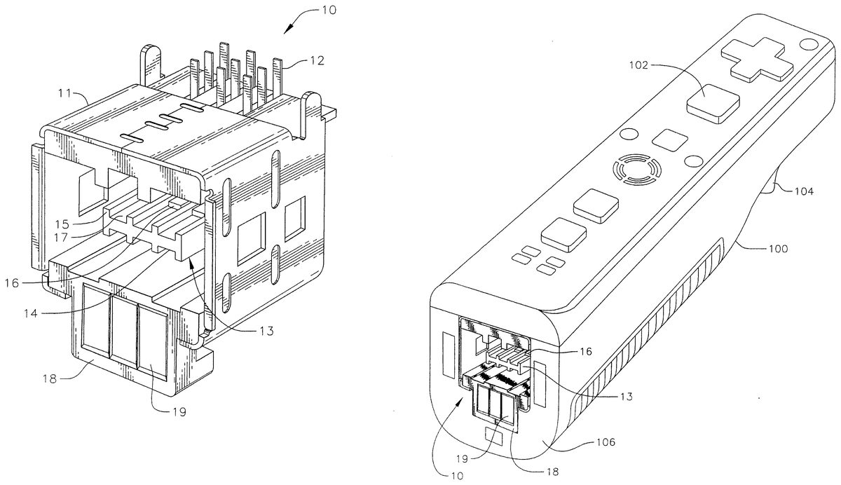
FIG. 1is a front perspective view of a female connector10for a video game controller according to an embodiment of the present invention. The female connector10includes a generally cubical case11and a plurality of pins12protruding from a top side of the case11for electrically connecting electrical contacts of the female connector10with electrical circuitry (i.e., electronic circuitry) of a host device (e.g., video game controller, auxiliary video game controller or a video game accessory).
The electrical circuitry may include one or more of a motor for generating vibrations or rumble, a microprocessor or microcontroller for controlling operations of the host device including user interface such as converting button press to electrical signals and light indications, a speaker, a microphone, logic circuitry, communication (e.g., wireless communication) circuitry, motion/orientation sensors, memory and/or the like, as those skilled in the art would appreciate. InFIG. 1, the female connector10includes nine pins that are arranged in a 3×3 matrix, but the present invention is not limited thereto. The pins may be formed of suitable conductive metal, for example, copper, aluminum or the like. The case11may be formed of metal such as copper, aluminum, stainless steel or the like. The case includes an insulating material such as plastic, covering at least a portion of its inner surfaces or outer surfaces to prevent shorts.
The female connector10also includes a contact mount13in a cavity defined in the case11, and having a base14and a plurality of ribs15protruding from the base14. The base14has a substantially flat rectangular shape. The ribs15extend parallel to each other, and protrude from both surfaces of the base14so as to form a plurality of parallel channels17having a same size at both above and below the base14. In one exemplary embodiment ofFIG. 1, the base14has four ribs15(two ribs on respective edges of the base14and two ribs between the edge ribs) located thereon to define three channels on each side of the base14(for a total of six channels). The contact mount including the base14and the ribs15may be made of plastic or other insulating material, and may be formed as a single integrated piece.
The contact mount13has located thereon a plurality of primary contacts (or contact plates)16that are electrically coupled to the respective pins12. Because there are six channels17in the embodiment illustrated inFIG. 1(three on either surface of the base14), the contact mount13can support up to six primary contacts16. Only two of the primary contacts16are shown inFIG. 1as locations corresponding to four of the primary contacts are hidden from view by other components of the female connector10. The primary contacts16may be formed of suitable conductive metal, such as copper, aluminum or the like.
The female connector10also includes a protruding member18having a generally rectangular shape and a plurality of secondary contacts (or contact plates)19located thereon. The secondary contacts19are also electrically connected with the respective pins12. In one embodiment, when the female connector10is used in a video game controller, the primary contacts16are used to communicate via the respective pins12with an auxiliary video game controller or a video game accessory to transmit/receive such signals as directional movement signals, power, ground and the like. The secondary contacts19may be used to communicate via the respective pins12with the auxiliary video game controller or the video game accessory to receive key/button press signals, data, serial data, motor drive signals (e.g., vibration signals) and/or the like. The secondary contacts19may be formed of suitable conductive metal, such as copper, aluminum or the like.
While the female connector10according to one exemplary embodiment illustrated inFIG. 1has been described above, the present invention is not limited thereto. For example, the shape of the case, the shape and location of the contact mount, the number of primary contacts and secondary contacts, the number of pins, the functions of each of the contacts and pins, can all be different in other embodiments as those skilled in the art would appreciate. In these other embodiments, the contacts and pins are also used to communicate control and data signals such as analog or digital directional movement signals, motor drive signals, serial data signals, key/button press signals, data or audio signals, and/or power and ground.
Further, in the female connector10and other connectors (e.g., other female and male connectors), primary and secondary contacts (e.g., contacts16or19) are used for making electrical contacts for various different signals. These contact plates for electrical connection help to realize a modularized architecture in which physical contacts between contact plates of interfacing/engaging/mating connectors form an electrical connection. In embodiments of the present invention, such contact plates are used in both male and female connectors to form one or more electrical connections therebetween.
FIG. 2is a front view of the female connector10ofFIG. 1. All six of the primary contacts16mounted on the contact mount13are shown inFIG. 2.FIGS. 3,4,5and6are a side view, a rear view, a top view and a bottom view, respectively, of the female connector10ofFIG. 1.
FIG. 7is a front view of a female connector20for a video game controller according to another embodiment of the present invention. The female connector20is substantially the same as the female connector10ofFIG. 1, except that the female connector20includes a protruding member28on which four secondary contacts (or contact plates)29are located, on a case21. Those skilled in the art would appreciate that the number of pins12may be different to account for an additional electrical connection from the secondary contacts29. Also, those skilled in the art would appreciate that the control and data signals and power and ground carried by the pins12and the primary and secondary contacts16,29can include substantially the same signals, power and ground as those carried by the pins12and the primary and secondary contacts16,19of the female connector10inFIG. 1. The primary and secondary contacts16,29may be formed of suitable conductive metal, such as copper, aluminum or the like.
FIG. 8is a front view of a female connector30for a video game controller according to another embodiment of the present invention. The female connector30is substantially the same as the female connector10ofFIG. 1, except that the female connector30includes a protruding member38on which five secondary contacts (or contact plates)39are located, on a case31. Those skilled in the art would appreciate that the number of pins12may be different to account for additional electrical connections from the secondary contacts39. Also, those skilled in the art would appreciate that the control and data signals and power and ground carried by the pins12and the primary and secondary contacts16,39can include substantially the same signals, power and ground as those carried by the pins12and the primary and secondary contacts16,19of the female connector10inFIG. 1. The primary and secondary contacts16,39may be formed of suitable conductive metal, such as copper, aluminum or the like.
FIG. 9is a perspective view of a video game controller100including the female connector10ofFIG. 1.FIG. 10is a bottom view of the video game controller ofFIG. 9, showing the female connector10included in the video game controller100. The video game controller100may be any suitable video game controller that can interface with an auxiliary video game controller and/or a video game accessory. By way of example, the video game controller can be a WAND™ controller available from Nyko Technologies, Inc., but the present invention is not limited thereto.
For example, the control and data signals and power provided to the video game controller100can include analog or digital directional movement signals, motor drive signals (e.g., vibration signals), key/various button press signals, serial data signals, audio signals, power, ground and/or the like. In one embodiment, when corresponding key/button signal or signals are received through one or more secondary contacts19, the video game controller100may be commanded as though corresponding one or more keys or buttons have been pressed. In other words, for example, when receiving a signal corresponding to “button ‘A’ press” through the secondary contacts19, the video game controller100will send signals to the video game console corresponding to pressing of a button A102. Further, when receiving a signal corresponding to “button ‘B’ press”, through the secondary contacts19, the video game controller100will send signals to the video game console corresponding to pressing of a button B104.
The video game controller100illustrated inFIG. 9is a wireless video game controller that can be coupled to the video game console remotely without a wire. However, the present invention is not limited thereto, and the video game controller100may be a wired video game controller. Also, while the video game controller100can be physically and electrically coupled to an auxiliary video game controller or a video game accessory, the video game controller100can alternatively be physically and electrically connected to a dongle (i.e., wireless adapter) that is remotely coupled to an auxiliary video game controller or a video game accessory in a wireless manner.
While the video game controller100inFIGS. 9 and 10includes the female connector10ofFIGS. 1-6, the video game controller in other embodiments may alternatively include the female connector20ofFIG. 7, the female connector30ofFIG. 8or a female connector10′ ofFIG. 17described below. Alternatively, the video game controller in other embodiments may include a male connector that is a mating connector to one of the female connectors10,20,30or10′, which male connector is to be described below. In still other embodiments, the video game controller may use a female or male connector that has different shapes and/or different number of pins and contacts without departing from the spirit or scope of the present invention.
FIG. 11is a front perspective view of a video game accessory (or video game controller accessory)200including a male connector208for mating with the female connector10on the video game controller100ofFIG. 9.FIG. 12is a front view of the video game accessory200ofFIG. 11. The video game accessory200ofFIGS. 11-12is a pistol grip (a gun controller) for mounting the video game controller100thereon. The video game accessory200includes a grip204, a trigger202and a controller mount203. The controller mount203is configured to support the video game controller100, and the grip204is configured for a user to grab onto while playing a shooting game, for example. The trigger202is configured to be pulled by a user to give a shooting command control signal to the video game controller100. By way of example, in one embodiment, when the trigger202is pulled, the video game accessory200sends a control signal corresponding to pressing of the ‘B’ button104on the video game controller100, to the video game controller100.
The video game accessory200also includes a male connector208for physically and electrically coupling to the female connector10of the video game controller100. The male connector208has formed thereon a plurality of primary contacts (or contact plates)210for electrically coupling with the primary contacts16of the female connector10. In one embodiment, three primary contacts210are formed at each of both top and bottom inner surfaces of the male connector208to electrically couple with the six primary contacts16of the female connector10.
The male connector208also includes a plurality of secondary electrical contacts212. The electrical contacts212are spring loaded to press on the secondary contacts19of the female connector10for sufficient electrical connection. In one embodiment, the male connector208includes three secondary contacts212to electrically couple with the three secondary contacts19in the video game controller100ofFIG. 9. In other embodiments, the number of primary and/or secondary contacts may be different to electrically contact the primary and secondary contacts16,19ofFIG. 9. The primary and secondary contacts210,212may be formed of suitable conductive metal, such as copper, aluminum or the like.
In operation, for example, the primary contacts210may receive power, ground and other signals from the video game controller100through the primary contacts16. The secondary contacts212are used to transmit control signals to the video game controller100. For example, the control signals may include one or more of key/button press signals, motor drive signals, data signals, and/or the like. For instance, when the key/button press signals are provided to the video game controller100, the video game controller100may perceive them as a pressing of a corresponding key/button on the video game controller100. While the video game accessory200includes only six primary contacts210and the three secondary contacts212, in other embodiments, the number of primary and/or secondary contacts may be different to correspond to the number of primary/secondary contacts in the corresponding female connector.
In the embodiment ofFIGS. 11-12and other embodiments, the feature/function of generating electrical and/or digital signals for duplicating functions of a video game controller buttons/keys or switches can be assigned by a user to different buttons/keys, switches or other components on a video game accessory. By way of example, a user can assign trigger functions to the buttons or switches on a video game accessory (e.g., a gun grip) to customize how electrical and/or digital signals are generated/triggered by the accessory. The video game accessory may include mechanical, electromechanical or electrical switches that can be used by a user for such customization of signal generation/triggering functions.
FIG. 13is a front perspective view of another video game accessory (or video game controller accessory)300including a male connector208for mating with the female connector10on the video game controller100ofFIG. 9.FIG. 14is a front view of the video game accessory ofFIG. 13. The video game accessory300ofFIG. 13is a shot gun grip (a gun controller) for mounting the video game controller100thereon. The video game accessory300includes a grip304, a trigger302and a controller mount303. The controller mount303is configured to support the video game controller100, and the grip304is configured for a user to grab onto while playing a shooting game, for example. The video game accessory300also includes a holding member306for engaging and holding the video game controller100after it is placed on the controller mount303. The trigger302is configured to be pulled by a user to give a shooting command control signal to the video game controller100. By way of example, in one embodiment, when the trigger302is pulled, the video game accessory300sends a control signal corresponding to pressing of the ‘B’ button104on the video game controller100to the video game controller100.
The video game accessory300also includes a male connector208for physically and electrically coupling to the female connector10of the video game controller100. The male connector208has formed thereon a plurality of primary contacts210for electrically coupling with the primary contacts16of the female connector10. In one embodiment, three primary contacts210are formed at each of both top and bottom inner surfaces of the male connector208to electrically couple with the six primary contacts16of the female connector10.
The male connector208also includes a plurality of secondary electrical contacts212. The secondary electrical contacts212are spring loaded to press on the secondary contacts19of the female connector10for sufficient/suitable electrical connection. In one embodiment, the male connector208includes three secondary contacts212to electrically couple with the three secondary contacts19in the video game controller100ofFIG. 9. In other embodiments, the number of primary and/or secondary contacts may be different to electrically contact the primary and secondary contacts16,19ofFIG. 9.
In operation, for example, the primary contacts210may receive power, ground and other signals from the video game controller100through the primary contacts16. The secondary contacts212are used to transmit control signals to the video game controller100. For example, the control signals may includes key/button press signals, motor drive signals, data signals, and/or the like. For instance, when the key/button press signals are provided to the video game controller100, the video game controller100may perceive them as a pressing of a corresponding key/button on the video game controller100. While the video game accessory300includes only six primary contacts210and the three secondary contacts212, in other embodiments, the number of primary and/or secondary contacts may be different to correspond to the number of primary/secondary contacts in the corresponding female connector.
FIG. 15is a front perspective of a video game accessory400of another embodiment according to the present invention.FIG. 16is a front view of the video game accessory400ofFIG. 15. The video game accessory400ofFIG. 15is a type pad (e.g., keyboard) for mounting the video game controller100thereon. The video game accessory400includes key pads402for entering text, control and commands. The key pads402, for example, include all of the alphanumeric keys as well as other special keys. For example, the video game accessory400may be used for menu selection and/or web browsing using video game controller100communicating with a video game console (e.g., Wii, Xbox® 360 or PS3® video game console). By way of example, when the video game controller100is a WAND controller, shoulder buttons or other suitable buttons or switches on the video game accessory may be used as buttons replicating ‘A’ and ‘B’ buttons102,104on the video game controller100. In other words, by pressing shoulder buttons on the video game accessory400, the video game accessory400may send control signals (i.e., ‘A’ or ‘B’ button press signals) to the video game controller100.
The video game accessory400also includes a male connector208for physically and electrically coupling to the female connector10of the video game controller100. The male connector208has formed thereon a plurality of primary contacts210for electrically coupling with the primary contacts16of the female connector10. In one embodiment, three primary contacts210are formed at each of both top and bottom inner surfaces of the male connector208to electrically couple with the six primary contacts16of the female connector10.
The male connector208also includes a plurality of secondary electrical contacts212. The electrical contacts212are spring loaded to press on the secondary contacts19of the female connector10for sufficient/suitable electrical connection. In one embodiment, the male connector208includes three secondary contacts212to electrically couple with the three secondary contacts19in the video game controller100ofFIG. 9. In other embodiments, the number of primary and/or secondary contacts may be different to electrically contact the primary and secondary contacts16,19ofFIG. 9.
In operation, for example, the primary contacts210may receive power, ground and other signals from the video game controller100through the primary contacts16. The secondary contacts212are used to transmit control signals to the video game controller100. For example, the control signals may includes key/button press signals, motor drive signals, data signals, and/or the like. For instance, when the key/button press signals are provided to the video game controller100, the video game controller100may perceive them as a pressing of a corresponding key/button on the video game controller100. While the video game accessory400includes only six primary contacts210and the three secondary contacts212, in other embodiments, the number of primary and/or secondary contacts may be different to correspond to the number of primary/secondary contacts in the corresponding female connector.
FIG. 17is a bottom perspective view of a video game controller100′ including a female connector10′ of another embodiment according to the present invention. The female connector10′ of the video game controller100′ is substantially the same as the female connector10of the video game controller100, except that the female connector10′ includes a pair of additional contacts (or contact plates)40that are used to receive additional control signals from an external device, such as a video game accessory or an auxiliary video game controller. As can be seen inFIG. 17, the additional contacts40are formed on an insulated inner surface of the case11, and may be used to receive control signals for driving a motor (e.g., rumble or vibration signal). The contacts40may be formed of suitable conductive metal such as aluminum or copper, for example.
FIG. 18is a perspective view of a male connector208′ configured to mate with the female connector10′ on the video game controller100′ ofFIG. 17. The male connector208′ has substantially the same configuration as the male connector208ofFIG. 11, for example, except that it includes additional contacts (or contact plates)50for electrically coupling with the contacts40to provide control signals to the video game controller100′. The contacts50may be formed of suitable conductive metal such as aluminum or copper, for example.
FIG. 19is a block diagram of a video game accessory504coupled to a video game controller500and an auxiliary video game controller506according to another embodiment of the present invention. The video game accessory504may be a pistol grip similar to the video game accessories depicted inFIGS. 11 and 13, but may additionally have a mount support for mounting the auxiliary video game controller506in addition to the video game controller500that may be substantially similar to the video game controller100ofFIG. 9.
The video game controller500may be substantially similar to the video game controller100ofFIG. 9, and may be a WAND controller available from Nyko Technologies, Inc. The auxiliary video game controller506may be a KAMA controller with rumble available from Nyko Technologies, Inc. In one embodiment, the KAMA controller with rumble is wired; in other embodiments, the KAMA controller with rumble may be configured to communicate wirelessly with the video game controller500and/or the video game accessory504.
The video game accessory504provides a key/button press signal, and a motor drive signal to electric circuitry (i.e., electronic circuitry502) of the video game controller500. The electrical circuitry502may include one or more of a motor for generating vibrations or rumble, a microprocessor or microcontroller for controlling operations of the video game controller500including user interface such as converting button press to electrical signals and light indications, a speaker, a microphone, logic circuitry, communication (e.g., wireless communication) circuitry, motion/orientation sensors, memory and/or the like, as those skilled in the art would appreciate.
By way of example, the key/button press signal in one embodiment commands the electric circuitry502in the video game controller500to initiate operation as though one of the keys/buttons (e.g., ‘A’ or ‘B’ key or button) has been pressed. Here, the key/button press signal may be connected in parallel to A and B keys/buttons. In other words, these signals duplicate or simulate the functions of the A and B keys/buttons. Further, the motor drive signal causes the motor in the electric circuitry502to operate to generate vibrations. The motor drive signal may originate from the video game controller500and may be a synchronizing rumble signal to the video game accessory504and the auxiliary video game controller506. Here, the motor drive signal can be provided to the video game controller500by the video game accessory504, but it is not required. For example, in an exemplary embodiment, the video game accessory504(e.g., a gun grip) can have a motor for vibrations that can be operated by activating a switch (e.g., pressing a button or pulling a trigger). The video game accessory504can also send a motor drive signal to the video game controller500to drive the motor for vibrations in the video game controller500.
The video game controller500and the video game accessory504also have an Inter-Integrated Circuit (I2C) data bus interface therebetween in one embodiment. The I2C data bus has three signal wires for Serial Data (SDA), Serial Clock (SCL) and SIG VDD signals. SDA is a data signal, SCL is synchronization clock, and the SIG VDD is peripheral equipment detect signal. The video game accessory504also communicates with the auxiliary video game controller506over an I2C data bus. The video game accessory504in one embodiment supplies power (e.g., 3.3V DC power) to the auxiliary video game controller506to electrical circuitry therein and to the motor drive circuit508. The power may originate from the video game controller500or from the video game accessory504. For example, the video game controller500may provide power to the video game accessory504.
FIG. 20is a block diagram of the video game controller500coupled to the auxiliary video game controller506according to another embodiment of the present invention. The system depicted inFIG. 20is substantially similar to the one depicted inFIG. 19, except that the video game controller500and the auxiliary video game controller506operate together without a video game accessory. The video game controller500and the auxiliary video game controller506communicate with each other over an I2C data bus. The video game controller500provides power (e.g., 3.3V DC power) to the auxiliary video game controller506. The video game controller500also provides the motor drive signal to the motor drive circuit508in the auxiliary video game controller506.
FIG. 21is a perspective view and signal description of a female connector (or female plug)600of a video game controller according to another embodiment of the present invention. The video game controller may be a WAND controller. It can be seen inFIG. 21that the female connector600includes a plurality of pins: 1) GND, 2) KEY A, 3) GND, 4) SDA, 5) GND, 6) NC (not connected), 7) SIG VDD, 8) KEY B, 9) MOTO DEV, 10) VDC 3V and 11) SCL. The VDC 3V and GND pins are for providing power and ground to an external devices (e.g., an auxiliary video game controller). The SDA, SCL and SIG VDD pins are for an I2C data bus interface, wherein SDA is data signal, SCL is synchronizing clock, and SIG VDD is peripheral equipment detect signal. KEY A and KEY B are for receiving ‘A’ and ‘B’ button press signals. The MOTO DEV pin is for providing a motor drive signal. The female connector600also includes secondary contacts for KEY A and KEY B signals and GND. The secondary contacts KEY A and KEY B are for receiving button press signals to be transmitted to the respective pins.
In one embodiment, the I2C data bus interface sends and receives bi-directional signals, the KEY A,B signals are for receiving button press signal input, and the motor drive signal is an output signal. Further, in a particular embodiment, the power of VDC 3V and GND are provided as an output by the video game controller. As indicated by the signal directions (bi-directional arrows) inFIG. 21, however, one or more of the I2C data bus signals, KEY A,B signals, Motor drive signals and Power can be provided in a single direction and/or bi-directional manner (i.e., can receive and/or transmit over the same contacts or contact plates) in other embodiments, depending on the operation mode and/or configuration of the video game controller and the video game accessory and/or the auxiliary video game controller coupled to the video game controller.
FIG. 22is a perspective view and signal description of a male connector (or male plug)700of a video game accessory according to another embodiment of the present invention. The video game accessory may be a gun controller or a pistol grip. The male connector700, for example, may be substantially similar to the male connector208′ ofFIG. 20. The male connector700has secondary contacts (pins) for outputting KEY A, KEY B and GND signals. The male connector700also includes pins SDA, SCL and SIG VDD for an I2C data bus interface. The male connector700also includes GND and VDC 3V contacts for receiving power, and also has a non-connected (NC) pin. The connector700also sends out GND and MOTO DEV for sending motor signals. As indicated by the signal directions (bi-directional arrows) inFIG. 22, one or more of the I2C data bus signals, KEY A,B signals, Motor drive signals and Power can be provided in a single direction and/or bi-directional manner (i.e., can receive and/or transmit over the same contacts or contact plates) in other embodiments, depending on the operation mode and/or configuration of the video game accessory and the video game controller and/or the auxiliary video game controller coupled to the video game accessory.
FIG. 23is a perspective view and signal description of a male connector (or male plug) of an auxiliary video game controller800according to another embodiment of the present invention. The auxiliary video game controller800may be a KAMA controller with rumble. The male connector800, for example, may be substantially similar to the male connector208′ ofFIG. 20. The male connector800includes pins SDA, SCL and SIG VDD for an I2C data bus interface. The male connector800also includes GND and MOTO DEV for receiving motor drive signals, and also has a non-connected (NC) pin. The male connector800receives power and ground from an external device through VDC 3V and GND contacts, respectively. As indicated by the signal directions (bi-directional arrows) inFIG. 23, one or more of the I2C data bus signals, Motor drive signals and Power can be provided in a single direction and/or bi-directional manner (i.e., can receive and/or transmit over the same contacts or contact plates) in other embodiments, depending on the operation mode and/or configuration of the auxiliary video game controller and the video game controller and/or the video game accessory coupled to the auxiliary video game controller.
While this invention has been described in connection with certain exemplary embodiments, it is to be understood that the invention is not limited to the disclosed embodiments, but, on the contrary, is intended to cover various modifications and equivalent arrangements included within the spirit and scope of the appended claims and their equivalents. The invention(s) of the present application also covers all other embodiments disclosed herein that will be claimed in a non-provisional application as well as any divisional and/or continuation applications.
Claims
- A connector of a handheld video game controller, the handheld video game controller for controlling a video game console and comprising electrical circuitry and a plurality of buttons comprising a first button and a second button, the connector being for connecting to a video game accessory and comprising: a case having a cavity and a contact mount in the cavity;a protruding member attached to the case;a plurality of contacts for receiving and transmitting a plurality of electrical signals with the video game accessory, the plurality of contacts comprising primary contacts on the contact mount and secondary contacts on the protruding member;and a corresponding plurality of pins protruding from a side of the case and electrically coupled to respective ones of the plurality of contacts, the plurality of pins being for communicating the electrical signals with the electrical circuitry of the handheld video game controller, wherein the secondary contacts comprise a first contact for receiving a first electrical signal from the video game accessory that corresponds to pressing the first button, from among the plurality of electrical signals, and transmitting the first electrical signal to the electrical circuitry via a first one of the plurality of pins, the transmitting of the first electrical signal causing the handheld video game controller to send a first command to the video game console as if the first button had been pressed, and wherein the secondary contacts further comprise a second contact for receiving a second electrical signal from the video game accessory that corresponds to pressing the second button, from among the plurality of electrical signals, and transmitting the second electrical signal to the electrical circuitry via a second one of the plurality of pins, the transmitting of the second electrical signal causing the handheld video game controller to send a second command to the video game console as if the second button had been pressed.
- The connector of claim 1 , wherein the plurality of electrical signals comprises at least one of a motor drive signal or a serial data signal.
- The connector of claim 1 , wherein an insulation is on one of inner surfaces of the case, and the plurality of contacts comprises additional contacts on the insulation.
- The connector of claim 3 , wherein at least one of the additional contacts is configured to receive a motor drive signal to initiate vibration.
- The connector of claim 1 , wherein the connector is configured to remap one or more buttons, keys, switches, triggers, wheels, and/or sticks of the video game accessory to one or more of the plurality of buttons of the video game controller.
- A handheld video game controller for controlling a video game console and comprising: electrical circuitry;a plurality of buttons comprising a first button and a second button;and a connector for connecting to a video game accessory and comprising: a case having a cavity and a contact mount in the cavity;a protruding member attached to the case;a plurality of contacts for receiving and transmitting a plurality of electrical signals with the video game accessory, the plurality of contacts comprising primary contacts on the contact mount and secondary contacts on the protruding member;and a corresponding plurality of pins protruding from a side of the case and electrically coupled to respective ones of the plurality of contacts, the plurality of pins being for communicating the electrical signals with the electrical circuitry, wherein the secondary contacts comprise a first contact for receiving a first electrical signal from the video game accessory that corresponds to pressing the first button, from among the plurality of electrical signals, and transmitting the first electrical signal to the electrical circuitry via a first one of the plurality of pins, the transmitting of the first electrical signal causing the handheld video game controller to send a first command to the video game console as if the first button had been pressed, and wherein the secondary contacts further comprise a second contact for receiving a second electrical signal from the video game accessory that corresponds to pressing the second button, from among the plurality of electrical signals, and transmitting the second electrical signal to the electrical circuitry via a second one of the plurality of pins, the transmitting of the second electrical signal causing the handheld video game controller to send a second command to the video game console as if the second button had been pressed.
- The video game controller of claim 6 , wherein the plurality of electrical signals comprises at least one of a motor drive signal or a serial data signal.
- The video game controller of claim 6 , wherein an insulation is on one of inner surfaces of the case, and the plurality of contacts comprises additional contacts on the insulation.
- The video game controller of claim 8 , wherein at least one of the additional contacts is configured to receive a motor drive signal to initiate vibration.
Disclaimer: Data collected from the USPTO and may be malformed, incomplete, and/or otherwise inaccurate.