U.S. Pat. No. 8,602,888
Video game device and image processing program
AssigneeNintendo Co., Ltd.
Issue DateJune 28, 2005
Illustrative Figure
Abstract
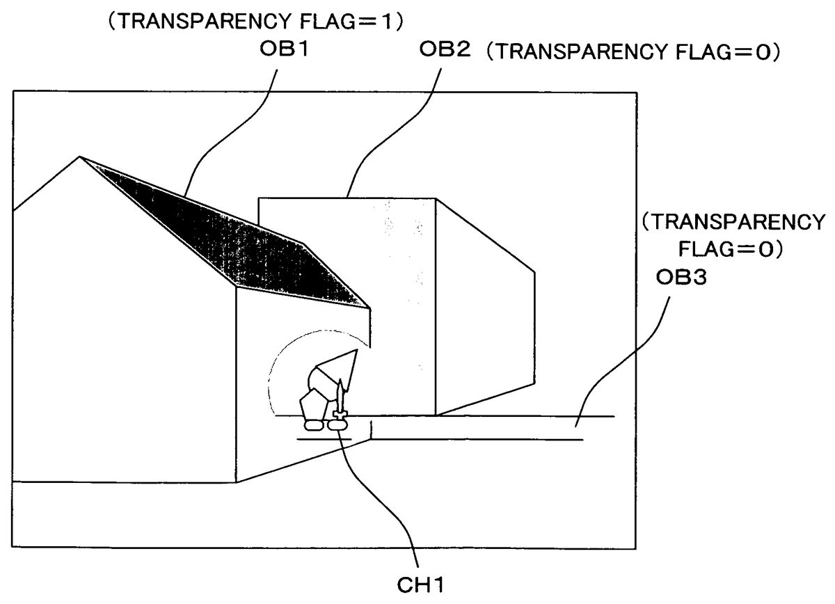
A character object CH1 is first projected onto a screen plane, and a masked area is rendered as a circular area that is centered about the position of the character object CH1 projected onto the screen plane. The obtained image data is stored in a main memory as mask data, and is used when rendering each object in a virtual game space. A transparency flag is set in advance for each of field objects OB1 to OB3. The field object OB1 whose transparency flag is “1” is rendered by using the mask data, whereas the character object CH1 and the field objects OB2 and OB3 whose transparency flag is “0” are rendered normally. Thus, it is possible to provide a video game device capable of displaying a particular object such as the player character so that it can always be seen, with minimum detraction from the atmosphere of the game field.
Description
DESCRIPTION OF THE PREFERRED EMBODIMENTS (First Embodiment) A video game system according to one embodiment will now be described with reference to the drawings. FIG. 1generally shows a video game system according to one embodiment. Referring toFIG. 1, a video game system10includes a monitor12, a video game machine14, an optical disk16, a memory card18and a controller20. The optical disk16and the external memory card18are inserted in the video game machine14. The controller20is connected, via a connection cable, to the connector of one of a plurality (four inFIG. 1) of controller ports of the video game machine14. The monitor12is connected to the video game machine14via an AV cable, or the like. Note that the connection between the video game machine14and the controller20may be a wireless connection. The controller20is an input device with which the player gives inputs to the video game, and includes a plurality of control switches. The controller20outputs, to the video game machine14, operation data indicating the state of the control switches. By operating the controller20, the player can make the player character to move or do an action in the video game. The optical disk16statically stores a game program and game data. The optical disk16is inserted in the video game machine14when the player plays the video game. Instead of the optical disk16, the means for storing the game program, etc., may be any other suitable external storage medium such as, for example, a DVD-ROM, a CD-ROM, an MO disk, a memory card or a ROM cartridge. The video game machine14reads out the game program recorded on the optical disk16, and performs various processes according to the game program. The monitor12displays a game image on the screen based on a video signal outputted from the video game machine14. The monitor12includes a speaker22, and the speaker22outputs game sound based on a ...
DESCRIPTION OF THE PREFERRED EMBODIMENTS
(First Embodiment)
A video game system according to one embodiment will now be described with reference to the drawings.
FIG. 1generally shows a video game system according to one embodiment. Referring toFIG. 1, a video game system10includes a monitor12, a video game machine14, an optical disk16, a memory card18and a controller20. The optical disk16and the external memory card18are inserted in the video game machine14. The controller20is connected, via a connection cable, to the connector of one of a plurality (four inFIG. 1) of controller ports of the video game machine14. The monitor12is connected to the video game machine14via an AV cable, or the like. Note that the connection between the video game machine14and the controller20may be a wireless connection.
The controller20is an input device with which the player gives inputs to the video game, and includes a plurality of control switches. The controller20outputs, to the video game machine14, operation data indicating the state of the control switches. By operating the controller20, the player can make the player character to move or do an action in the video game.
The optical disk16statically stores a game program and game data. The optical disk16is inserted in the video game machine14when the player plays the video game. Instead of the optical disk16, the means for storing the game program, etc., may be any other suitable external storage medium such as, for example, a DVD-ROM, a CD-ROM, an MO disk, a memory card or a ROM cartridge.
The video game machine14reads out the game program recorded on the optical disk16, and performs various processes according to the game program.
The monitor12displays a game image on the screen based on a video signal outputted from the video game machine14. The monitor12includes a speaker22, and the speaker22outputs game sound based on a sound signal outputted from the video game machine14.
The memory card18includes, as a backup memory, a rewritable storage medium such as a flash memory, which stores saved game data, or the like.
FIG. 2is a block diagram showing an internal configuration of the video game machine14. Various components of the video game machine14will now be described in greater detail with reference toFIG. 2.
The video game machine14includes a CPU24and a memory controller34connected to the CPU24. The memory controller34is connected to a GPU (Graphics Processing Unit)26, a main memory28, a DSP (Digital Signal Processor)30and various interfaces. The memory controller34controls the data transfer between these components.
At the start of the game, a disk drive46first drives the optical disk16inserted in the video game machine14. The game program stored in the optical disk16is loaded into the main memory28via a disk I/F (interface)44and the memory controller34. The game program loaded in the main memory28is executed by the CPU24to start a game. After the start of the game, the player makes inputs using the controller19, in response to which the controller20outputs the corresponding operation data to the video game machine14. The operation data outputted from the controller20is inputted to the CPU24via a controller I/F36and the memory controller34. The CPU24performs the game process based on the input operation data. The game image is produced primarily by the GPU26, and the game sound is produced primarily by the DSP30. An ARAM (Audio RAM)32is used to store an audio signal.
The GPU26performs operations on the coordinates of each object in the 3D virtual game space (e.g., rotation, enlargement/shrinking or deformation of the object, and coordinate transformation from world coordinates to camera coordinates or screen coordinates), and renders the object being projected onto the screen plane based on texture data, etc. (by determining the color of each of the pixels corresponding to the object and writing the color in the color buffer), thus producing the game image. The color buffer is a memory area that is reserved for storing game image data (RGB data) to be displayed on the monitor12. The GPU26produces a game image by using other buffers in addition to the color buffer, as necessary, including a z-buffer for storing the distance from the viewpoint to each object rendered in the color buffer, and a stencil buffer for the shadow volume algorithm.
FIG. 3andFIG. 4show the memory map of the main memory28. Specifically,FIG. 3is a memory map for programs, andFIG. 4is a memory map for data.
Referring toFIG. 3, a game main program48, an object movement control program50and an image processing program52are loaded from the optical disk16into the main memory28.
The object movement control program50is a program for moving an object in the 3D virtual game space according to a predetermined algorithm or in response to user instructions. The image processing program52includes a mask producing program54, a projection program56, a rendering program58and a display control program60. The mask producing program54is a program for instructing the CPU24or the GPU26to produce mask data to be described later. The projection program56is a program for instructing the CPU24or the GPU26to project an object in the virtual game space onto a predetermined screen plane. Methods of projection include a perspective projection and a parallel projection. The rendering program58is a program for instructing the CPU24or the GPU26to render an object in the virtual game space (i.e., write the colors of the object in the color buffer). The display control program60is a program for instructing the CPU24or the GPU26to periodically output a video signal to the monitor12based on the image data stored in the color buffer.
Referring toFIG. 4, the main memory28includes an area used as an operation data buffer62, an area used as a color buffer64, an area for storing data of character objects, an area for storing data of field objects, an area for storing mask data86to be described later, and an area for storing other data.
The operation data buffer62is a memory area for temporarily storing operation data outputted from the controller20. The color buffer64is a memory area for temporarily storing color data of a game image displayed on the monitor12.
A character object is an object representing a character in the virtual game space, and may be a player character controlled by the player or a non-player character controlled by the computer, but not by the player, according to the movement of the player character. It is assumed in the present embodiment that there are a plurality of character objects (CH1, CH2, CH3, . . . ) in the virtual game space. The main memory28stores, for each character object, position data66representing the position (3D coordinates) of the character object in the virtual game space, polygon data68defining the shape of the character object, and texture data70defining the surface texture of the character object.
A field object is one of the objects that together form the field of the virtual game space, and may be a building, a wall, the ground, a street, etc., in the virtual game space. It is assumed in the present embodiment that there are a plurality of field objects (OB1, OB2, OB3, . . . ) in the virtual game space. The main memory28stores, for each field object, position data78representing the position (3D coordinates) of the field object in the virtual game space, polygon data80defining the shape of the field object, texture data82defining the surface texture of the field object, and a transparency flag84to be described later.
FIG. 5andFIG. 6each show an example of a game screen according to a first embodiment.FIG. 5shows the character object CH1and the field objects OB1to OB3arranged in the virtual game space. When the character object CH1moves in the direction indicated by an arrow inFIG. 5, a predetermined area of the field object OB1that is centered about the character object CH1is made transparent as shown inFIG. 6. Thus, even if the character object CH1moves behind the field object OB1, the user can see the character object CH1.
Now, the processes of the CPU24or the GPU26performed based on the programs shown inFIG. 3will be described with reference to flow charts ofFIG. 7toFIG. 9.
Referring toFIG. 7, after the main process is started, the process first goes to step S10, where an initialization process is performed. In this process, the viewpoint, the position of each object, the position of the light source, etc., in the virtual game space are initialized. In step S12, operation data outputted from the controller20is stored in the operation data buffer62. In step S14, the position of each object in the virtual game space is updated based on the object movement control program50ofFIG. 3. Specifically, if the character object CH1is a player character, which is controlled based on the player's operation of the controller20, the position of the character object CH1is updated based on the operation data stored in the operation data buffer62in step S12. Of course, the character object CH1may alternatively be a non-player character attacking the player character, for example. Then, the position of the character object CH1is updated based on a stored program according to the position of the player character.
In step S16, a mask producing process is performed based on the mask producing program shown inFIG. 3. The details of the mask producing process will be described later. In step S18, a rendering process is performed based on the rendering program58shown inFIG. 3, whereby a game image to be displayed on the monitor12is stored in the color buffer64. The details of the rendering process will also be described later. In step S20, a video signal based on the game image stored in the color buffer64is outputted to the monitor12based on the display control program60shown inFIG. 3, whereby the game image is displayed on the screen of the monitor12. In step S22, it is determined whether or not the game is over. If the game is not over, the process returns back to step S12. While the game is not over, steps S12to S18are repeated with a 1/30-second period, for example.
Now, the details of the mask producing process will be described with reference to the flow chart ofFIG. 8. It is assumed herein that the viewpoint and the objects (the character object CH1and the field objects OB1to OB3) are arranged in the virtual game space as shown inFIG. 10.FIG. 10shows the game space as viewed from a direction vertical to the line of sight. Referring toFIG. 10, objects that are contained within the space defined between the near clipping plane and the far clipping plane (the viewing volume) are to be displayed. While objects are rendered by a perspective projection in the example ofFIG. 10, the present invention is not limited to this, and objects may be rendered by a parallel projection. It is assumed herein that the transparency flag84is “1” for the field object OB1and “0” for the field object OB2and the field object OB3, as shown inFIG. 6.
After the mask producing process is started, the process first goes to step S24, where each character object (the character object CH1in the example ofFIG. 5) is projected onto the screen plane defined in the virtual game space based on the projection program56ofFIG. 3. Specifically, the position coordinates (3D coordinates) of each character object in the 3D virtual game space are subjected to a perspective projection transformation based on the viewpoint to obtain coordinates (2D coordinates) of the character object on the display screen of the monitor12. While the screen plane is used as the near clipping plane in the example ofFIG. 10, the exemplary embodiment presented herein is not limited to this. The projection operation is typically done by subjecting vertex coordinates of each polygon of each character object to a coordinate transformation using a predetermined transformation matrix.FIG. 11shows the character object CH1being projected onto the screen plane. While each polygon of the character object CH1is projected onto the screen plane in the illustrated example, the present invention is not limited to this, and only a point indicating the position of the character object CH1may be projected onto the screen plane.
In step S26, monochrome image data as shown inFIG. 12is produced based on the position of each character object projected onto the screen plane. Specifically, the process renders a circular area (masked area) as shown inFIG. 12that is centered about the position of each character object projected onto the screen plane. The color buffer64may be temporarily used for the rendering of the masked area.
In step S28, image data obtained in step S26is stored in the main memory28as mask data. The resolution of image data stored as mask data does not have to be the same as that of the game image, but the image data may be stored in the main memory28after the resolution thereof is lowered from that of the game image. Then, it is possible to save the memory area of the main memory28required for storing mask data. When mask data with a lowered resolution is used in the rendering process to be described later, the resolution of the mask data stored in the main memory28can be converted to that of game image.
Now, the details of the rendering process will be described with reference to the flow chart ofFIG. 9.
After the rendering process is started, the process first goes to step S30, where an object to be rendered in the color buffer is determined. While the order in which objects are rendered is arbitrary, objects may be rendered in a predetermined order as necessary. For example, by rendering opaque objects first and then semi-transparent objects, the semi-transparency operation (alpha blending) may be facilitated. For example, by first rendering objects farther away from the viewpoint and then closer objects, hidden-surface removal is achieved without performing a z-test using the z-buffer.
In step S32, it is determined whether or not the object to be rendered as determined in step S30is a character object. The process proceeds to step S38if the object is a character object, and to step S34otherwise (i.e., if it is a field object).
In step S34, it is determined with reference to the main memory28whether or not the transparency flag84of the field object to be rendered is “0”. The process proceeds to step S38if the transparency flag84is “0”, and to step S36otherwise (i.e., if is “1”).
In step S36, the object to be rendered (a field object whose transparency flag is “1”) is rendered by using the mask data86stored in the main memory28in the mask producing process. The transparency of each pixel of the object to be rendered is determined based on the value of each pixel of a mask image (an image of the masked area) included in the mask data86for one screen. Specifically, when an object in the 3D virtual game space is rendered in the color buffer64through a perspective projection transformation, the process refers to the mask data86stored in the main memory28so that the transparency of a portion of the object that overlaps with the masked area is changed to 100% (whereby the portion contained within the masked area is not rendered in the color buffer64) while the transparency is not changed for the rest of the object (whereby the rest of the object is displayed normally). For example, with the mask data ofFIG. 12, the field object OB1will be rendered as shown inFIG. 13.
In step S38, the object to be rendered (a character object or a field object whose transparency flag is “0”) is rendered normally, i.e., without referring to the mask data86stored in the main memory28in the mask producing process.
In step S40, it is determined whether or not the rendering process is completed (i.e., whether or not all of the objects contained within the viewing volume have been rendered). If the rendering process is not complete, the process returns back to step S30to determine and render the next object. If the rendering process is complete, the process proceeds to step S20ofFIG. 7, where a game image as shown inFIG. 6, for example, is displayed on the monitor12.
While a portion of an object contained within the masked area is not rendered at all in the present embodiment, the exemplary embodiment presented herein is not limited to this. For example, a portion of an object contained within the masked area may be made semi-transparent. In such a case, the alpha value (a value that determines the transparency) of a portion of an object contained within the masked area can be changed to an appropriate value, before performing an alpha blending operation based on the changed alpha value.
While binary image data as shown inFIG. 12is used as mask data in the present embodiment, the exemplary embodiment presented herein is not limited to this, and image data with more gray levels may be used.FIG. 14shows an example where the mask data is image data using four different values for different transparencies. Specifically, in the mask data shown inFIG. 14, the transparency of the object is gradually varied around the boundary of the masked area.FIG. 15shows the field object OB1rendered by using the mask data. The transparency (alpha value) of the field object OB1is changed according to the value of the mask data, and a game image as shown inFIG. 16is produced through an alpha blending operation based on the changed alpha value. In the example ofFIG. 16, a portion of the field object OB1around the boundary of the masked area has gradually varying transparencies. Such a game image will appear more elegant and beautiful than that ofFIG. 6.
While a circular masked area is used in the present embodiment, the exemplary embodiment presented herein is not limited to this, and the masked area may be of any other suitable shape (e.g., elliptical, rectangular or star-shaped).
The size of the masked area may be fixed, or may change according to the size or state of the character object. The size of the masked area may be changed according to the distance from the viewpoint to the character object. Particularly, where a game image is produced by a perspective projection, it is preferred that the size of the masked area is reduced as the character object moves away from the viewpoint as shown inFIG. 17BandFIG. 17Cwhen the character object moves in the direction indicated by an arrow inFIG. 17A, for example. Then, it is possible to obtain a sophisticated game image while the character object can always be seen.
There is only one masked area inFIG. 12since there is only one character object being projected onto the screen plane in the example ofFIG. 11. Where there are a plurality of character objects as shown inFIG. 18, a plurality of masked areas are produced in the mask data corresponding to the plurality of character objects (the character objects CH1and CH2in the illustrated example) as shown inFIG. 19. By rendering a field object whose transparency flag is “1” (the field object OB1in the illustrated example) by using the mask data ofFIG. 19, a game image as shown inFIG. 20is obtained.
While the transparency flag84is set to be “1” for the field object OB1and “0” for the field objects OB2and OB3ofFIG. 10in the present embodiment, the value of the transparency flag of each field object is appropriately determined in advance in view of the position of the field object and the viewpoint. For example, the transparency flag is set to be “0” for a field object representing the ground since a character object will not usually be hidden behind the ground. In contrast, the transparency flag is set to be “1” for a field object representing something located at a higher position than a character object (e.g., a sail of a ship) since such an object is likely to be hiding the character object if the viewpoint is located above the character object. The transparency flag may be set to be “0” for a field object that is smaller than a character object or a field object that is semi-transparent since it is unlikely that such an object will significantly block the view of the character object.
If it is acceptable that the game image might look awkward, all field objects may be subjected to the masking process using mask data, without using transparency flags. An advantage of this is that the character object will at least be seen at any time.
As described above, according to the first embodiment, mask data is produced based on the position of a character object, and field objects are subjected to the masking process using the produced mask data, whereby the character object can always be seen.
(Second Embodiment)
A second embodiment will now be described.
Consider a case where a plurality of objects (the character objects CH1to CH3and the field objects OB1and OB2) are arranged in the 3D virtual game space as shown inFIG. 21. It is assumed that the transparency flag is “1” for the field object OB1and “0” for the field object OB2. If the scene as viewed from a viewpoint A ofFIG. 21is rendered by the method of the first embodiment, a game image as shown inFIG. 22will be obtained. In the game image ofFIG. 22, the character objects CH1to CH3are displayed appropriately. However, if the scene as viewed from a viewpoint B ofFIG. 21is rendered by the method of the first embodiment, the character objects CH1and CH2will not be displayed as shown inFIG. 23. Moreover, a portion of the field object OB1is omitted unnecessarily due to the masked area corresponding to the character object CH1, resulting in an awkward game image. The second embodiment solves such a problem.
In the second embodiment, the masking process using mask data is performed only on field objects that are closer to the viewpoint than a predetermined reference position. The reference position may be defined as an absolute position in the virtual game space, as a relative position with respect to the viewpoint, or as the position of a particular character object.
For example, consider a case where a plurality of objects (the character objects CH1to CH3and the field objects OB1and OB2) are arranged in the virtual game space as shown inFIG. 24with a reference position being defined as shown inFIG. 24.
When rendering the scene as viewed from the viewpoint A ofFIG. 24, mask data is produced based on the positions of the character objects CH1to CH3. The field object OB1, which is closer to the viewpoint (the viewpoint A) than the reference position, is subjected to the masking process using the mask data, while the field object OB2, which is farther away from the viewpoint than the reference position, is rendered normally. As a result, a game image as shown inFIG. 25is obtained.
When rendering the scene as viewed from the viewpoint B ofFIG. 24, mask data is produced based on the positions of the character objects CH1to CH3. The field object OB2, which is closer to the viewpoint (the viewpoint B) than the reference position, is subjected to the masking process using the mask data, while the field object OB1, which is farther away from the viewpoint than the reference position, is rendered normally. As a result, a game image as shown inFIG. 26is obtained.
In the game images ofFIG. 25andFIG. 26, the character objects CH1to CH3are all displayed, and no portion of any field object that is farther away from the viewpoint than a character object is omitted unnecessarily.
The details of the operation of the second embodiment will now be described while focusing on what is different from the first embodiment.
In the second embodiment, a reference position88as described above is stored in the main memory28as shown inFIG. 27. It is assumed that the reference position is defined as the distance from the viewpoint.
The rendering process of the second embodiment will now be described with reference to the flow chart ofFIG. 28. Note that the flow chart ofFIG. 28only shows a portion of the rendering process, and the remaining steps are as shown in the flow chart ofFIG. 9. Moreover, like steps in the flow chart ofFIG. 28to those in the flow chart ofFIG. 9are denoted by like reference numerals.
After an object to be rendered is determined in step S30ofFIG. 9, it is determined in step S32ofFIG. 28whether or not the object to be rendered is a character object. The process proceeds to step S38if the object is a character object, and to step S34otherwise (i.e., if it is a field object).
In step S42, it is determined with reference to the main memory28whether or not the field object to be rendered is closer to the viewpoint than the reference position88. The process proceeds to step S36if the field object to be rendered is closer to the viewpoint than the reference position88, and to step S38otherwise (i.e., if it is farther away from the viewpoint than the reference position88).
In step S36, the object to be rendered (a field object that is closer to the viewpoint than the reference position88) is rendered by using the mask data86stored in the main memory28in the mask producing process.
In step S38, the object to be rendered (a character object or a field object that is farther away from the viewpoint than the reference position88) is rendered normally.
Through a rendering process as described above, game images as shown inFIG. 25andFIG. 26are produced.
While the reference position is defined as the distance from the viewpoint in the present embodiment, the exemplary embodiment presented herein is not limited to this. For example, the reference position may be defined as the position of a particular character object, as mentioned above. In such a case, the reference position88stored in the main memory28needs to be updated as the particular character object moves.
Where there are a plurality of character objects (the character objects CH1to CH4in the illustrated example) in the virtual game space as shown inFIG. 29, it is preferred that the reference position is defined as the position of one of the character objects contained within the viewing volume (the character objects CH1to CH3in the illustrated example) that is farthest away from the viewpoint (the character object CH3in the illustrated example). Thus, all of the character objects contained within the viewing volume will be displayed, and it is possible to obtain a game image that is not awkward (i.e., no portion of the field object OB3is omitted in the example ofFIG. 29). This can be realized by performing steps S44to S46ofFIG. 30before the rendering process in step S18ofFIG. 7. Specifically, in step S44, the process obtains the position of one of the character objects contained within the viewing volume that is farthest away from the viewpoint. In step S46, the position of the character object obtained in step S44(the position may be an absolute position in the virtual space or a relative position with respect to the viewpoint) is stored in the main memory28as the reference position88.
The method of the first embodiment and that of the second embodiment may be combined together. Specifically, the masking process using mask data may be performed only for field objects that are closer to the viewpoint than the reference position and whose transparency flag is “1”, while not performing the masking process for the other field objects.
(Third Embodiment)
A third embodiment will now be described.
Consider a case where a plurality of objects (the character objects CH1to CH3and the field objects OB1and OB2) are arranged in the 3D virtual game space as shown inFIG. 31. With such an arrangement, it is not possible, using the method of the first embodiment or that of the second embodiment, to obtain a game image in which the character object CH3is displayed while portions of the field object OB2that are behind the character objects CH1and CH2are not omitted unnecessarily. The third embodiment solves such a problem.
In the third embodiment, the process produces mask data as shown inFIG. 12,FIG. 14orFIG. 19with depth information being added thereto, and performs the masking process using such mask data.
FIG. 32shows the principle of the third embodiment. For each masked area of mask data as shown inFIG. 12,FIG. 14orFIG. 19, depth information according to the position of each character object is added, whereby it is possible to define a masked space extending from each of the character objects (the character objects CH1to CH3) to the viewpoint, as shown inFIG. 32. Referring toFIG. 33, a masked space is a space extending from the position of a character object in the virtual game space to the viewpoint. The shape of a masked space is basically a conical shape where objects are rendered by a perspective projection, and is basically a columnar shape where objects are rendered by a parallel projection. Based on the mask data, the rendering process renders a portion of a field object within the masked space transparent (or semi-transparent) while rendering the rest of the field object normally, as shown inFIG. 33.
FIG. 34shows an example of mask data produced in the third embodiment. While the mask producing process of the third embodiment renders a masked area based on the position of each character object projected onto the screen plane as in the first embodiment, the depth of the color of the masked area is determined according to the depth of the masked space (i.e., the distance from the viewpoint to the corresponding character object). In the example ofFIG. 34, the depth of the color of the masked area increases as the depth of the masked space increases. The depth of the color of a masked area may have any number of levels. Note that the depth of the color of a masked area in the mask data ofFIG. 12orFIG. 14represents the transparency, whereas the depth of the color of a masked area in the mask data ofFIG. 34represents the depth of the masked space. In the mask data ofFIG. 34, the size of each masked area may also be varied so that it is possible to realize an image as shown inFIG. 17. Specifically, the masked area can be rendered smaller as the depth of the masked space increases. Thus, it is possible to realize a more sophisticated game image. Wherever necessary, mask data defining the transparency as shown inFIG. 12orFIG. 14will be referred to as “color mask data”, distinguished from mask data defining the depth of a masked space as shown inFIG. 34, which will be referred to as “depth mask data”.
In the rendering process, the field objects OB1and OB2are rendered by using mask data as shown inFIG. 34. Specifically, the field objects OB1and OB2are rendered so that any portion of the field objects OB1and OB2that is contained within any masked space will be rendered with a transparency of 100% (i.e., such a portion is not rendered in the color buffer64) while the remaining portion will be rendered with a transparency of 0% (i.e., it is rendered normally). As a result, a game image as shown inFIG. 35is obtained. In the game image ofFIG. 35, the character object CH3is displayed while portions of the field objects OB1and OB2that are behind the character objects CH1and CH2are not omitted unnecessarily.
The details of the mask producing process of the third embodiment will now be described with reference to the flow chart ofFIG. 36.
In step S24, each character object is projected onto the screen plane as in the first and second embodiments. In step S26, the position of each masked area is determined based on the position of each character object on the screen plane. In step S28, the process determines the depth of the color of each masked area in the mask data according to the distance from the viewpoint to the corresponding character object. In step S30, the masked area is rendered based on the determination results from step S26and step S28. In step S32, image data obtained in step S30is stored in the main memory28as mask data.
The details of the rendering process of the third embodiment will now be described with reference to the flow chart ofFIG. 37.FIG. 37differs fromFIG. 9in that step S34is absent and step S36is replaced by step S56. Therefore, steps other than step S56will not be described below.
It is determined in step S32whether or not an object to be rendered is a character object, and the process proceeds to step S56if it is not a character object (i.e., if it is a field object). In step S56, the object to be rendered (a field object) is rendered by using the mask data86stored in the main memory28in mask producing process. Specifically, the object is rendered so that any portion of the object that is within a masked area when projected onto the screen plane and whose distance from the viewpoint is smaller than the depth of the masked space represented by the mask data will be rendered with a transparency of 100% (i.e., such a portion is not rendered in the color buffer64) while the remaining portion will be rendered with a transparency of 0% (i.e., it is rendered normally).
While a field object is rendered by using only depth mask data in the present embodiment, color mask data may be used in addition to depth mask data so that the transparency of the field object is gradually varied around the boundary of the masked area as shown inFIG. 16. Specifically, in the mask producing process, color mask data as shown inFIG. 38, for example, is produced in addition to the depth mask data ofFIG. 34, and the two sets of mask data are stored in the main memory28. In the rendering process, a portion of the object to be rendered that is contained within the masked space is distinguished from the rest of the object based on the depth mask data, and the transparency (alpha value) for the portion contained within the masked space is varied based on the color mask data.
While each masked area in the depth mask data has a uniform color depth as shown inFIG. 34in the present embodiment, the present invention is not limited to this. For example, where the character objects CH1and CH2and the field objects OB1and OB2are arranged in the virtual game space as shown inFIG. 39, the process may produce depth mask data as shown inFIG. 40. InFIG. 40, each masked area is rendered so that the color depth decreases at a position farther away from the center of the masked area. By rendering the field objects OB1and OB2ofFIG. 39by using such depth mask data, a game image as shown inFIG. 41is obtained. The user cannot determine from the game image ofFIG. 35whether the character object CH3is on the near side of the field object OB2or behind the field object OB2, whereas the user can clearly determine from the game image ofFIG. 41that the character object CH2is behind the field object OB2.
While the exemplary embodiment presented herein has been described in detail, the foregoing description is in all aspects illustrative and not restrictive. It is understood that numerous other modifications and variations can be devised without departing from the scope of the exemplary embodiment.
Claims
- A video game device, comprising: at least one controller operated by a user;object storing locations for storing a position of each of a plurality of objects including at least one first object present in a 3D virtual game space;and one or more computer processors configured to perform: mask data producing for producing mask data according to a position of the first object in the virtual game space;the video game device further comprising: mask data storing locations for storing the produced mask data;the one or more computer processors further configured to perform: projection for projecting each object present in the virtual game space onto a screen plane based on a viewpoint defined in the virtual game space;game image producing for rendering each object based on a result of the projection produce a game image;and display control for displaying the produced game image on a display device, wherein: the mask data producing produces mask data such that a portion of each object, which portion is in a predetermined masked area centered around a position of the first object in a screen of the display device, is made transparent while a remaining portion of said each object, which remaining portion is outside the masked area, is displayed normally;and the game image producing does not perform a masking process when rendering the first object and performs the masking process using the mask data only when rendering a second object other than the first object present in the virtual game space, wherein the mask data producing produces mask data such that each object is made transparent in a predetermined masked area including a position of the first object in a screen of the display device while each object is displayed normally in a remaining area, with a transparency of each object being gradually varied around a boundary of the masked area, and wherein the transparency of each object takes multiple different values from the center of the first object to the boundary of the masked area.
- The video game device according to claim 1 , further comprising transparent object identification information storing locations for storing transparent object identification information that indicates whether or not to perform the masking process using the mask data for each second object, wherein the game image producing performs the masking process using the mask data only for a particular second object or particular second objects according to the transparent object identification information stored in the transparent object identification information storing locations.
- The video game device according to claim 1 , wherein the game image producing performs the masking process using the mask data only for a second object that is closer to the viewpoint defined in the virtual game space than a predetermined reference position.
- The video game device according to claim 3 , wherein the game image producing performs the masking process using the mask data only for a second object that is closer to the viewpoint defined in the virtual game space than the first object.
- The video game device according to claim 3 , wherein the one or more computer processors configured to further perform reference position determined for, where there are a plurality of first objects in a viewing volume defined in the virtual game space, determining the reference position to be a position of one of the plurality of first objects that is farthest away from the viewpoint defined in the virtual game space, wherein the game image producing performs the masking process using the mask data only for a second object that is closer to the viewpoint defined in the virtual game space than the determined reference position.
- The video game device according to claim 1 , wherein the mask data producing produces mask data such that each object is made transparent in a predetermined masked space extending from the position of the first object in the virtual game space to the viewpoint defined in the virtual game space while each object is displayed normally in a remaining area.
- The video game device according to claim 6 , wherein where there are a plurality of first objects in a viewing volume defined in the virtual game space, the mask data producing produces mask data defining a plurality of masked spaces each having a length according to a position of the corresponding first object.
- The video game device according to claim 1 , wherein the game image producing changes an alpha value of each dot of each object according to the mask data, and determines a color of each pixel of the game image through an alpha blending operation based on the changed alpha value.
- The video game device according to claim 1 , wherein the first object is a player character controlled by the user operating the at least one controller.
- The video game device according to claim 1 , wherein: the mask data producing produces mask data having a lower resolution than that of the produced game image;and the game image producing uses the mask data while enlarging the mask data.
- A non-transitory storage medium storing an image processing program for instructing a computer of a video game device including at least one controller operated by a user to perform: storing a position of each of a plurality of objects including at least one first object present in a 3D virtual game space in object storing locations;mask data producing for producing mask data according to a position of the first object in the virtual game space;storing the produced mask data in mask data storing locations;projection for projecting each object present in the virtual game space onto a screen plane based on a viewpoint defined in the virtual game space;game image producing for rendering each object based on a result of the projection to produce a game image;and display control for displaying the produced game image on a display device, wherein: the mask data producing produces mask data such that a portion of each object, which portion is in a predetermined masked area centered around a position of the first object in a screen of the display device, is made transparent while a remaining portion of said each object, which remaining portion is outside the masked area, is displayed normally;and the game image producing does not perform a masking process when rendering the first object and performs the masking process using the mask data only when rendering a second object other than the first object present in the virtual game space, wherein the mask data producing produces mask data such that each object is made transparent in a predetermined masked area including a position of the first object in a screen of the display device while each object is displayed normally in a remaining area, with a transparency of each object being gradually varied around a boundary of the masked area, and wherein the transparency of each object takes multiple different values from the center of the first object to the boundary of the masked area.
- The non-transitory storage medium according to claim 11 , wherein: the image processing program instructs the computer to further perform storing transparent object identification information in transparent object identification information storing locations that indicates whether or not to perform the masking process using the mask data for each second object;and the game image producing performs the masking process using the mask data only for a particular second object or particular second objects according to the stored transparent object identification information.
- The non-transitory storage medium according to claim 11 , wherein the game image producing performs the masking process using the mask data only for a second object that is closer to the viewpoint defined in the virtual game space than a predetermined reference position.
- The non-transitory storage medium according to claim 13 , wherein the game image producing performs the masking process using the mask data only for a second object that is closer to the viewpoint defined in the virtual game space than the first object.
- The non-transitory storage medium according to claim 13 , wherein: the image processing program instructs the computer to further perform reference position determination for, where there are a plurality of first objects in a viewing volume defined in the virtual game space, determining the reference position to be a position of one of the plurality of first objects that is farthest away from the viewpoint defined in the virtual game space;and the game image producing programmed logic circuitry performs the masking process using the mask data only for a second object that is closer to the viewpoint defined in the virtual game space than the determined reference position.
- The non-transitory storage medium according to claim 11 , wherein the mask data producing produces mask data such that each object is made transparent in a predetermined masked space extending from the position of the first object in the virtual game space to the viewpoint defined in the virtual game space while each object is displayed normally in a remaining area.
- The non-transitory storage medium according to claim 16 , wherein where there are a plurality of first objects in a viewing volume defined in the virtual game space, the mask data producing produces mask data defining a plurality of masked spaces each having a length according to a position of the corresponding first object.
- The non-transitory storage medium according to claim 11 , wherein the game image producing changes an alpha value of each dot of each object according to the mask data, and determines a color of each pixel of a game image through an alpha blending operation based on the changed alpha value.
- The non-transitory storage medium according to claim 11 , wherein the first object is a player character controlled by the user operating the at least one controller.
- The non-transitory storage medium according to claim 11 , wherein: the mask data producing produces mask data having a lower resolution than that of the produced game image;and the game image producing uses the mask data while enlarging the mask data.
- A non-transitory storage medium storing a game program for instructing a computer of a video game device to perform a perspective projection transformation for a plurality of objects in a 3D virtual game space based on a viewpoint defined in the virtual game space so as to render a game image to be displayed on a display screen in a rendering buffer, wherein the computer program instructs the computer to perform: object positioning for determining first 3D coordinates based on which a first object is positioned in the 3D virtual game space and second 3D position coordinates based on which a second object is positioned in the 3D virtual game space;calculation for performing a perspective projection transformation for the 3D position coordinates of the first object based on the viewpoint to obtain 2D coordinates of the first object on the display screen;producing mask data for one screen in which a mask image of a predetermined shape associated with the first object is rendered at a position in a rendering buffer area associated with 2D coordinates of the first object on the display screen;rendering the first object positioned at the first 3D coordinates in the rendering buffer while performing a perspective projection transformation, wherein the first object is rendered in the rendering buffer without referring to the mask data;and rendering the second object positioned at the second 3D coordinates in the rendering buffer while performing a perspective projection transformation, wherein the second object is rendered in the rendering buffer while referring to the mask data so that a transparency of a portion of the second object that overlaps with the mask image is varied from that of other portions not overlapping with the mask image, wherein the transparency of said portion of the second object takes multiple different values from the center of the first object to the boundary of the mask image.
- The non-transitory storage medium according to claim 21 , wherein: the mask image is an image whose color depth gradually increases or decreases from a center thereof toward a periphery thereof;and the game image is rendered in the transparency varying so that the transparency of the second object changes according to the color depth of the mask image in an area where the mask image and the second object overlap with each other.
- The video game device according to claim 1 , wherein the area of the first object in the screen of the display device is less than the area of the predetermined masked area.
- The non-transitory storage medium according to claim 11 , wherein the area of the first object in the screen of the display device is less than the area of the predetermined masked area.
- The non-transitory storage medium according to claim 21 , wherein the area of the first object is less than the area of the mask image.
Disclaimer: Data collected from the USPTO and may be malformed, incomplete, and/or otherwise inaccurate.