U.S. Pat. No. 8,597,094
GAME MACHINE, CONTROLLING METHOD, PROGRAM AND INFORMATION STORAGE MEDIUM OF THE GAME MACHINE FOR IMPROVING OPERABILITY FOR A USER WHEN A PLAYER CHARACTER OF AN OPPONENT TEAM HOLDS A MOVING OBJECT
AssigneeKonami Digital Entertainment Co., Ltd.
Issue DateApril 30, 2010
Illustrative Figure
Abstract
To provide a game device capable of improving operability for a user when a player character of an opponent team holds a moving object in a sport game to be played by a user team and the opponent team. A first marker control unit (72d) controls the position of a marker player character selected from among the player characters of the user team, based on the position of a marking target player character selected from among the player characters of the opponent team and a predetermined position. A second marker control unit (72e) controls the position of the marker player character, based on the position of the marking target player character and the position of a moving object or the position of a player character holding the moving object. The marker control switching unit (72g) switches between the first marker control unit (72d) and the second marker control unit (72e), based on a result of determination as to whether or not a predetermined switching condition is satisfied.
Description
BEST MODE FOR CARRYING OUT THE INVENTION In the following, an example of an embodiment of the present invention will be described in detail based on the accompanying drawings. A game device according to an embodiment of the present invention is realized using, e.g., a consumer game device (an installation type game device), a portable game device, a portable phone, a personal digital assistant (PDA), a personal computer, or the like. Here, a case in which a consumer game device is used to realize a game device according to an embodiment of the present invention will be described. FIG. 1is a diagram showing a hardware structure of a game device according to an embodiment of the present invention. A game device10shown inFIG. 1comprises a consumer game device11, a monitor30, a speaker31, an optical disk32, and a memory card33. The monitor18and the speaker31are connected to the consumer game device11. The optical disk32and the memory card33are information storage media, and mounted in the consumer game device11. As the monitor30, e.g., a home-use television set receiver is used. As the speaker31, for example, a built-in speaker of a home-use television set receiver is used. As the optical disk32, a CD-ROM, a DVD-ROM, or the like, is used. The consumer game device11is a publicly known computer game system, and comprises a bus12, a microprocessor13, a main memory14, an image processing unit15, a sound processing unit16, an optical disk drive17, a memory card slot18, a communication interface (I/F)19, a controller interface (I/F)20, and an operation input unit21. Structural elements other than the operation input unit21are accommodated in the enclosure of the consumer game device11. The bus12is used to exchange addresses and data between the respective units of the consumer game device11. The microprocessor13, main memory14, image processing unit15, sound processing unit16, optical disk drive17, memory ...
BEST MODE FOR CARRYING OUT THE INVENTION
In the following, an example of an embodiment of the present invention will be described in detail based on the accompanying drawings. A game device according to an embodiment of the present invention is realized using, e.g., a consumer game device (an installation type game device), a portable game device, a portable phone, a personal digital assistant (PDA), a personal computer, or the like. Here, a case in which a consumer game device is used to realize a game device according to an embodiment of the present invention will be described.
FIG. 1is a diagram showing a hardware structure of a game device according to an embodiment of the present invention. A game device10shown inFIG. 1comprises a consumer game device11, a monitor30, a speaker31, an optical disk32, and a memory card33. The monitor18and the speaker31are connected to the consumer game device11. The optical disk32and the memory card33are information storage media, and mounted in the consumer game device11. As the monitor30, e.g., a home-use television set receiver is used. As the speaker31, for example, a built-in speaker of a home-use television set receiver is used. As the optical disk32, a CD-ROM, a DVD-ROM, or the like, is used.
The consumer game device11is a publicly known computer game system, and comprises a bus12, a microprocessor13, a main memory14, an image processing unit15, a sound processing unit16, an optical disk drive17, a memory card slot18, a communication interface (I/F)19, a controller interface (I/F)20, and an operation input unit21. Structural elements other than the operation input unit21are accommodated in the enclosure of the consumer game device11.
The bus12is used to exchange addresses and data between the respective units of the consumer game device11. The microprocessor13, main memory14, image processing unit15, sound processing unit16, optical disk drive17, memory card slot18, communication interface19, and controller interface20are connected via the bus12for data exchange.
The microprocessor13controls the respective units of the consumer game device11, based on an operating system stored in a ROM (not shown) and a program and data read from the optical disk32or the memory card33. The main memory14comprises, e.g., a RAM. A program and data read from the optical disk32or the memory card33is written into the main memory14when required. The main memory14is used also as a working memory of the microprocessor13.
The image processing unit15includes a VRAM, and renders a game screen image into the VRAM, based on the image data sent from the microprocessor13. The image processing unit15converts the game screen image into a video signal, and outputs the resultant video signal to the monitor30at a predetermined time. The sound processing unit16includes a sound buffer. The sound processing unit16reproduces various sound data, such as game music, game sound effects, messages, and so forth, read from the optical disk32and stored in the sound buffer, and outputs via the speaker31.
The optical disk drive17reads a program and data recorded in the optical disk32according to an instruction from the microprocessor13. Note that although an optical disk32is used here to supply a program and data to the consumer game device11, any other information storage medium, such as a memory card33, and the like, may be used. Alternatively, a program and data may be supplied to the consumer game device11from a remote place through a data communication network, such as the Internet, and the like.
The memory card slot18is an interface for mounting the memory card33. The memory card33includes a nonvolatile memory (e.g., EEPROM, and the like), in which various game data, e.g., save data, and the like, is stored. The communication interface19is an interface for communication to a data communication network, such as the Internet, and the like.
The controller interface20is an interface for radio connection to a plurality of controllers22. As a controller interface20, e.g., an interface according to the Bluetooth interface standard can be used. Note that the controller interface20may be an interface for wired connection to the controller22.
The operation input unit21is used by a user to input an operation. The operation input unit21has a function as a pointing device for use by a user to point to a position in a game screen image shown on the monitor30. As the operation input unit21, e.g., the technique disclosed in JP 3262677 B can be used. The operation input unit21comprises one or more controllers22and a light emitting unit25.FIG. 2shows one example of the operation input unit21, whileFIG. 3shows one example of the controller22.
As shown inFIG. 2, the light emitting unit25has a plurality of light sources, and is placed on the upper portion of the monitor30. In the example shown inFIG. 2, light sources34a,34bare provided in the respective ends portions of the light emitting unit25. Alternatively, the emitting unit25may be provided in the lower portion of the monitor30.
As shown inFIG. 3, the controller22has a direction button36and buttons37a,37b,37c. The direction button36has a cross shape, and is generally used for an operation to designate a direction. The buttons37a,37b,37care used for various game operations. As shown inFIG. 1, the controller22additionally has an image capturing unit23and a captured image analysis unit24. The image capturing unit23may be an image capturing element, such as, e.g., a CCD, and the like, and may be provided in the front end portion22a(one lateral surface) of the controller22. The captured image analysis unit24is, for example, a microprocessor, or the like, and is built into the controller22.
When a user directs the front end portion22aof the controller22toward the monitor30, the light sources34a,34bare shown in an image captured by the image capturing unit23. The captured image analysis unit24analyzes the positions of the light sources34a,34bshown in the image captured by the image capturing unit23, and based on the analyzed result, obtains the position and inclination of the controller22. For example, the captured image analyzing unit24calculates the relative position of the controller22relative to a predetermined reference position35, and the inclination angle of the controller32relative to a straight line connecting the light source34aand the light source34b. While information concerning the positional relationship between the reference position35and the game screen image shown on the monitor30is stored, the game device10obtains screen coordinate values (coordinate values according to a screen coordinate system) of the position P pointed to by the front end22aof the controller22, based on the information stored and the position and inclination of the controller22, obtained by the captured image analyzing unit24. Note that the position (2) pointed to by the front end portion22aof the controller22will be hereinafter referred to as a “position designated by the controller22”. Information describing the position and inclination of the controller22, obtained by the captured image analyzing unit24, that is, information specifying the screen coordinate values of a position designated by the controller22, is hereinafter referred to as “pointing information”.
The controller22sends to the microprocessor13an operating signal describing the state of operation of the controller22, via the controller interface20every constant cycle (for example, every 1/60 of a second). The operating signal includes, for example, identification information identifying the controller22, the above-described pointing information, and information describing whether or not each button is pressed. Based on an operating signal supplied from each controller22, the microprocessor13specifies a position designated by the controller22, and determines whether or not the direction button36and the buttons37a,37b,37cof that controller22have been pressed.
In the game device10having the above described structure, for example, a soccer game which can be played by users is executed. This soccer game is realized by executing a program read from the optical disk32. In the following, a case in which a soccer game is played by a first user and a second user will be described as an example.
A virtual three dimensional space (a game space) is created in the main memory14.FIG. 4shows one example of the virtual three dimensional space. As shown inFIG. 4, a field object42representative of a soccer field is placed in the virtual three dimensional space40. For example, a goal line43and a touch line are shown on the field object42, and a goal object44representative of a goal, a player object46(player character) representative of a soccer player, and a ball object48(moving object) representative of a soccer ball are placed on the field object42. Although not shown inFIG. 4, eleven player objects46belonging to a team operated by a first user (hereinafter referred to as a “first team”) and eleven player objects46belonging to a team operated by a second user (hereinafter referred to as a “second team”) are placed on the field object42.
When the player object46and the ball object48get close to each other, the player object46and the ball object48are caused to be correlated to each other under a predetermined condition, and the ball object48thereafter moves according to the movement of the player object46. This can be expressed as the player object46being engaged in a dribble action. In the following, a state in which the ball object48is correlated to the player object46will be referred to as “the player object46holding the ball object48”.
One of the goal objects44is correlated to the first team, while the other is correlated to the second team. With the ball object48having been moved into the inside of the goal object44(within a predetermined area) correlated to one team, a score event occurs to the other team.
In addition, a virtual camera49(viewpoint) is set in the virtual three dimensional space40. The virtual camera49moves in the virtual three dimensional space40, based on, e.g., the movement of the ball object48.
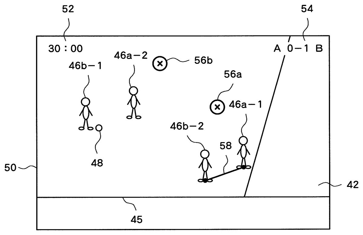
FIG. 5shows one example of a game screen image50. As shown inFIG. 5, an image showing a picture obtained by viewing the virtual three dimensional space40from the virtual camera49is shown as a game screen image50. The game screen image50includes a time indication52showing a period of time elapsed and a score indication54showing a score. Further, a cursor56aindicating the position designated by the controller22of the first user and a cursor56bindicating the position designated by the controller22of the second user are also shown in the game screen image50. Note that although the cursors56a,56bare round in this embodiment, the cursors56a,56bmay have any other shape. Note that inFIG. 5, the player objects46a-1,46a-2are player objects46belonging to the first teams, and the player objects46b-1,46b-2are player objects46belonging to the second team.
Basically, the respective player objects46move according to a predetermined algorithm, though a user can designate a movement destination position and a kick destination position for a player object46belonging to the user team.
A method for designating a movement destination position and a kick destination position for a player object46will be described. Here, assume a case in which a second user gives a designation instruction to the player object46b-1. In this case, initially, the second user selects the player object46b-1. Specifically, the second user directs the front end portion22aof the controller22to the player object46b-1to thereby move the cursor56bto the player object46b-1, and presses a selection button (e.g., the button37b). Thereupon, the player object46b-1is selected as a target to which a designation instruction is given (an instruction target).
With the player object46b-1selected as an instruction target, the second user can designate a movement destination position for the player object46b-1by directing the front end portion22aof the controller22in a direction towards this destination position. That is, the position of the cursor56b(a position in the virtual three dimensional space40, corresponding to the display position of the cursor56b) is set as the movement destination position for the player object46b-1, upon which the player object46b-1begins moving toward the movement destination position.
Further, when the player object46b-1holds the ball object48and is selected as an instruction target, the second user can designate a kick direction for the player object46b-1by directing the front end portion22aof the controller22in the intended kicking direction. That is, in response to a kick instruction button (e.g., the button37a) being pressed by the user, the position of the cursor56b(a position in the virtual three dimensional space40, corresponding to the display position of the cursor56b) is set as a kick destination position, and the player object46b-1kicks the ball object48toward the kick destination position. For example, when the second user presses the kick instruction button with the cursor56bhaving been moved to and placed on the player object46b-2in the game screen image50shown inFIG. 5, the player object46b-1makes a pass to the player object46b-2.
The above described soccer game has a marking instruction function. A marking instruction function is a function which enables a user to instruct a player object46of the user team to mark a player object46of the opponent team. Note that “to mark” means to defend against a specific opponent player while keeping close to that player (while keeping the distance to the specific opponent player shorter than a predetermined distance).
Here, assume a case in which the first user instructs to mark the player object46b-2in the situation shown inFIG. 5. In this case, initially, the first user selects the player object46b-2. Specifically, the first user directs the front end portion22aof the controller22to the player object46b-2to thereby move the cursor56aso as to be placed on the player object46b-2, and presses the selection button (e.g., the button37b). Thereupon, the player object46b-2is selected as a target to be marked (marking target). With the player object46b-2selected as a marking target, a player object46located closest to the player object46b-2, among the player objects46belonging to the first team, is selected as a marker who marks the player object46b-2. For example, in the situation shown inFIG. 5, the player object46a-1is selected as a marker. In this case, the player object46b-2and the player object46a-1are caused to be correlated to each other, and the player object46a-1begins marking the player object46b-2.FIG. 6shows a game screen image50to be shown in the above. In this case, a line image58connecting the player object46a-1and the player object46b-2is shown. By referring to the line image58, the user can know that the player object46b-2and the player object46a-1are correlated to each other.
Alternatively, marking a player object46of the opponent team may be instructed as follows. Here again assume a case in which the first user instructs to mark the player object46b-2in the situation shown inFIG. 5. In this case, the first user initially places the cursor56aon any player object46(a player object46a-1, here) among the player objects46belonging to the first team, and then moves the cursor56ato be placed on the player object46b-2, while pressing the selection button (e.g., the button37b), and then releases the pressed selection button. Thereupon, the player object46b-2and the player object46a-1are caused to be correlated to each other, and the player object46a-1begins marking the player object46b-2. As described above, an arrangement for enabling a user to select both of the marker and the marking target may be applied.
Note that a player object46which marks a player object46of the opponent team will be hereinafter referred to as a “marker player object”, and that a player object46to be marked by a marker player object will be hereinafter referred to as a “marking target player object”. Moreover, a player object46which holds the ball object48will be hereinafter referred to as a “ball holding player object”.
A marker player object acts in a “normal mode” or an “intercept mode”.FIGS. 7 and 8are diagrams explaining the “normal mode” and the “intercept mode”. In these diagrams, the position (B) indicates the position of a ball holding player object (or the ball object48); the position (T) indicates the position of a marking target player object; the position (M) indicates the position of a marker player object; and the position (G) indicates a representative point of the goal object44of the team to which the marker player object belongs.
The “normal mode” is a mode in which a marker player object tries to prevent a marking target player object from receiving a pass from a ball holding player object and pushing toward the goal object44. As shown inFIG. 7, in the “normal mode”, the position (M) of the marker player object is controlled so as to be located on the straight line60connecting the representative point (G) of the goal object44of the team to which the marker player object belongs and the position (T) of the marking target player object.
The “intercept mode” is a mode in which a marker player object tries to intercept a pass from a ball holding player object to a marking target player object. As shown inFIG. 8, in the “intercept mode”, the position (M) of the marker player object is controlled so as to be located on the straight line62connecting the position (T) of the marking target player object and the position (B) of the ball holding player object.
Note that both in the “normal mode” and the “intercept mode”, when a marking target player object holds the ball object48, a marker player object tries to deprive the marking target player object of the ball object48according to a predetermined algorithm.
A user can switch the action mode (hereinafter referred to as a “marker action mode”) of a marker player object belonging to the user team by, e.g., pressing a switching instruction button (e.g., the button31).
For example, in the situation shown inFIG. 5, the first user needs to defend against the player object46b-2which is highly likely to receive a pass from the player object46b-1, while defending against the player object46b-1holding the ball object48. Specifically, the first user needs to carry out a game operation, while defending against the player object46b-2by trying to prevent the player object46b-2from receiving a pass from the player object46b-1and pushing toward the goal object44, so as to intercept a pass from the player object46b-1to the player object46b-2. Without a marking instruction function, the first user would need to defend against the player object46b-1and the player object46b-2while switching the instruction target between the player object46a-1and the player object46a-2. Such an operation, however, may be difficult to achieve for some users (in particular, a user at a low training level).
Regarding this point, using the marking instruction function, a user can instruct a player object46of the user team to mark the player object46b-2by pressing the selection button while holding the controller22such that the front end portion22athereof is directed to the player object46b-2. In addition, the user can instruct, by pressing the switching instruction button, a player object46(player object46a-1) marking the player object46b-2to either try (A) to prevent the player object46b-2from receiving a pass from the player object46b-1and pushing toward the goal object44or (B) to intercept a pass from the player object46b-1to the player object46b-2. That is, using the marking instruction function, the first user can instruct, through a relatively simple operation, to defend against the player object46b-2which is highly likely to receive a pass from the player object46b-1. As a result, the first user, while defending against the player object46b-1holding the ball object48by operating the player object46a-2, can instruct the player object46a-1to defend against the player object46b-2which is highly likely to receive a pass from the player object46b-1by pressing the switching instruction button. That is, the marking instruction function can enhance operability for a user when a player object46of the opponent team holds the ball object48. In the following, a structure for realizing the marking instruction function will be described.
FIG. 9is a functional block diagram mainly showing a function according to the present invention among those realized in the game device10. As shown inFIG. 9, the game device10comprises a game situation data storage unit70(player character state storage means), a game situation data update unit72, and a display control unit74. These functional blocks are realized by the microprocessor13by executing a program.
The game situation data storage unit70is realized using, for example, the main memory14. Game situation data describes the current situation of a game and is stored in the game situation data storage unit70.FIG. 10shows one example of game situation data. Game situation data includes match time data and score data. The game situation data includes position data of the cursor56aof the first user and position data of the cursor56bof the second user. Cursor position data is data describing, for example, the display position of a cursor or a position in the virtual three dimensional space40, corresponding to the display position of a cursor. The game situation data includes the state data of the virtual camera49and the state data of the ball object48. The state data of the virtual camera49includes position data, posture (viewing direction) data, and so forth. The state data of the ball object48includes position data, movement direction and speed data, and so forth. The game situation data includes state data of each of the player objects46belonging to the first and second teams, respectively. The state data of the player object46includes position data, posture data, movement direction and speed data, an instruction target flag, a ball holding flag, a marker flag, a marking target player ID, a marker action mode flag, and the like. An “instruction target flag” is data indicating whether or not a player object46is being selected as an instruction target. A “ball holding flag” is data indicating whether or not a player object46is holding the ball object48. A “marker flag” is data indicating whether or not a player object46is a marker player object. A “marking target player ID” is data indicating the ID (identification information) of a player object46which the player object46is marking. A “marker action mode flag” is data describing the current marker action mode of a player object46. The marker action mode of each player object46is set to the “normal mode” at the beginning of a match. Note that, inFIG. 10, “player object (A01)”, “player object (A02)”, and “player object (A11)” are player objects46of the first team, while “player object (B01)” and “player object (B11)” are player objects46of the second team.
The game situation data update unit72is realized mainly using the microprocessor13, for example. The game situation data update unit72updates the game situation data stored in the game situation data storage unit70. The game situation data update unit72comprises, as a structure related to the marking instruction function, a marking target selection unit72a, a marker selection unit72b, a marker control unit72c, a switching condition determination unit72f, and a marker control switching unit72g.
The marking target selection unit72aselects a marking target player object from among the player objects46belonging to the opponent team. The marker selection unit72bselects a marker player object from among the player objects46belonging to the user team.
In this embodiment, the marking target selection unit72aselects a marking target player object from among the player objects46belonging to the opponent team according to a selection operation carried out by a user. That is, the marking target selection unit72areceives user selection of a marking target player object. After selection of a marking target player object, the marker selection unit72bselects a marker player object from among the player objects46belonging to the team operated by the user, based on the position of the marking target player object and the positions of the respective player objects46belonging to the user team. For example, the marker selection unit72bmay select, as a marker player object, a player object46located closest to the position of the marking target player object from among the player objects46belonging to the user team.
Note that alternatively, the marker selection unit72bmay select a marker player object from among the player objects46belonging to the user team according to a selection operation carried out by a user. In this case, after selection of a marker player object, the marking target selection unit72amay select a marking target player object from among the player objects46belonging to the opponent team, based on the position of the marker player object and the positions of the respective player objects46belonging to the opponent team. For example, the marking target selection unit72amay select, as a marking target player object, a player object46located closest to the position of the marker player object from among the player objects46belonging to the opponent team.
[Marker Control Unit]
The marker control unit72ccontrols a marker player object. The marker control unit72ccomprises a first marker control unit72dand a second marker control unit72e.
The first marker control unit72dcorresponds to the “normal mode”. An operation of the first marker control unit72dwill be described referring toFIG. 7. The first marker control unit72dcontrols the position (M) of the marker player object, based on the position (T) of the marking target player object and the representative point (G) of the goal object44of the team to which the marker player object belongs. In this embodiment, the first marker control unit72dcontrols the movement of the marker player object such that the position (M) of the marker player object is located on the straight line60connecting the position (T) of the marking target player object and the representative point (G) of the goal object44of the team to which the marker player object belongs.
Meanwhile, the second marker control unit72ecorresponds to the “intercept mode”. An operation of the second marker control unit72ewill be described referring toFIG. 8. The second marker control unit72econtrols the position (M) of the marker player object, based on the position (T) of the marking target player object and the position (B) of the ball holding player object (or the ball object48). In this embodiment, the second marker control unit72econtrols the movement of the marker player object such that the position (M) of the marker player object is located on the straight line62connecting the position (T) of the marking target player object and the position (B) of the ball holding player object.
The switching condition determination unit72fdetermines whether or not a predetermined switching condition is satisfied. For example, the switching condition includes a condition for determining whether or not a predetermined switching instruction operation (e.g., pressing a switching instruction button) is carried out.
The marker control switching unit72gswitches between a state in which the first marker control unit72dcontrols the movement of a marker player object and a state in which the second marker control unit72econtrols the movement of a marker player object. The marker control switching unit72geffects the switching based on the result of determination by the switching condition determination unit72f. In this embodiment, the marker control switching unit72geffects the above described switching when a predetermined switching instruction operation is carried out.
The display control unit74is realized mainly using, for example, the microprocessor13and the image processing unit15. The display control unit74renders a game screen image50into a VRAM, based on the game situation data stored in the game situation data storage unit70. The game screen image50rendered in the VRAM is output at a predetermined time to be displayed on the monitor30.
In the following, a process to be carried out by the game device10to realize the above-described function blocks will be described.FIG. 11is a flowchart of a process to be carried out by the game device10every predetermined period of time (e.g., 1/60thof a second). The microprocessor13carries out the process shown inFIG. 11according to a program stored in the optical disk32.
As shown inFIG. 11, the microprocessor13(game situation data update unit72) updates the position data of the cursors56a,56band the state data of the respective player objects46(S101).FIGS. 12 and 13are flowcharts of a process to be carried out in this step.
In the process shown inFIGS. 12 and 13, based on an operating signal (pointing information) supplied from the controller22of a user, initially, the microprocessor13updates the position data of the cursor corresponding to the user (S201). For example, the position data of the cursor56ais updated, based on an operating signal supplied from the controller22of the first user. This is similarly applied to the second user.
Further, based on the operating signal supplied from the controller22of the user, the microprocessor13(marking target selection unit72a) determines whether or not the user has selected a marking target player object (S202). For example, whether or not the first user has pressed the selection button is determined. With determination that the first user has pressed the selection button, it is then determined whether or not the front end portion22aof the controller22of the first user is directed to any of the player objects46belonging to the opponent team (second team). When the front end portion22aof the controller22of the first user is directed to any of the player objects46belonging to the opponent team, it is determined that the player object46is selected as a marking target player object. This is similarly applied to the second user.
When it is determined that the user has selected a marking target player object, the microprocessor13(marker selection unit72b) then selects a marker player object for the marking target player object (S203). For example, with a marking target player object having been selected by the first user, a player object46located closest to the position of the marking target player object, among the player objects46belonging to the first team, is selected as a marker player object. In this case, the microprocessor13updates the marker flag and the marking target player ID of the player object46selected as the marker player object (S204). In the above, the marking target player ID is updated to the ID of the player object46selected by the user as a marking target player object.
Note that although not shown inFIG. 12, the microprocessor13also determines whether or not the user has selected any player object46as an instruction target, and based on the determination result, updates the instruction target flags of the respective player objects46belonging to the user team.
After the process at S202to S204, the microprocessor13(switching condition determination unit72f) determines whether or not the user has pressed the switching instruction button (S205). With determination that the user has pressed the switching instruction button, the microprocessor13(marker control switching unit72g) updates the marker action mode flags of all of the player objects46belonging to the user team, and switches the marker action modes of all of the player objects46belonging to the user team from the “normal mode” to the “intercept mode”, or vice versa (S206).
After the process at S205and S206, the microprocessor13selects any of the player objects46as an update target object (S207), and carries out an update process (S208to S217) of the state data of the update target object. Initially, the microprocessor13reads the instruction target flag of the update target object from the game situation data, and determines whether or not the update target object is currently selected as an instruction target for a user (S208).
When the update target object is currently selected as an instruction target for a user, the microprocessor13updates the state data of the update target object, based on an operating signal supplied from the controller22of the user (S209). For example, the state data of the update target object is updated such that the update target object moves toward the position in the virtual three dimensional space40, corresponding to the display position of the cursor of the user. Also, for example, whether or not the kick instruction button has been pressed is determined based on an operating signal supplied from the controller22. When it is determined that the kick instruction button has been pressed, the state data of the update target object is updated such that the update target object carries out a kick action.
Meanwhile, when the update target object is not selected as an instruction target for the user, the microprocessor13reads the marker flag of the update target object from the game situation data to determine whether or not the update target object is a marker player object (S210). When the update target object is not a marker player object, the microprocessor13updates the state data of the update target object according to a predetermined algorithm (S213).
Meanwhile, when the update target object is a marker player object, the microprocessor13determines whether or not any player object46of the opponent team holds the ball object48(S211). When any player object46of the opponent team holds the ball object48, the microprocessor13reads the marking target player ID of the update target object from the game situation data to specify a player object46(marking target player object) to be marked by the update target object. Then, the microprocessor13determines whether or not the marking target player object holds the ball object48(S212). When the marking target player object holds the ball object48, the microprocessor13updates the state data of the update target object according to a predetermined algorithm (S213). For example, the state data of the update target object is updated such that the update target object acts so as to deprive the ball object48from the marking target player object.
Meanwhile, when the marking target player object does not hold the ball object48, the microprocessor13reads the marker action mode flag of the update target object from the game situation data to determine whether or not the marker action mode of the update target object is the “normal mode” (S214).
When the marker action mode of the update target object is the “normal mode”, the microprocessor13(first marker control unit72d) determines the movement destination position for the update target object, based on the position (T) of the player object46(marking target player object) marked by the update target object and the representative point (G) of the goal object44of the team to which the update target object belongs (S215: seeFIG. 7). For example, a position on the straight line60from the position (T) of the marking target player object to the representative point (G) of the goal object44with the distance from the position (T) of the marking target player object being a predetermined distance is determined as the movement destination position.
Meanwhile, when the marker action mode of the update target object is not the “normal mode” but the “intercept mode”, the microprocessor13(second marker control unit72e) determines the movement destination position for the update target object, based on the position (T) of the player object46(marking target player object) marked by the update target object and the position (B) of the ball holding player object (B) (S216: seeFIG. 8). For example, a position on the straight line62from the position (T) of the marking target player object to the position (B) of the ball holding player object with the distance from the position (T) of the marking target player object being a predetermined distance is determined as the movement destination position.
Note that when it is determined at S211that no player object46of the opponent team is holding the ball object48, the microprocessor13determines the movement destination position for the update target object in a manner similar to that in the case where the marker action mode of the update target object is the “normal mode” (S215).
With the movement destination position for the update target object determined at S215or S216, the microprocessor13(first marker control unit72dand second marker control unit72e) updates the state data of the update target object, based on the movement destination position for the update target object (S217). That is, the state data of the update target object is updated such that the update target object moves toward the movement destination position.
After the process at S208to S217, the microprocessor13determines whether or not there is any player object46for which a state data update process (S208to S217) has not yet been carried out (S218). When there is any such player object46, any of such player objects46is selected as a new update target object (S219), and a state data update process (S208to S217) is carried out relative to the update target object. Meanwhile, when there is no such player object46, this process is terminated.
Note that although not shown inFIGS. 12 and 13, when a predetermined release operation is carried out, the marker flag and the marking target player ID of a marker player object belonging to the team of a user having carried out the release operation are reset. That is, the player object46which is the marker player object no longer marks the player object46of the opponent team.
As shown inFIG. 11, after the position data of the cursors56a,56band the state data of the respective player objects46are updated, the microprocessor13(game situation data update unit72) updates the state data of the ball object48(S102). For example, the position of the ball object48is updated to a position displaced from the current position in the movement direction by a distance in accordance with the moving speed. Also, for example, when any player object46kicks the ball object48, the state data of the ball object48is updated such that the ball object48moves in the kick direction.
Thereafter, the microprocessor13(game situation data update unit72) updates the state data of the virtual camera49(S103). For example, the state data of the virtual camera49is updated based on the position of the ball object48, and the like. In addition, the microprocessor13(game situation data update unit72) updates the match time data and the score data (S104). For example, when the ball object48has moved into the goal object44of one team, a score event occurs to the other team so that the score of the other team is increased.
Thereafter, the microprocessor13and the image processing unit15(display control unit74) update the game screen image50, based on the game situation data (S105). Initially, an image showing a picture obtained by viewing the virtual three dimensional space40from the virtual camera49is rendered into the VRAM. Thereafter, the time indication52and the score indication54are written into the respective predetermined positions in the image rendered in the VRAM. Further, the cursors56aand56bare written on the image rendered in the VRAM. The image having been rendered in the VRAM as described above is output as a game screen image50to be displayed on the monitor30.
The above described game device10has a marking instruction function. The marking instruction function enables a user, when, for example, a player object46of the opponent team holds the ball object48, to cause a player object46of the user team to mark a player object46which is highly likely to receive a pass from that player object46. Further, a user, by pressing the switching instruction button, can instruct a marker player object to either try (A) to prevent a marking target player object from receiving a pass from a ball holding player object and pushing toward the goal object44or (B) to intercept a pass from a ball holding player object to a marking target player object. That is, using the marking instruction function, a user, through a relatively simple operation, can defend against a player object46which is highly likely to receive a pass from a ball holding player object. As a result, a user, defending against a ball holding player object by operating a player object46located close to the ball holding player object, can instruct a player object of the user team to defend against a player object46which is highly likely to receive a pass from the ball holding player object by pressing the switching instruction button. That is, the game device10(marking instruction function) can enhance operability for a user when a player object46of the opponent team holds the ball object48.
Note that the present invention is not limited to the above-described above embodiment.
For example, the switching condition to be determined by the switching condition determination unit72fmay include a condition concerning a representative direction of a ball holding player object and the direction from the ball holding player object (or the ball object48) to a marking target player object. The switching condition may also include a condition for determining whether or not any other player object46(hereinafter referred to as a “teammate player object”) belonging to the team to which a marker player object belongs is located within an area specified based on the position of the marking target player object and the position of the goal object44of the team to which the marker player object belongs.FIG. 14is a flowchart of a process to be carried out in the game device10in the above described case;FIGS. 15 and 16are diagrams explaining the content of the process. The process shown inFIG. 14is carried out instead of the process at S206inFIG. 12.
When it is determined at S205inFIG. 12that the user has pressed the switching button, the microprocessor13, in the process shown inFIG. 14, selects any of the player objects46belonging to the user team as an update target object (S301), and carries out an update process (S302to S307) of the marker action mode (marker action mode flag) of the update target object. Specifically, the microprocessor13determines whether or not the update target object is a marker player object (S302). When the update target object is a marker player object, the microprocessor13determines whether or not any player object46belonging to the opponent team holds the ball object48(S303). When no player object46belonging to the opponent team holds the ball object48, the microprocessor13updates the marker action mode flag of the update target object to set the marker action mode of the update target object to the “normal mode” (S307).
Meanwhile, when any player objects46belonging to the opponent team holds the ball object48, the microprocessor13reads the marking target player ID of the update target object from the game situation data to specify the player object46(marking target player object) to be marked by the update target object. Then, the microprocessor13(switching condition determination unit72f) determines whether or not the angle (θ) between the representative direction80of the ball holding player object and the direction82from the position (B) of the ball holding player object to the position (T) of the marking target player object is equal to or smaller than a predetermined reference angle (θa), as shown inFIG. 15(S304). For example, whether or not an inner product of a vector indicating the representative direction80of the ball holding player object and a vector indicating the direction82from the position (B) of the ball holding player object to the position (T) of the marking target player object is within a predetermined value range is determined. Note that the representative direction80of the ball holding player object is a viewing direction or the forward direction of the face or body of the ball holding player object, which is specified based on the posture data of the ball holding player object.
When the above described angle (θ) is not equal to or smaller than the reference angle (θa), the microprocessor13(marker control switching unit72g) sets the marker action mode of the update target object to the “normal mode” (S307). Meanwhile, when the above described angle (θ) is equal to or smaller than the reference angle (θa), the microprocessor13(switching condition determination unit72f) determines whether or not a teammate player object (except the goal keeper) of the update target object is located in the vicinity of the straight line60from the position (T) of the marking target player object (a player object46marked by the update target object) to the representative point (G) of the goal object44of the team to which the update target object belongs (S305). For example, for each of the teammate player objects (except the goal keeper) of the update target object, whether or not the length (L) of a normal from the position (F) of the teammate player object to the straight line60is equal to or shorter than a predetermined reference distance (La) is determined. That is, whether or not any teammate player object (except the goal keeper) of the update target object is located in an area84within a distance from the straight line60, equal to or shorter than the predetermined reference distance (La) is determined. When it is determined that the length (L) of the normal from the position (F) of any teammate player object to the straight line60is equal to or shorter than the predetermined reference distance (La), it is determined that the teammate player object of the update target object is located in the vicinity of the straight line60.
When no teammate player object of the update target object is located in the vicinity of the above described straight line60, the microprocessor13(marker control switching unit72g) sets the marker action mode of the update target object to the “normal mode” (S307). Meanwhile, when any teammate player object of the update target object is located in the vicinity of the straight line60, the microprocessor13(marker control switching unit72g) updates the marker action mode flag of the update target object to set the marker action mode of the update target object to the “intercept mode” (S306).
After the process at S306or S307, the microprocessor13determines whether or not there is any player object46, among the player objects46belonging to the team of a user having pressed the switching instruction button, for which a marker action mode update process (S302to S307) has not yet been carried out (S308). When there is such a player object46, the microprocessor13selects any of such player objects46as a new update target object (S309), and carries out the marker action mode update process (S302to S307) relative to the update target object. Meanwhile, when there is no such player object46, the process at S207inFIG. 12is carried out.
A case in which it is determined at S304inFIG. 14that the angle (θ) is equal to or smaller than the reference angle (θa) refers to a case in which the ball holding player object is directed to a marking target player object and highly likely to make a pass to the marking target player object. This is considered a case appropriate for setting the action mode of the marker player object to the “intercept mode”. According to the process shown inFIG. 14, only when the ball holding player object is highly likely to make a pass to the marking target player object, the action mode of the marker player object is switched from the “normal mode” to the “intercept mode”. That is, in a case where a ball holding player object is unlikely to make a pass to the marking target player object, switching of the action mode of the marker player object from the “normal mode” to the “intercept mode” is restricted.
Note that at S304inFIG. 14the microprocessor13may determine whether or not a predetermined condition concerning the position of the cursor of a user operating the ball holding player object and the position of the marking target player object is satisfied.FIG. 17is a diagram explaining one example of the predetermined condition. For example, as shown inFIG. 17, the microprocessor13may determine whether or not the angle (θ) between the direction86from the position (B) of the ball holding player object (or the ball object48) to the position (C) of the cursor of a user operating the ball holding player object and the direction82from the position (B) of the ball holding player object to the position (T) of the marking target player object is equal to or smaller than a predetermined reference angle (6b). In the above, the position (C) of the cursor is a position in the virtual three dimensional space, corresponding to the display position of the cursor. Alternatively, the microprocessor13may determine whether or not the distance between the position (C) of the cursor of a user operating the ball holding player object and the position (T) of the marking target player object is equal to or shorter than a predetermined reference distance. Also in the above, only when the ball holding player object is highly likely to make a pass to the marking target player object, the action mode of the marker player object is switched from the “normal mode” to the “intercept mode”.
A case in which it is determined at S305inFIG. 14that the position (F) of a teammate player object of the update target object is located in the vicinity of the straight line60from the position (T) of the marking target player object to the representative point (G) of the goal object44of the team to which the update target object belongs refers to a case in which a teammate player object of the marker player object can defend against the marking target player object about to move toward the goal object44. That is, that is a case in which it is ensured that the marking target player object cannot move freely even if a through-pass from the ball holding player object to the marking target player object is successfully made. This situation is considered appropriate for setting the action mode of the marker player object to the “intercept mode”. Through the process shown inFIG. 14, only when a teammate player object of a marker player object can defend against a marking target player object about to move toward the goal object44, switching of the action mode of the marker player object from the “normal mode” to the “intercept mode” is effected. That is, in the case where a teammate player object of a marker player object cannot defend against a marking target player object about to move toward the goal object44, switching of the action mode of the marker player object from the “normal mode” to the “intercept mode” is restricted.
Note that the position of a marker player object may be used in S305inFIG. 14instead of the position of a marking target player object. That is, the microprocessor13may determine whether or not a teammate player object of the update target object is located in the vicinity of the straight line from the position (M) of the update target object (marker player object) to the representative point (G) of the goal object44of the team to which the update target object belongs. In the above as well, only when a teammate player object of a marker player object can defend against a marking target player object about to move toward the goal object44, switching of the action mode of the marker player object from the “normal mode” to the “intercept mode” is effected.
In the process shown inFIGS. 12 and 13, in response to the switching instruction button being pressed by a user, the action modes of all of the marker player objects belonging to the user team are switched from the “normal mode” to the “intercept mode” or vice versa. On the contrary, in the process shown inFIG. 14, for example, only in a case appropriate for setting the action mode of a marker player object to the “intercept mode”, switching of the action mode from the “normal mode” to the “intercept mode” is effected, and in a case not appropriate for setting the action mode of a marker player object to the “intercept mode”, switching from the “normal mode” to the “intercept mode” is restricted.
Note that the process at S205inFIG. 12may be omitted so that the process at S301inFIG. 14may be carried out after the process at S204inFIG. 12. With the above, the action mode of a marker player object is switched from the “normal mode” to the “intercept mode” without a user pressing the switching instruction button, when it is appropriate for setting the action mode of a marker player object to the “intercept mode”. As a result, the user can concentrate on defense against a ball holding player object, so that operability for a user when a player object46belonging to the opponent team holds the ball object48can be improved.
Also, e.g., at a time considered appropriate for switching the marker action mode, an image (e.g., an icon image) for informing a user of the arrival of such a time may be shown in the game screen image50.
For example, at a time with the angle (θ) between the representative direction80of the ball holding player object and the direction82from the position (B) of the ball holding player object to the position (T) of the marking target player object being equal to or smaller than the predetermined reference angle (6a), as shown inFIG. 15, a predetermined icon image may be shown in the game screen image50.
Also, for example, as shown inFIG. 17, at a time when the angle (θ) between the direction86from the position (B) of the ball holding player object (or the ball object48) to the position (C) of the cursor of a user operating the ball holding player object and the direction82from the position (B) of the ball holding player object (or the ball object48) to the position (T) of the marking target player object is equal to or smaller than a predetermined reference angle (θb), a predetermined icon image may be shown in the game screen image50.
Also, for example, at a time when the distance from the position (C) of the cursor of a user operating the ball holding player object to the position (T) of the marking target player object is equal to or shorter than a predetermined reference distance, a predetermined icon image may be shown in the game screen image50.
Also, for example, at a time when the position (F) of a teammate player object (except the goal keeper) of a marker player object is located in an area (for example, the area84shown inFIG. 16) specified based on the position (T) of a marking target player object and the representative point (G) of the goal object44of the team to which the marker player object belongs, a predetermined icon image may be shown in the game screen image50. Also, for example, at a time when the position (F) of a teammate player object (except the goal keeper) of a marker player object is located in an area specified based on the position (M) of the marker player object and the representative point (G) of the goal object44of the team to which the marker player object belongs, a predetermined icon image may be shown in the game screen image50.
With the above, a user can recognize a time appropriate for switching the marker action mode. That is, a user can recognize a time at which to press the switching instruction button.
Also, for example, although it is described in the above that the first marker control unit72dcontrols the position of a marker player object, based on the position of a marking target player object and the representative point (predetermined position) of the goal object44of the team to which the marker player object belongs, the first marker control unit72dmay use another predetermined position, instead of the representative point of the goal object44of the team to which the marker player object belongs. For example, as a “predetermined position”, a position on the goal line43on the side with the goal object44of the team to which the marker player object belongs may be used. Alternatively, as a “predetermined position”, a representative point of or a position in the vicinity of the corner area47on the side with the goal object44of the team to which the marker player object belongs may be used. With the above, in the “normal mode”, a marker player object may try to prevent a marking target player object from moving to a position in the vicinity of the goal line43(corner area47) and making a cross pass.
Note that, in this case, a “predetermined position” may change based on the position of a marking target player object. For example, a candidate for a “predetermined position” may be stored so as to be correlated to a position condition concerning the position of a marking target player object, so that the first marker control unit72dmay control the position of a marker player object, based on the position of a marking target player object and a “predetermined position” corresponding to a position condition satisfied by the position of the marking target player object. For example, as a “predetermined position” corresponding to an area in the vicinity of the touch line45, a representative point of the corner area47related to the touch line45is set. Also, for example, as a “predetermined position” corresponding to an area other than an area in the vicinity of the touch line45, a representative point of the goal object44is set. As described above, when a marking target player object is located in the vicinity of the touch line45in the “normal mode”, the marker player object may try to prevent the marking target player object from moving to a position in the vicinity of the corner area47and making a cross pass. Meanwhile, when a marking target player object is not located in the vicinity of the touch line45, the marker player object may try to prevent the marking target player object from receiving a pass from a ball holding player object and pushing toward the goal object44.
Also, for example, a game to be carried out in the game device10is not limited to a game in which a three dimensional game space formed using three coordinate elements is displayed as a game screen image50. A game to be carried out in the game device10may be a game in which a two dimensional game space formed using two coordinate elements is displayed in a game screen image50. That is, a game to be carried out in the game device10may be a game in which the positions, and the like, of a ball character and a player character are managed using two coordinate elements.
Also, for example, the opponent team may be operated by the microprocessor13. Also, for example, a game to be carried out in the game device10may be a game to be played by two or more users. Also, for example, a game to be carried out in the game device10is not limited to a soccer game. A game to be carried out in the game device10may be a sport game other than a soccer game. For example, the present invention can be applied to a sport game to be played using a moving object, such as a ball, a puck, or the like.
Also, for example, the operation input unit21may be a touch panel, a mouse, or the like.
Also, for example, the cursors56a,56bmay move according to an operation of the direction button36. Also, for example, the movement direction and kick direction of an instruction target player object46may be directly designated by a user by operating the direction button36. In this case, displaying of the cursors56a,56bcan be omitted.
Also, for example, objects representative of the cursors56aand56bmay be placed in the virtual three dimensional space40so that the cursors56aand56bare shown in the game screen image50.
Also, for example, although a program is supplied via the optical disk32, or an information storage medium, to the game device10in the above description, a program may be distributed through a communication network to the game device10.FIG. 18is a diagram showing a complete structure of a program distribution system using a communication network. A program distribution method according to the present invention will be described based onFIG. 18. As shown inFIG. 18, the program distribution system100comprises a game device10, a communication network106, and a program distribution device108. The communication network106includes, for example, the Internet and/or a cable television network. The program distribution device108comprises a game database102and a server104. In the system, a program similar to that which is stored in the optical disk32is stored in the game database (an information storage medium)102. When a demander requests game distribution, using the game device10, the request is sent through the communication network106to the server104. In response to the game distribution request, the server104reads the program from the game database102, and sends the read program to the game device10. Note that although game distribution is made in response to a game distribution request in the above, the server104may send a program one-sidedly. In addition, it is not always necessary to distribute all programs necessary to realize a game at the same time (collective distribution), and distribution of only a portion necessary depending on an aspect of a game may be applicable (dividing distribution). Game distribution through the communication network106, as described above, makes it easier for a demander to obtain a program.
Claims
- A game device for carrying out a sport game to be played by a user team and an opponent team, comprising: player character state storage means for storing positions of player characters belonging to the user team and positions of player characters belonging to the opponent team;marking target selection means for selecting a player character who is different from another player character who is holding a moving object among player characters belonging to the opponent team as a marking target player character;marker selection means for selecting any of the player characters belonging to the user team as a marker player character;first marker control means for controlling a position of the marker player character to be in a first mode, based on a position of the marking target player character and a predetermined position, such that the position of the marker player character is between the marking target player character and the predetermined position;second marker control means for controlling, in a case where a player character that is belonging to the opponent team and other than the marking target player holds the moving object, the position of the marker player character to be in a second mode, based on both the position of the marking target player character and a position of the moving object or a position of the player character holding the moving object among the player characters belonging to the opponent team such that the position of the marker player character is between the marking target player character and the position of the moving object or the position of the player character holding the moving object;determination means for determining whether or not a predetermined switching condition is satisfied;and marker control switching means for switching, in the case where the player character that is belonging to the opponent team and other than the marking target player holds the moving object, a state in which the first marker control means controls the position of the marker player character and a state in which the second marker control means controls the position of the marker player character, based on a result of determination by the determination means.
- The game device according to claim 1 , wherein the player character state storage means stores a representative direction of the player character belonging to the opponent team, the switching condition includes a condition for determining whether or not an angle between the representative direction of the player character holding the moving object among the player characters belonging to the opponent team and a direction from the position of the player character holding the moving object among the player characters belonging to the opponent team to the position of the marking target player character is equal to or smaller than a predetermined reference angle, and the marker control switching means includes a means for switching, in a case where the angle is equal to or smaller than the predetermined reference angle, from the state in which the first marker control means controls the position of the marker player character to the state in which the second marker control means controls the position of the marker player character.
- The game device according to claim 1 , wherein the opponent team is operated by an opponent user, the game device further comprises means for displaying a cursor which moves according to an operation by the opponent user in a game screen image, and means for, in a case where the opponent user carries out a predetermined pass instruction operation, causing the player character holding the moving object, among the player characters belonging to the opponent team, to make a pass toward a position of the cursor, and the switching condition includes a condition concerning the position of the cursor and the position of the marking target player character.
- The game device according to claim 3 , wherein the switching condition includes a condition for determining whether or not an angle between a direction from the position of the moving object or the position of the player character holding the moving object, among the player characters belonging to the opponent team, to the position of the cursor and a direction from the position of the moving object or the position of the player character holding the moving object, among the player characters belonging to the opponent team, to the position of the marking target player character is equal to or smaller than a predetermined reference angle, and the marker control switching means includes a means for, in a case where the angle is equal to or smaller than the predetermined reference angle, switching from the state in which the first marker control means controls the position of the marker player character to the state in which the second marker control means controls the position of the marker player character.
- The game device according to claim 3 , wherein the switching condition includes a condition for determining whether or not a distance between the position of the cursor and the position of the marking target player character is equal to or shorter than a predetermined reference distance, and the marker control switching means includes a means for, in a case where the distance is equal to or shorter than the predetermined reference distance, switching from the state in which the first marker control means controls the position of the marker player character to the state in which the second marker control means controls the position of the marker player character.
- The game device according to claim 1 , wherein the switching condition is a condition for determining whether or not a player character other than the marker player character, among the player characters belonging to the user team, is located within an area specified based on the position of the marking target player character and the predetermined position, and the marker control switching means includes means for, in a case where the player character other than the marker player character, among the player characters belonging to the user team, is located within the area, switching from the state in which the first marker control means controls the position of the marker player character to the state in which the second marker control means controls the position of the marker player character.
- The game device according to claim 1 , wherein the switching condition is a condition for determining whether or not a player character other than the marker player character, among the player characters belonging to the user team, is located within an area specified based on the position of the marker player character and the predetermined position, and the marker control switching means includes means for, in a case where the player character other than the marker player character, among the player characters belonging to the user team, is located within the area, switching from the state in which the first marker control means controls the position of the marker player character to the state in which the second marker control means controls the position of the marker player character.
- The game device according to claim 1 , wherein the determination means determines whether or not a predetermined switching instruction operation is carried out, the marker control switching means, in a case where the predetermined switching instruction operation is carried out, switches the state in which the first marker control means controls the position of the marker player character and the state in which the second marker control means controls the position of the marker player character, and the game device further comprises second determination means for determining whether or not a condition concerning at least one of the position of the marker player character and the position of the marking target player character is satisfied, and means for displaying a predetermined image in the game screen image, based on a result of determination by the second determination means.
- The game device of claim 1 , wherein the state in which the first marker control unit controls the position of the marker player character is a normal mode in which the marker player character tries to prevent the marking target player character from receiving a pass from the player character holding the moving object and pushing toward a goal object.
- The game device of claim 1 , wherein the state in which the second marker control unit controls the position of the marker player character is an intercept mode in which the marker player character tries to intercept a pass from the player character holding the moving object to the marking target player character.
- The game device of claim 1 , wherein the marking target player character is selected when the another player character is holding the moving object.
- The game device of claim 1 , wherein the marker control switching means switches between the first mode and the second mode based on an angle between a representative direction of the player character who is holding the moving object and a direction from the player character who is holding the moving object to the marking target player character.
- A game device control method for controlling a game device for carrying out a sport game to be played by a user team and an opponent team, the method comprising: reading content stored in player character state storage unit for storing positions of player characters belonging to the user team and positions of player characters belonging to the opponent team;selecting a player character who is different from another player character who is holding a moving object among the player characters belonging to the opponent team as a marking target player character;selecting any of the player characters belonging to the user team as a marker player character;a first marker control operation of controlling a position of the marker player character to be in a first mode, based on a position of the marking target player character and a predetermined position, such that the position of the marker player character is between the marking target player character and the predetermined position;a second marker control operation of controlling, in a case where a player character that is belonging to the opponent team and other than the marking target player holds the moving object, the position of the marker player character to be in a second mode, based on both the position of the marking target player character and a position of the moving object or a position of the player character holding the moving object, among the player characters belonging to the opponent team, such that the position of the marker player character is between the marking target player character and the position of the moving object or the position of the player character holding the moving object;determining, by a processor, whether or not a predetermined switching condition is satisfied;and switching, in the case where the player character that is belonging to the opponent team and other than the marking target player holds the moving object, a state in which the position of the marker player character is controlled at the first marker control operation and a state in which the position of the marker player character is controlled at the second marker control operation, based on a result of the determining whether or not the predetermined switching condition is satisfied.
- A non-transitory computer readable information storage medium storing a program for causing a computer to function as a game device for carrying out a sport game to be played by a user team and an opponent team, the program for causing the computer to function as: player character state storage means for storing positions of player characters belonging to the user team and positions of player characters belonging to the opponent team;marking target selection means for selecting a player character who is different from another player character who is holding a moving object among the player characters belonging to the opponent team as a marking target player character;marker selection means for selecting any of the player characters belonging to the user team as a marker player character;first marker control means for controlling a position of the marker player character to be in a first mode, based on a position of the marking target player character and a predetermined position, such that the position of the marker player character is between the marking target player character and the predetermined position;second marker control means for controlling, in a case where the player character that is belonging to the opponent team and other than the marking target player holds the moving object, the position of the marker player character to be in a second mode, based on both the position of the marking target player character and a position of the moving object or a position of the player character holding the moving object, among the player characters belonging to the opponent team, such that the position of the marker player character is between the marking target player character and the position of the moving object or the position of the player character holding the moving object;determination means for determining whether or not a predetermined switching condition is satisfied;and marker control switching means for switching, in the case where the player character that is belonging to the opponent team and other than the marking target player holds the moving object, a state in which the first marker control means controls the position of the marker player character and a state in which the second marker control means controls the position of the marker player character, based on a result of determination by the determination means.
- A game device for carrying out a sport game to be played by a user team and an opponent team, comprising: player character state storage unit which stores positions of player characters belonging to the user team and positions of player characters belonging to the opponent team;marking target selection unit configured to select any of the player characters belonging to the opponent team as a marking target player character;marker selection unit configured to select a player character who is different from another player character who is holding a moving object among the player characters belonging to the user team as a marker player character;first marker control unit configured to control a position of the marker player character to be in a first mode, based on a position of the marking target player character and a predetermined position, such that the position of the marker player character is between the marking target player character and the predetermined position;second marker control unit configured to control, in a case where a player character that is belonging to the opponent team and other than the marking target player holds the moving object, the position of the marker player character to be in a second mode, based on both the position of the marking target player character and a position of the moving object or a position of the player character holding the moving object among the player characters belonging to the opponent team, such that the position of the marker player character is between the marking target player character and the position of the moving object or the position of the player character holding the moving object;determination unit, implemented by a processor, configured to determine whether or not a predetermined switching condition is satisfied;and marker control switching unit configured to switch, in the case where the player character that is belonging to the opponent team and other than the marking target player holds the moving object, a state in which the first marker control unit controls the position of the marker player character and a state in which the second marker control unit controls the position of the marker player character, based on a result of determination by the determination unit.
Disclaimer: Data collected from the USPTO and may be malformed, incomplete, and/or otherwise inaccurate.