U.S. Pat. No. 8,574,078
Game apparatus, communication apparatus, wireless game controller, and game system
AssigneeSony Corporation; Sony Computer Entertainment Inc.
Issue DateApril 23, 2007
Illustrative Figure
Abstract
A technology of realizing wireless communication between a parent station and child stations with efficiency. In a game system according to the present invention, a game apparatus sets the maximum number of times of transmission for wireless game controllers, in accordance with the number of wireless game controllers that are communicating at a predetermined communication cycle. Here, time for establishing connection with a new wireless game controller is reserved within each communication cycle, thereby allowing new users to join the game. The maximum number of times of transmission is re-set when the number of wireless game controllers connected changes.
Description
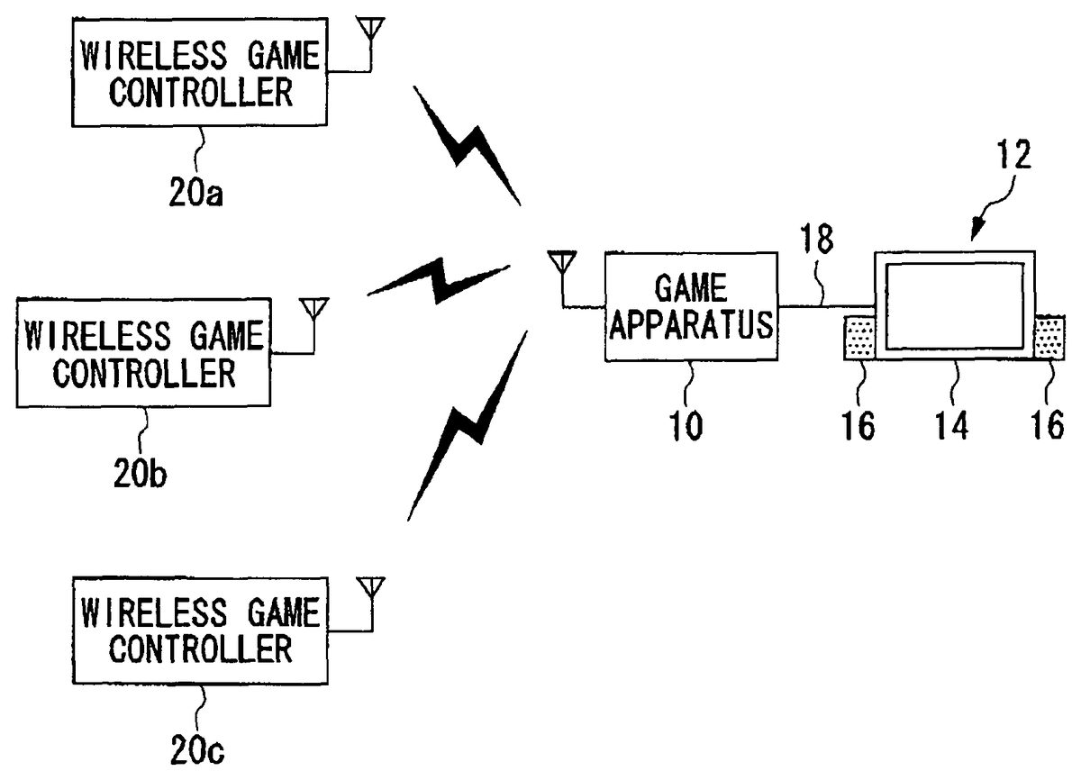
DETAILED DESCRIPTION OF THE INVENTION The invention will now be described by reference to the preferred embodiments. This does not intend to limit the scope of the present invention, but to exemplify the invention. FIG. 1shows the general configuration of a game system1according to an embodiment of the present invention. The game system1of the present embodiment includes a game apparatus10, an output apparatus12, and wireless game controllers20a,20b, and20c(hereinafter, referred to as “wireless game controllers20” or “wireless game controller20” if collectively dubbed). It should be noted that whileFIG. 1shows three wireless game controllers20, the number of wireless game controllers20is not intended to be limited to three. The wireless game controllers20are operation input devices for users to make operation inputs from. The game apparatus10is a processing unit which processes a game application based on the operation inputs from the wireless game controllers20, and generates image signals and sound signals that indicate the result of processing of the game application. It should be appreciated that the technology to be described in the present embodiment can also be practiced in entertainment systems that have processing units for executing other types of applications, not necessarily game applications. For a representative example of the entertainment system, description will hereinafter be given of the game system1which executes a game application. The output apparatus12includes an image display apparatus14and a sound output apparatus16. The image display apparatus14is a display for outputting image signals. It receives image signals generated by the game apparatus10through a cable18, and displays a game screen. The sound output apparatus16consists of speakers for outputting sound. It receives sound signals generated by the game apparatus10through the cable18, and outputs game sound. In the game system1shown inFIG. 1, the game apparatus10and the output apparatus12are wired with the cable18, whereas they may be connected wirelessly. For example, a home ...
DETAILED DESCRIPTION OF THE INVENTION
The invention will now be described by reference to the preferred embodiments. This does not intend to limit the scope of the present invention, but to exemplify the invention.
FIG. 1shows the general configuration of a game system1according to an embodiment of the present invention. The game system1of the present embodiment includes a game apparatus10, an output apparatus12, and wireless game controllers20a,20b, and20c(hereinafter, referred to as “wireless game controllers20” or “wireless game controller20” if collectively dubbed). It should be noted that whileFIG. 1shows three wireless game controllers20, the number of wireless game controllers20is not intended to be limited to three.
The wireless game controllers20are operation input devices for users to make operation inputs from. The game apparatus10is a processing unit which processes a game application based on the operation inputs from the wireless game controllers20, and generates image signals and sound signals that indicate the result of processing of the game application. It should be appreciated that the technology to be described in the present embodiment can also be practiced in entertainment systems that have processing units for executing other types of applications, not necessarily game applications. For a representative example of the entertainment system, description will hereinafter be given of the game system1which executes a game application.
The output apparatus12includes an image display apparatus14and a sound output apparatus16. The image display apparatus14is a display for outputting image signals. It receives image signals generated by the game apparatus10through a cable18, and displays a game screen. The sound output apparatus16consists of speakers for outputting sound. It receives sound signals generated by the game apparatus10through the cable18, and outputs game sound.
In the game system1shown inFIG. 1, the game apparatus10and the output apparatus12are wired with the cable18, whereas they may be connected wirelessly. For example, a home network using a wireless LAN may be constructed between the game apparatus10and the output apparatus12. When the game apparatus10and the output apparatus12are connected wirelessly, it is possible to locate the game apparatus10and the output apparatus12at desired sites. This allows users to freely play the game at different locations.
The wireless game controllers20are wireless communication terminals which transmit users' operation inputs to the game apparatus10by wireless means. The wireless game controllers20and the game apparatus10perform wireless communication with each other using Bluetooth™ protocols. The game apparatus10is capable of communicating wirelessly with a plurality of wireless controllers20. In other words, the game system1can realize one-to-N connection between the game apparatus10and the wireless game controllers20. The game apparatus10functions as a parent station or a master. The wireless game controller20functions as a child station or a slave.
The wireless game controllers20are powered by batteries, and each comprises a plurality of buttons and keys for making operation inputs for game progress. When a user operates the buttons and keys on the wireless game controller20, the operation input data are transmitted to the game apparatus10wirelessly. The game apparatus10receives the operation input data pertaining to the game application from the wireless game controllers20, controls the progress of the game in accordance with the operation input data, and generates game image signals and game sound signals. The game image signals and game sound signals are output to the image display apparatus14and the sound output apparatus16, respectively.
FIG. 2shows a Bluetooth state transition diagram. As shown in the diagram, the possible states of Bluetooth terminals are classified into a standby phase, a synchronization establishment phase, a communication connection phase, and low-power modes.
A slave enters a “standby” state immediately after it is powered on or when its communication link is disconnected. In the “standby” state, no data will be transmitted or received.
The synchronization establishment phase includes: a state where the master inquires about connection of surrounding slave(s), i.e., makes “inquiry”, and a state where the master identifies slave(s) and performs “paging”. In the “inquiry” state, the master broadcasts an IQ (inquiry) packet to adjacent terminal devices. The slave that receives the IQ packet returns an FHS (Frequency Hop Synchronization) packet including a Bluetooth address and clock information to the master. At this point of transmission and reception, a consensus as to a frequency hopping pattern is yet to be established between the master and the slave. A fixed hopping pattern dedicated and defined for inquiry is therefore used.
In the “page” state, the master receives FHS packets from the slaves, recognizes what kinds of slaves are present, and then transmits an ID packet to a certain slave. When a response to the ID packet is returned from the certain slave, the master transmits an FHS packet and notifies the slave of its clock and a slave identifier. The slave identifier is a 3-bit address (1to7) assigned to the slave, and referred to as AM_ADDR (Active Member ADDRess). This makes it possible for the master and the slave to share the same hopping pattern.
Performing “paging”, the slave and the master create a piconet therebetween and enter a “connection” state. A piconet refers to a network that is formed temporarily between Bluetooth terminals when they are brought close to each other. Up to eight Bluetooth terminals can join a single piconet. To maintain the synchronization of the piconet, the slave offsets its own clock by a difference from the master clock. In a single piconet, the master can function as a parent station to connect with a maximum of seven slaves. In the “connection” state, control packets for establishing a communication link are transmitted and received to enable data transfer in an “active mode”. In the active mode, the slave basically monitors signals transmitted from the master. Since the active slave must remain ready to transmit and receive packets all the time, power consumption of the active slave becomes highest. When a data transfer is completed to disconnect the communication link, the slave returns to the standby state.
In addition to the “active mode”, the modes where the communication link is established include a “park mode”, a “hold mode” and a “sniff mode”. The slave can shift from the “active mode” to the three types of low-power consumption modes, i.e., the “park mode”, “hold mode” and “sniff mode”. The master can also shift from the “active mode” to the “hold mode”.
In the “park mode”, the slave remains in synchronization with the piconet, i.e., in synchronization with the hopping pattern and the master clock. However, the slave cannot exchange packets with the master. The slave in this state receives data from the master at a predetermined communication cycle (beacon interval), and can immediately join the piconet when necessary. In the park mode, the slave identifier (AM_ADDR) assigned by the master, i.e., 3-bit address (1to7) given to the slave in connection, is once returned to the master. Thus, even if a slave attempts to rejoin the piconet, it cannot join immediately unless there is an unused slave identifier. The master, in the meantime, gives a 8-bit park slave identifier to a slave which enters the park mode. The master can manage up to 255 parked terminal devices, and can allow only required slaves to join the piconet at any time.
In the “hold mode”, the slave and the master do not perform transmission or reception for a certain set period of time (hold time) while remaining in synchronization with the piconet. They resume communication after the hold time.
In the “sniff mode”, the slave remains in synchronization with the piconet. In order for a slave to enter the sniff mode, the master and the slave negotiate to determine a sniff interval (SI) and a sniff offset. Packets can be transmitted and received only in a sniff slot which is composed of a plurality of time slots within the sniff interval. This allows the slave to suppress power consumption in the period other than the sniff slot. The sniff offset indicates the timing of the first time slot in the sniff slot.
The sniff slot is set by a sniff attempt (SA) parameter. The sniff attempt parameter NSAis used for determining the number of time slots in which the slave accepts packet transmission from the master. The slave monitors packets from the master during the period of the sniff slot which is specified by the sniff attempt parameter NSA. For example, if NSA=3, the slave monitors its packets and make a response for six time slots which are assigned in the sniff interval. In this case, six consecutive time slots in the sniff interval may be assigned to the sniff slot. Whether packets are addressed to itself or not is determined on the basis of the AM_ADDR included in the packet.
Since the wireless game controllers20are powered by batteries, it is preferable to reduce their power consumption as much as possible. The wireless game controllers20thus preferably run in the sniff mode. When there are a plurality of wireless game controllers20, each sniff interval is set in common. Sniff offsets are set so that the respective plurality of wireless game controllers20and the game apparatus10communicate with each other without temporal overlap. This can realize communications of time divisional multiplexing system.
In the game system1of the present embodiment, a wireless game controller20performs page processing while the game apparatus10is performing page scanning. The wireless game controller20thereby pages the game apparatus10and establishes connection in the active mode. At this time, the wireless game controller20functions as a master, and the game apparatus10a slave. The master and the slave then switch in function so that the game apparatus10serves as a master and the wireless game controller20a slave. In this state, the wireless game controller20requests the game apparatus10to connect in the sniff mode. Then, the game apparatus10notifies the wireless game controller20of necessary parameters, and establishes connection in the sniff mode.
Based on the sniff interval and the number of game controllers that are connected to form the piconet, the game apparatus10sets the maximum number of times of transmission available for each individual wireless game controller20to transmit operation input data. This maximum number of times of transmission is determined by the sniff attempt parameter NSA. For example, if NSA=3, the wireless game controllers20are able to transmit data up to three times each. In the present embodiment, “the maximum number of times of transmission” refers to the maximum number of chances of transmission given within a single communication interval (communication cycle).
Once a wireless game controller20successfully transmits data to the game apparatus10in its sniff slot, the game apparatus10will not transmit a further data transfer request to that wireless game controller20in the same sniff slot. It follows that the wireless game controller20will not perform data transmission in the rest of the sniff slot period. Suppose, for example, that a sniff slot consisting of six time slots (NSA=3) is set. In a favorable wireless environment, data transmission is performed successfully in the first two time slots. No data will thus be transmitted in the remaining four time slots. When the data transmission in the first two time slots fails, conversely, the remaining four time slots can be used for data retransmission processing. It should be noted that the “data retransmission processing” according to the present embodiment merely refers to the transmitting of some data in subsequent time slots within the sniff slot where data transmission has failed in the first two time slots. The data to be transmitted in the subsequent time slots need not necessarily be the same as the transmission-failed data in the first two time slots. Data transmission fails in the first two time slots when the wireless game controller20transmits erroneous data or when the data transmitted from the wireless game controller20cannot be received by the data apparatus10, or when the wireless game controller20cannot transmit the data itself. In the present embodiment, the game apparatus10determines the maximum number of times of transmission for the wireless game controllers20connected so that time within the communication cycle can be reserved for establishing connection with a new wireless game controller20other than the connected wireless game controllers20.
The piconet operation involves frequency hopping processing in which a new frequency is selected at every 625 μs. Each single time slot thus has a duration of 625 μs. In the game system1, the result of processing of the game application is reflected on the output of the image display apparatus14which has a rate of 60 frames per second (=16.7 ms). It is therefore desirable that the game apparatus10receive operation input data from the wireless game controllers20at cycles shorter than 16.7 ms. This setting makes it possible for the game apparatus10to reflect the users' operation input data on the outputs of the image display apparatus14and the sound output apparatus16.
For the foregoing reason, the game apparatus10sets the sniff interval at 11.25 ms. This sniff interval is equivalent to a period of 18 time slots (625 μs×18). When the game system1has a plurality of wireless game controllers20, the sniff interval is set to be common between the controllers. That is, every wireless game controller20performs wireless communication with the game apparatus10at the sniff interval of 11.25 ms. It should be appreciated that the sniff interval may have a duration other than 11.25 ms, up to 16.7 ms.
FIGS. 3A to 3Eshow the allocation of time slots according to the present embodiment.FIG. 3aschematically shows time slots where the sniff interval SI is set to 11.25 ms. Sniff intervals would normally be set between the game apparatus10and the respective wireless game controllers20separately, and used to control wireless communication of the respective wireless game controllers20.
In contrast, according to the present embodiment, the game apparatus10sets a sniff interval and a sniff attempt parameter NSAwhich are common among all the wireless game controllers20connected. The game apparatus10also sets individual sniff offsets so that sniff slots allocated for the respective wireless game controllers20do not overlap each other on the time axis. In this way, the game apparatus10manages the communicable periods of the wireless game controllers20connected in a centralized fashion for appropriate scheduling, thereby facilitating efficient use of the time slots. In the following description, the sniff interval will start at time slot0and end at time slot17as shown inFIG. 3A.
FIGS. 3B to 3Eshow sniff slots allocated for wireless game controllers20. The number of slots in a sniff slot is determined by the sniff attempt parameter NSA. The start timing of a sniff slot is determined by a sniff offset.
The numerals shown inFIGS. 3B to 3Eindicate the slave identifiers given to the wireless game controllers20. The numbered time slots show the sniff slots of the respective wireless game controllers20having those slave identifiers. In Bluetooth communication, the game apparatus10sends a data transfer request to a certain wireless game controller20, and that wireless game controller20transfers data in response. Since a single data transfer can be performed in two time slots in this way,FIGS. 3B to 3Eshow every two time slots as a single communication time.
It is also known that Bluetooth communication requires approximately six time slots (3.75 ms) for page processing. For this reason, the game apparatus10reserves at least six time slots in a sniff interval for the purpose of page scanning, and allocates the remaining 12 time slots as sniff slots. As mentioned above, when the game apparatus10and a new wireless game controller20are establishing communication, the game apparatus10functions as a slave to perform page scanning while the wireless game controller functions as a master to perform page processing.
FIG. 3Bshows the allocation of time slots when the game system1includes one wireless game controller20. If there is one wireless game controller20, the sniff attempt parameter NSAis 4. The sniff slot is thus set to eight time slots. This wireless game controller20transfers operation input data in the first two time slots. Ideally, the game apparatus10transmits a data transfer request to the wireless game controller20at time slot0, and the wireless game controller20transmits the operation input data to the game apparatus10at time slot1. The game apparatus10receives this operation input data to complete the communication. In this way, the communication is ideally completed in two time slots, whereas retransmission processing is performed up to three times subsequently if the data transfer fails.
For example, if the wireless game controller20fails to receive the data transfer request from the game apparatus10at time slot0, the wireless game controller20cannot transfer data at time slot1. Since the game apparatus10cannot receive data at time slot1, it performs retransmission processing to send a data transfer request again at time slot2. When the wireless game controller20receives the data transfer request, it transfers data at time slot3and the game apparatus10receives the transferred data. In this case, the communication is completed at time slot3. The wireless game controller20subsequently monitors signals from the game apparatus10up to time slot7, and stops monitoring signals at time slot8to enter a power-saving state. The retransmission processing is repeated up to time slot7unless the game apparatus10receives data successfully. Even if the data cannot be received by time slot7, the wireless game controller20stops monitoring signals and enters the power-saving mode at time slot8.
If the data transferred from the wireless game controller20at time slot1contains any error, or if the game apparatus10fails to receive the transferred data, the game apparatus10returns a NACK signal to the wireless game controller20at time slot2. This NACK signal indicates that the data cannot be received normally, and requires data retransmission. Subsequently, the retransmission processing is repeated up to the limit of time slot7. Receiving the operation input data successfully through the retransmission processing of the wireless game controller20, the game apparatus10stops transmitting the request for the transfer of the operation input data to the wireless game controller20in that communication cycle.
As noted above, when there is one wireless game controller20, the sniff attempt parameter NSAis set to 4. This setting makes it possible to reserve six time slots (3.75 ms) for page scanning, with the maximum number of times of transmission being four. In the example ofFIG. 3B, ten time slots (6.25 ms) are reserved.
FIG. 3Cshows the allocation of time slots when the game system1includes two wireless game controllers20. If there are two wireless game controllers20, the sniff attempt parameter NSAis 3. The sniff slots are thus set to six time slots each.
The sniff slot of the wireless game controller20that has the slave identifier1is allocated to time slots0to5. The sniff slot of the wireless game controller20having the slave identifier2is allocated to time slots6to11. When there are two wireless game controllers20, the sniff attempt parameter NSAis set to 3. This setting makes it possible to reserve six time slots (3.75 ms) for page scanning, with the maximum number of times of transmission being three.
FIG. 3Dshows the allocation of time slots when the game system1includes three wireless game controllers20. If there are three wireless game controllers20, the sniff attempt parameter NSAis 2. The sniff slots are thus set to four time slots each.
The sniff slot of the wireless game controller20having the slave identifier1is allocated to time slots0to3. The sniff slot of the wireless game controller20having the slave identifier2is allocated to time slots4to7. The sniff slot of the wireless game controller20having the slave identifier3is allocated to time slots8to11. When there are three wireless game controllers20, the sniff attempt parameter NSAis set to 2. This setting makes it possible to reserve six time slots (3.75 ms) for page scanning, with the maximum number of times of transmission being 2.
When the game system1contains four or more wireless game controllers20, the maximum number of times of transmission is set to one, i.e., no retransmission processing is allowed within the sniff interval of 11.25 ms. For example, if four controllers were given a maximum number of times of transmission of two, the communication time required would be 16 time slots (=four time slots×four controllers). It follows that only two time slots could be allocated for page scanning, which precludes page scanning. It should be appreciated that, even in this case, a single retransmission may be allowed if the game application has no possibility of connecting another wireless game controller20.
With five or more controllers, the communication time itself exceeds the sniff interval if the maximum number of times of transmission is set to two. For this reason, if there are four or more wireless game controllers20, the sniff attempt parameter NSAis 1 so that the sniff slots are set to two time slots each.
FIG. 3Eshows the allocation of time slots when the game system1includes six wireless game controllers20. The sniff slot of the wireless game controller20having the slave identifier1is allocated to time slots0and1. The sniff slot of the wireless game controller20having the slave identifier2is allocated to time slots2and3. The sniff slot of the wireless game controller20having the slave identifier3is allocated to time slots4and5. The sniff slot of the wireless game controller20having the slave identifier4is allocated to time slots6and7. The sniff slot of the wireless game controller20having the slave identifier5is allocated to time slots8and9. The sniff slot of the wireless game controller20having the slave identifier6is allocated to time slots10and11. When there are six wireless game controllers20, the sniff attempt parameter NSAis set to 1. This setting makes it possible to reserve six time slots (3.75 ms) for page scanning, with the maximum number of times of transmission being one.
Since the maximum number of wireless game controller20connectable to the game apparatus10is seven, it is unnecessary to allocate time slots for page scanning when seven controllers are connected.
FIG. 4shows the configuration of the game apparatus10. The game apparatus10includes a wireless communication module40, a monitoring unit42, a communication control unit44, an application processing unit46, and an output unit48. The processing functions of the game apparatus10in the present embodiment are realized by a CPU, a memory, a program loaded into the memory, and the like, whereas this diagram shows functional blocks to be achieved by cooperation of those elements. The program may be built into the game apparatus10, or may be supplied on an external recording medium. It will thus be understood by those skilled in the art that these functional blocks may be achieved in various forms including hardware alone, software alone, and a combination of these. In the example shown, the CPU of the game apparatus10realizes the functions of the monitoring unit42, the communication control unit44, and the application processing unit46.
The wireless communication module40establishes wireless communication with wireless game controllers20using Bluetooth protocols. The wireless communication module40manages the wireless game controllers20that are connected to the piconet. The monitoring unit42monitors the number of wireless game controllers20connected. For example, the monitoring unit42may inquire of the wireless communication module40how many controllers are connected to the piconet, at predetermined monitoring cycles. The wireless communication module40may notify the monitoring unit42of the latest number of controllers connected to the piconet when the number of controllers connected changes. The monitoring unit42sends the number of controllers connected to the piconet to the communication control unit44.
The communication control unit44sets the maximum number of times for operation input data to be transmitted from each individual wireless game controller20in accordance with the set communication cycle (sniff interval) and the number of wireless game controllers20connected. The sniff interval is previously set by the game system1, and is notified from the wireless communication module40to the communication control unit44. Take the case where the sniff interval is 11.25 ms. If one controller is connected, the maximum number of times of transmission is set to four. If two, the maximum number of times of transmission is set to three. If three, the maximum number of times of transmission is set to two. If four or more, the maximum number of times of transmission is set to one. Specifically, the maximum number of times of transmission is set depending on the sniff attempt parameter. Reserving time for page scanning can ensure that there are opportunities for new wireless game controllers20to connect to the piconet so that new users can join in the game application in progress.
In the present embodiment, the sniff interval has a fixed value and the communication control unit44retains a table which associates the numbers of controllers connected with respective sniff attempt parameters.
FIG. 5shows the correspondence table between the number of controllers connected and the sniff attempt parameter. If one controller is connected, the sniff attempt parameter is set to four. If two controllers are connected, the sniff attempt parameter is set to three. If three controllers are connected, the sniff attempt parameter is set to two. If four or more controllers are connected, the sniff attempt parameter is set to one.
The communication control unit44acquires the slave identifiers (AM_ADDR) of the wireless game controllers20connected to the piconet through the monitoring unit42. Based on these slave identifiers, the communication control unit44sets the sniff offsets for the respective wireless game controllers20. Description will now be given in conjunction with the time slots shown inFIG. 3C.
Suppose, for example, that two controllers are connected. For the wireless game controller20awhich has the slave identifier of 1, the communication control unit44sets the sniff offset to zero. For the wireless game controller20bhaving the slave identifier of 2, it sets the sniff offset to six according to the sniff attempt parameter. Consequently, the sniff slot of the wireless game controller20ahaving the slave identifier1can be set to time slots0to5, and the sniff slot of the wireless game controller20bhaving the slave identifier2can be set to time slots6to11. The sniff offsets and the sniff slots of the respective wireless game controllers20are transferred to the wireless communication module40.
The wireless communication module40notifies these sniff offsets, the sniff slots, and the sniff interval to the wireless game controllers20. As a result, the wireless game controllers20can learn their respective sniff slots for monitoring packets from the game apparatus10, and can thus enter the power-saving state when not in those sniff slots.
The wireless communication module40transmits a data transfer request to a wireless game controller20, and receives operation input data that is transmitted from the wireless game controller20in response to that data transfer request. When the wireless communication module40successfully receives operation input data transmitted from the wireless game controller20during the sniff slot of the wireless game controller20, it stops transmitting a request for the transfer of operation input data to the wireless game controller20in the same sniff slot. This can prevent the wireless game controller20from retransmitting data within the same sniff slot, thereby suppressing the power consumption. If the wireless communication module40fails to receive the operation input data from the wireless game controller20, conversely, it transmits a request for the transfer of operation input data to that wireless game controller20within the same sniff slot. Consequently, the wireless game controller20can perform the processing of retransmitting operation input data.
FIG. 6shows the configuration of the wireless game controllers20. A wireless game controller20includes a wireless communication module60and a processing module70. The wireless communication module60has a wireless communication unit62and a transmission buffer64. The processing module70has an operation input unit72, a control unit74, and an input buffer76. The wireless communication unit62includes an output request unit65, a signal analysis unit66, and a transmission and reception unit67.
In the processing module70, the operation input unit72is composed of such components as an arrow key, an analog stick, and operation buttons which are formed on the case of the wireless game controller. A user can operate the operation input unit72to make operation inputs on the game application. The input buffer76retains operation input data that is input from the operation input unit72. The control unit74monitors the operation input unit72for input information at a predetermined sampling speed, and overwrites the input buffer76with the latest operation input data when the user makes any game operation.
In the wireless communication module60, the transmission buffer64retains data to be transmitted. The transmission and reception unit67is provided with the settings of the sniff interval and the sniff attempt parameter NSAfrom the game apparatus10. This determines the maximum number of times of data transmission in the sniff interval, so that the transmission and reception unit67can perform retransmission processing based on this maximum number of times of transmission. When the transmission and reception unit67receives a data transfer request from the game apparatus10, it transmits the data retained in the transmission buffer64within the set maximum number of times of transmission.
Specifically, a packet signal received by the transmission and reception unit67is supplied to the signal analysis unit66. The signal analysis unit66refers to AM_ADDR in the packet and determines whether or not the packet signal received is addressed to its own controller. If the signal is addressed to its own controller, the signal analysis unit66determines whether or not the signal is a data transfer request. If it is a data transfer request, the signal analysis unit66instructs the output request unit65to generate a request for the output of operation input data. Receiving the instruction to generate, the output request unit65generates a request for the output of operation input data and supplies it to the control unit74.
Receiving the output request, the control unit74sends the latest operation input data stored in the input buffer76to the transmission buffer64. The transmission buffer64is overwritten with and stores the latest operation input data supplied from the input buffer76. At the next time slot, the transmission and reception unit67reads and transmits the operation input data stored in the transmission buffer64.
If the transmission and reception unit67fails to transmit the operation input data to the game apparatus10and receives a data retransmission request from the game apparatus10in the same sniff interval, the output request unit65resupplies the output request to the control unit74by the foregoing procedure. The control unit74supplies the operation input data from the input buffer76to the transmission buffer64in accordance with the resupplied output request. In this way, the transmission and reception unit67retransmits, to the game apparatus10, the operation input data that is resupplied to the transmission buffer64within the same sniff interval.
The control unit74monitors the operation input unit72for an operation input at a sampling speed faster than the intervals at which the transmission and reception unit67transmits operation input data to the game apparatus10, and overwrites the input buffer76successively if there is any operation input. Consequently, in the input buffer76, operation input data that has failed in data transmission may sometimes be replaced with new operation input data by the time of retransmission. In other words, since the latest operation input data retained in the input buffer76is transmitted instead of the operation input data that has already been retained in the transmission buffer64, it is possible to reflect user's operation inputs on the game application in real time.
The operation input data transmitted from the wireless game controller20are received by the wireless communication module40and then supplied to the application processing unit46. The application processing unit46processes game data based on the operation input data from the user, and generates game AV data. The game AV data is supplied from the output unit48to the output apparatus12. As a result, the image display apparatus14and the sound output apparatus16output images and sound on which the user's game operation inputs are reflected.
FIG. 7shows a connection sequence between the game apparatus10and wireless game controllers20. The wireless game controller20afunctions as a master to perform page processing on the game apparatus10, which is executing page scanning, by using an ID packet (S10). Receiving the ID packet, the game apparatus10returns an ID packet that notifies of the reception of the page (S12). The wireless game controller20atransmits an FHS packet that contains basic information regarding the communication to the game apparatus10(S14). The game apparatus10returns an ID packet that notifies of the reception of the FHS packet (S16), and the two terminals are connected to each other in the active mode (S18).
The game apparatus10then transmits a switch signal to the wireless game controller20afor switching the roles of the master and the slave (S20). This makes the game apparatus10a master and the wireless game controller20aa slave. At this point, the game apparatus10provides the wireless game controller20awith a slave identifier (AM_ADDR) in the piconet where it serves as the master. The wireless game controller20atransmits a request for a shift into the sniff mode to the game apparatus10(S22). The game apparatus10transmits a parameter set, including the sniff interval, the sniff offset, and the sniff attempt parameter, to the wireless game controller20a(S24). This connects the two terminals in the sniff mode (S26). When only one controller is connected, the maximum number of times of transmission is set to four.
Description will now be given of a sequence where one wireless game controller20ais thus in connection with the game apparatus10in the sniff mode when another wireless game controller20bjoins this piconet.
The wireless game controller20bfunctions as a master to perform page processing on the game apparatus10, which is executing page scanning, by using an ID packet (S30). The game apparatus10is executing page scanning in the time slots of the sniff interval where no sniff slot is set. Receiving the ID packet, the game apparatus10returns an ID packet that notifies of the reception of the page (S32). The wireless game controller20btransmits an FHS packet that contains basic information regarding the communication to the game apparatus10(S34). The game apparatus returns an ID packet that notifies of the reception of the FHS packet (S36), and the two terminals are connected to each other in the active mode (S38).
The game apparatus10transmits a switch signal to the wireless game controller20bfor switching the roles of the master and the slave (S40). This makes the gate apparatus10a master and the wireless game controller20ba slave. The game apparatus10provides the wireless game controller20bwith a slave identifier (AM_ADDR) in its own piconet. Consequently, the wireless game controllers20aand20bare connected as slaves to this piconet. The wireless game controller20btransmits a request for a shift into the sniff mode to the game apparatus10(S42). The game apparatus10transmits a mode change request to the wireless game controller20awhich is connected in the sniff mode (S44). As a result, the connection between the game apparatus10and the wireless game controller20areturns to the active mode (S46).
The game apparatus10sets the sniff offsets of the respective wireless game controllers20and the sniff attempt parameter in accordance with the number of wireless game controllers20connected to the piconet. The game apparatus10transmits a parameter set including the sniff interval, a sniff offset, and the sniff attempt parameter to the wireless game controller20a(S48). The game apparatus10also transmits a parameter set including the sniff interval, a sniff offset, and the sniff attempt parameter to the wireless game controller20b(S50). This reconnects the game apparatus10with the wireless game controller20ain the sniff mode (S52), and connects the game apparatus10with the wireless game controller20bin the sniff mode (S54). When two controllers are connected, the maximum number of times of transmission is set to three. As above, when the number of connected wireless game controllers20changes, the game apparatus10can re-set the maximum number of times of transmission. This processing is performed by the communication control unit44.
The sequence diagram shown inFIG. 7shows the case where the wireless game controllers20join a piconet. When a wireless game controller20leaves the piconet, the wireless game controller20transmits a link disconnection request to the game apparatus10. The game apparatus10disconnects the communication link with the wireless game controller20, and sets the remaining wireless game controller(s)20connected in the sniff mode to the active mode. At this time, the game apparatus10re-sets the sniff offset and the sniff attempt parameter with respect to each wireless game controller20, and notifies them to each controller so as to restart connection in the sniff mode.
Even if the number of wireless game controllers20in the piconet changes, connections that have already been established in the sniff mode need not be changed unless the sniff attempt parameter changes. Take, for example, the case where six wireless game controllers20are already connected to the game apparatus10, and another wireless game controller20joins or one of the wireless game controllers20leaves. Since the sniff attempt parameter is unchanged, it is only necessary to process the joining or leaving wireless game controller20without disconnecting the existing connections in the sniff mode or returning to the active mode.
The embodiment has adopted a Bluetooth protocol based communication system. Bluetooth protocols can realize communications that are temporally managed in units of time slots for precise scheduling. The sniff interval can thus be maintained even if the maximum number of times of communication is manipulated as the parameter for controlling retransmission processing.
The communication control technology of the present embodiment may also be applied to other communication systems. For example, it may be applied to wireless communication systems on IEEE 802.11 protocols, in which case the wireless game controllers20may be configured as IEEE 802.11 terminals. In the communication environment on IEEE 802.11 protocols, the game apparatus10functions as a coordinator. Wireless LANs on IEEE 802.11 protocols use the technology of CSMA/CA (Carrier Sense Multiple Access with Collision Avoidance) as an access control method in the MAC layer. IEEE 802.11 terminals are provided with the function of checking whether a communication channel is idle for more than a certain period of time before data transmission. This latency is a minimum necessary time plus a random duration of waiting time that is determined for each individual terminal. This prevents a plurality of terminals from performing transmission concurrently after the lapse of a certain time interval since the previous communication, thereby causing a collision between signals.
In the wireless communication using IEEE 802.11 protocols, the number of times of retransmission can be set in accordance with TCP/IP. If the retransmission control is performed based an the set number of times of retransmission alone, however, unfavorable situations can occur such that the retransmission control is continued beyond a beacon interval with adverse effects on the communication of other wireless game controllers20.
The game apparatus10, an IEEE 802.11 terminal, therefore performs wireless communication with at least one wireless game controller20at predetermined beacon intervals. Based on the beacon interval and the number of connected wireless game controllers20, the game apparatus10also sets a maximum transmission time for each of the wireless game controllers20. This maximum transmission time is preferably set so as to reserve time necessary for a new wireless game controller20to connect to the game apparatus10. The communication control unit44re-sets the maximum transmission time when the number of connected wireless game controllers20changes.
If a plurality of wireless game controllers20is present, the maximum transmission time is allocated to each individual controller within the beacon interval so as not to overlap each other. If a wireless game controller20fails in data transmission, it performs retransmission processing within the set maximum transmission time. When the set maximum transmission time elapses, the retransmission processing is terminated at that point in time. In this way, the maximum transmission time can be used to perform timeout processing for the sake of efficient retransmission processing.
The present embodiment has dealt with the case where the maximum number of times of transmission or the maximum transmission time of operation input data is set in accordance with the communication cycle and the number of connected wireless game controllers20, so as to be common among all the wireless game controllers20. Alternatively, the maximum number of times of transmission or the maximum transmission time may be set with respect to each of the wireless game controllers20separately.
Suppose, for example, that two wireless game controllers20aand20bare in connection with the game apparatus10, and the communication environment of the wireless game controller20ais significantly poorer than that of the wireless game controller20b. Then, the maximum number of times of transmission of the wireless game controller20amay be set to four while that of the wireless game controller20bis set to two. For example, the monitoring unit42may grasp the communication environments where the respective wireless game controllers20are in, based on signal reception intensities measured by the wireless communication module40. Instead of using the signal reception intensities, the communication environments may also be estimated, for example, based on the error rates of data transferred from the respective wireless game controllers20. When the communication environments are thus monitored or estimated and the maximum numbers of times of transmission from wireless game controllers20in a poor communication environment are made higher than those from the other wireless game controllers20, it is possible to improve the communication efficiency of the entire game system1. While the foregoing has dealt with setting the maximum numbers of times of transmission in Bluetooth communication, the same also applies to setting the maximum transmission times in IEEE 802.11 communication.
Up to this point, the present invention has been described in conjunction with the embodiment thereof. This embodiment is given solely by way of illustration. It will be understood by those skilled in the art that various modifications may be made to combinations of the foregoing components and processes, and all such modifications are also intended to fall within the scope of the present invention. While the embodiment has dealt with the case where the communications are made by using a single communication method, communications may also be made by a plurality of communication methods at common communication cycles. For example, inFIGS. 3B to 3E, the game apparatus10may access IEEE 802.11 terminals in time periods where no sniff slot is allocated. Implementing the game apparatus10with a plurality of communication methods can provide a game system1of higher versatility.
The embodiment has dealt with the technology of setting the maximum number of times of transmission or the maximum transmission time of operation input data in accordance with the number of connected wireless game controllers20, assuming that the communication cycles such as the sniff interval and the beacon interval are invariable. Hereinafter, description will be given of a technology which improves the reliability of data transfer by providing variable communication cycles.
FIGS. 8A and 8Bshow the allocation of time slots according to a modification.FIG. 8Aschematically shows time slots.FIG. 8Bshows the allocation of time slots when the game system1includes three wireless game controllers20.
In this modification, the communication control unit44determines the communication cycle based on the number of wireless game controllers20connected. Note that this communication cycle is always set to be shorter than the frame time (16.7 ms) of the game screen. According to this modification, the wireless game controllers20connected are not allowed to perform retransmission processing. That is, the wireless game controllers20are given only a single opportunity of data transmission in the communication cycle. The sniff slot of each of the wireless game controllers20is thus composed of two time slots.
The communication control unit44determines the communication cycle based on the time required for communicating with the connected wireless game controllers20and the time required for establishing connection with a new wireless game controller20other than those already connected. The time required for establishing connection with a new wireless game controller20is six time slots, and the time required for communicating with the three wireless game controllers20is six time slots. Consequently, the sniff interval is set to a total of 12 time slots.
As above, the sniff interval is set to be extremely short, consisting of the minimum number of time slots necessary for communication and the minimum number of time slots necessary for page scanning. This setting can provide opportunities for immediate data transmission in the next sniff interval even if data transfer fails. It is therefore possible to maintain the real-time response of the game application without retransmission processing. It should be appreciated that the communication control unit44re-sets the communication cycle when the number of connected wireless game controllers20changes.
Claims
- A game apparatus which performs wireless communication in a predetermined communication cycle with at least one wireless game controller which transmits operation input data, the game apparatus comprising: a monitoring unit which monitors the number of wireless game controllers connected;and a communication control unit which sets a maximum number of times of transmission or maximum transmission time available within a duration of one communication cycle for each individual wireless game controller to transmit operation input data, in accordance with the communication cycle and the number of wireless game controllers connected.
- The game apparatus according to claim 1 , wherein the communication control unit sets the maximum number of times of transmission or the maximum transmission time of the operation input data from the wireless game controller while reserving time for establishing connection with a new wireless game controller other than the connected wireless game controller within the communication cycle.
- The game apparatus according to claim 1 , wherein the communication control unit re-sets the maximum number of times of transmission or the maximum transmission time when the number of wireless game controllers connected changes.
- The game apparatus according to claim 1 , further comprising a wireless communication device which transmits a data transfer request to the wireless game controller and receives operation input data transmitted from the wireless game controller, and wherein after the wireless communication device successfully receives the operation input data transmitted from the wireless game controller within a maximum number of times of transmission or the maximum transmission time set by the communication control unit, it does not retransmit a data transfer request to the wireless game controller in the same communication cycle.
- A game system comprising a game apparatus and at least one wireless game controller which perform wireless communication with each other in a predetermined communication cycle, wherein: the wireless game controller has the function of transmitting operation input data in response to a data transfer request from the game apparatus;and the game apparatus includes a monitoring unit which monitors the number of wireless game controllers connected, and a communication control unit which sets a maximum number of times of transmission or maximum transmission time available within a duration of one communication cycle for each individual wireless game controller to transmit operation input data, in accordance with the communication cycle and the number of wireless game controllers connected.
- A wireless game controller which performs wireless communication with a game apparatus in accordance with a predetermined communication cycle, the wireless game controller comprising a wireless communication device and a processing device, the wireless communication device including a transmission buffer which retains data to be transmitted, and a wireless communication unit which transmits the data, retained in the transmission buffer, within a maximum number of times of transmission or maximum transmission time in a duration of one communication cycle when the wireless communication unit receives a data transfer request from the game apparatus, the communication cycle and the maximum number of times of transmission or maximum transmission time being set by the game apparatus, the processing device including an operation input unit from which a user makes a game operation, an input buffer which retains operation input data input from the operation input unit, and a control unit which overwrites operation input data to the input buffer when a game operation is made by the user, the wireless communication unit supplying the control unit with a request for output of the operation input data when the wireless communication unit receives the data transfer request from the game apparatus, the control unit supplying the transmission buffer with the operation input data retained in the input buffer when the control unit receives the request for output, the wireless communication unit transmitting, to the game apparatus, the operation input data that is supplied from the input buffer to the transmission buffer, and wherein when the wireless communication unit receives a data retransmission request from the game apparatus within the same communication cycle, the wireless communication unit resupplies the control unit with a request for output and retransmits, to the game apparatus, the operation input data that is supplied from the input buffer to the transmission buffer in response to the output request resupplied.
- The wireless game controller according to claim 6 , wherein the control unit monitors an operation input from the operation input unit at sampling speed faster than an interval at which the wireless communication unit transmits the operation input data.
- A communication apparatus which performs wireless communication with a plurality of child stations in a predetermined communication cycle, wherein the communication apparatus monitors a number of child stations connected;and wherein a maximum number of times of transmission or maximum transmission time available within a duration of one communication cycle for each individual child station to transmit data is set in accordance with the number of child stations connected.
- A program stored on a non-transitory computer readable medium executed by a processor for use with a computer for making a wireless communication device perform wireless communication in a predetermined communication cycle with at least one wireless game controller which transmits operation input data, the program making the computer perform the functions of: monitoring the number of wireless game controllers connected;and setting a maximum number of times of transmission or maximum transmission time available within a duration of one communication cycle for each individual wireless game controller to transmit operation input data, in accordance with the communication cycle and the number of wireless game controllers connected.
Disclaimer: Data collected from the USPTO and may be malformed, incomplete, and/or otherwise inaccurate.