U.S. Pat. No. 8,568,233
VIDEO GAME CONTROLLER ATTACHMENT APPARATUS
AssigneePerformance Designed Products LLC
Issue DateApril 23, 2010
Illustrative Figure
Abstract
According to some embodiments of the invention, a controller attachment apparatus is provided, comprising: a handle portion configured to accept and hold a controller; and an attachment portion affixed to the handle portion such that it allows a covering to be diposed over the handle portion once the controller is placed into the handle portion. For such an embodiment, the attachment portion may be in the shape of a sporting good or a weapon. For example, with respect to sporting goods, the attachment portion may take the shape of a tennis racket, paddle tennis racket, golf club, baseball bat, hockey stick, lacrosse stick, or fishing rod. Alternatively, with respect to weapons, the head portion may take the shape of a sword, dagger, blade, a light saber, a gun, or a phaser.
Description
Other features and aspects of the invention will become apparent from the following detailed description, taken in conjunction with the accompanying drawings, which illustrate, by way of example, the features in accordance with embodiments of the invention. The summary is not intended to limit the scope of the invention, which is defined solely by the claims attached hereto. DETAILED DESCRIPTION OF THE EMBODIMENTS OF THE INVENTION The present invention is directed toward accessories and attachments for handheld electronic devices such as, for example, computer or video game controllers. For example, in a video game environment, in one embodiment an attachment accessory includes a handle portion to contain a remote control apparatus for the video game, and an attachment portion to provide a desired appearance for the control apparatus. For example, the add-on accessory can include a recess or cut-away portion to hold a game controller (such as a Wii® motion controller). In additional examples, the attachment portion can be fashioned in the shape or appearance of sporting goods, weapons, or other shapes as may be appropriate for the gaming experience. The accessory can be configured in a number of different shapes and forms to mimic (closely, loosely, or fancifully) implements used by characters in a game. Before describing the invention in detail it is useful to describe a few example environments with which the invention can be implemented. One such example is that of a computing system, such as a gaming system, used by one or more participants, such as video game players (garners), to participate in a group activity, such as playing a computer game or video game. FIG. 1is a block diagram illustrating a generalized version of a gaming system100as one example of an environment with which the invention can be implemented. Referring now toFIG. 1, the example ...
Other features and aspects of the invention will become apparent from the following detailed description, taken in conjunction with the accompanying drawings, which illustrate, by way of example, the features in accordance with embodiments of the invention. The summary is not intended to limit the scope of the invention, which is defined solely by the claims attached hereto.
DETAILED DESCRIPTION OF THE EMBODIMENTS OF THE INVENTION
The present invention is directed toward accessories and attachments for handheld electronic devices such as, for example, computer or video game controllers. For example, in a video game environment, in one embodiment an attachment accessory includes a handle portion to contain a remote control apparatus for the video game, and an attachment portion to provide a desired appearance for the control apparatus. For example, the add-on accessory can include a recess or cut-away portion to hold a game controller (such as a Wii® motion controller). In additional examples, the attachment portion can be fashioned in the shape or appearance of sporting goods, weapons, or other shapes as may be appropriate for the gaming experience. The accessory can be configured in a number of different shapes and forms to mimic (closely, loosely, or fancifully) implements used by characters in a game.
Before describing the invention in detail it is useful to describe a few example environments with which the invention can be implemented. One such example is that of a computing system, such as a gaming system, used by one or more participants, such as video game players (garners), to participate in a group activity, such as playing a computer game or video game.
FIG. 1is a block diagram illustrating a generalized version of a gaming system100as one example of an environment with which the invention can be implemented. Referring now toFIG. 1, the example gaming system includes a gaming console102, a monitor106, and a variety of controllers such as a dance pad game controller110, and a musical-instrument game controller112, and a traditional game controller104. The illustrated example also includes an interface to a communication medium or communication network108such as, for example, the Internet or other communication channel.
In one environment, gaming console102might be implemented as a PlayStation®, XBOX360®, Wii® or other like gaming console. In another implementation, gaming console102might be implemented as a personal computer or other like computing device. A gaming console102would typically include a processor or other computing device providing the ability to allow gaming applications, which are typically software applications, to be run thereon. A gaming application might be installed, for example, through the use of CD ROM drives, DVD drives, or other storage medium or communications interfaces. Typically, a gaming console102can be analogized to a computer or computing system to run the gaming software. In another environment, the gaming console102might be implemented as a personal computer.
A monitor106is typically provided to allow the gaming environment to be displayed to the gamer during game play. Monitor106can also be used to display menus and other features to the gamer to enhance the game play environment. Various interfaces might be provided between gaming console102and monitor106to provide the proper video signal to drive monitor106. For example, RGB, NTSC, VGA, and other signal types or specifications can be used to provide communications between gaming console102and monitor106. Alternatively, a video projector or other viewing mechanism (not shown) can be utilized in place of the monitor106to provide similar display functionality.
As illustrated, speakers can also be provided, separately or with monitor106, to provide audible information to the gamer during game play and setup. For example, in one embodiment, monitor106might be implemented as a television with built in speakers that is connected to the gaming console via a coaxial or other audio and video input.
Gaming controller104can be used to allow garners to provide input to the game software as well as to receive feedback from the game software during setup and game play. As described above, controller104can include, for example, X, Y, A, B buttons, trigger buttons, analog joysticks, key pads, and other devices to allow the user to provide input to the game. By actuating these various buttons, switches or joysticks, the gamer can control the operation of the game, such as controlling characters or vehicles in the game. The interface between gaming console102and controller104, dance pad game controller110, and musical-instrument game controller112might be either wired or wireless interfaces as may be desired. Likewise, throughout this document, references to communication or signal interfaces can be implemented using wired or wireless interfaces, unless otherwise specified.
Also illustrated in the example ofFIG. 1is a communications connection to a network108. For example, a user may wish to connect the gaming console102to the interne or other communication medium whereby game information can be downloaded or uploaded to various websites, online services such as XBOX Live™, or other entities or services. Also, through a communication medium108, gamers might compete amongst other garners at their gaming systems100, even if such other garners at remote or distant locations. Note that depending on the gaming environment, remote gaming systems100might or might not have similar configurations to one another.
Although not depicted, game system100can have feedback devices, or stimulus, that can be used to provide sensory feedback from the gaming console to the user. The game system100can also have biosensors allowing for bioinformation (e.g., biometrics) regarding the user to provided to the console. Both the biosensors and feedback devices can communicate to the gaming console102via a separate communication path from the controllers104,110, and112. For example, feedback devices can communicate through the USB ports or like communication ports as those found on gaming consoles such as the XBOX 360®, PlayStation® and personal computing system. Biosensors and feedback devices can also be configured to connect through ports of handheld gaming consoles102, often referred to as expansion ports. As a further example, biosensors and feedback devices can communicate with gaming consoles102via wireless communication interfaces.
In yet another embodiment, feedback devices and biosensors can communicate with the gaming console via a communication path through the gaming controller104. For example, the communication controller can be equipped with another communication interface and the biosensors, feedback devices, or both are communicatively coupled (whether hard wired or wirelessly) to the gaming controller104. As one specific example of this case, a biosensor and feedback device can be configured for communicative coupling to a Wii® controller via the Wii® controller's Wii Nunchuck® pass-through port. As these examples serve to illustrate, there are a number of mechanisms by which a biosensor or feedback device can be interfaced to a controller or to the gaming console.
FIG. 2Ais a an embodiment of the invention implemented with a motion controller used with the Wii® gaming system. As known in the art, the Wii® motion controller allows a range of gamer body motions such as hand or arm motions to be translated into electronic signals to control the video game character. In addition, Wii® motion controller has an infrared window205located at the proximal end of the controller. Using the controller, the gamer can simulate swinging a bat, tennis racket, golf club, sword, or other gaming implement in the gaming environment.
FIG. 2billustrates an elastomeric sheath or skin207for the controller. The sheath may be optionally placed over controller204to improve its grip and provide a soft feel for the controller204. In addition, this skin207provides a cushioning effect in the event the controller strikes an object or for drop resistance if it is inadvertently released from a garners hand. This skin207can be made of an elastomeric or other resilient material that allows the skin can be stretched to fit over the controller and also provides a cushioning effect in the event the controller strikes an object or is inadvertently released from a garners hand. Often times, such skins are sold as separate add-on accessories to the gaming controller. However, for some game systems, some skin are standard equipment on the controller and, possibly, are required for the controller to be compatible with other controller accessories.
FIG. 2Billustrates a configuration210where controller204is covered by the skin207. As illustrated, the skin207almost completely surrounds the corners and sides of the controller to afford the desired cushioning effect. As illustrated inFIGS. 11,15, and16, which are described later in greater detail, the skin207may also skin include a cutout on the bottom to provide access to the Wii® remote trigger of controller204.
From time-to-time, the present invention is described herein in terms of these example environments of a gaming system and a Wii® controller. Description in terms of these environments is provided to allow the various features and embodiments of the invention to be portrayed in the context of an exemplary application. After reading this description, it will become apparent to one of ordinary skill in the art how the invention can be implemented in different and alternative environments and applications, including different gaming systems or other computing systems, as well as with different controller devices.
As briefly described above, the present invention is directed toward accessories for hand held devices or controllers, such as video game controllers, that can be coupled with the controller to provide a desired appearance. For example, an add-on accessory can allow a gaming controller to assume the form of a gaming implement such as a sporting item (e.g., a tennis racket, table tennis racket, golf club, baseball bat, hockey stick, lacrosse stick, or other sporting implement), a weapon (e.g., a sword, dagger, light saber, gun, phaser, or other weapon), a vehicular control mechanism (e.g., a joy stick, steering wheel, etc.) or other game play implement.
In one embodiment, the controller accessory can be a single-piece accessory or it can be provided as a two-piece (or multiple-piece) accessory. For example, in one embodiment, a two-piece accessory can be provided having a handle portion and an attachment portion. In such an embodiment, the accessory can be configured to house the remote control, and multiple attachment portions can be provided to allow interchangeability of multiple implements with a given remote portion. Accordingly, the user can be provided with the flexibility to swap out different heads or implements such as a sports head, weapon head, vehicular head, and so on.
FIGS. 3A-3Dillustrate a handle portion301of a multi-piece attachment apparatus in accordance with one embodiment of the present invention. Referring now toFIG. 3A, as shown in the embodiment, handle portion301is shaped with a recess or a trough-like structure306designed to accept and house a game controller. In this particular embodiment, handle portion301is designed for a Wii® remote controller such as controller204. Also illustrated is a cut out309configured to accommodate a Wii® remote trigger once such a controller is placed into the recess structure306, and a cut out308for the infrared window of a Wii® remote (i.e., opening204). As would be apparent to one of ordinary skill in the art after reading this description, cut outs be provided in various shapes and configurations to allow access to buttons, switches, triggers, or other control mechanisms were feedback mechanisms for a given controller. Accordingly, the accessory can be configured in such a way as to be compatible with any of a variety of control apparatus.
Continue with reference toFIG. 3A, the illustrated embodiment also includes tabs321at the distal end of the handle portion301to hold the remote control in place once it is placed into structure306. Alternative embodiments may use other catch mechanisms in place of tabs321. The illustrated tabs321are also configured to allow removal of the Wii® controller after it has been placed in structure306and locked in place by the tabs321. As such, the tabs or other mechanism can be made of a polycarbonate or other like material that is relatively inexpensive to produce, yet provides sufficient stiffness and resiliency so as to allow the controller to be easily clipped into and removed from the handle portion. In some embodiments, the tabs or other locking mechanism can be made from the same material as a handle portion and can also be constructed as an integral piece thereof as a unitary article of construction. As this example illustrates, other locking or clipping mechanisms can be used to hold the controller in place in handle portion during game play.
With further regard to structure306, as illustrated, the top of the handle portion in this embodiment is open, which allows the remote to be placed directly into the accessory handle. A soft skin, such as skin207illustrated inFIG. 2A, can be placed around the outside of the handle portion to encase the handle portion and the controller. This can also serve to retain the controller in the handle portion.
FIG. 3Aalso illustrates a coupling mechanism312used to attach the handle portion to a head portion (not shown). In the illustrated embodiment, the coupling mechanism312is configured to allow one or more head portions to be removably affixed to the handle portion. It is positioned at the proximal end of handle portion301, and is a cylindrical in shape. A locking mechanism can also be included to provide a secure attachment to the handle portion to ensure that the head portion does not become separated from the handle portion during normal game play.
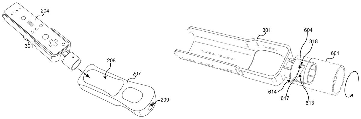
FIG. 3Bprovides another view angle of coupling mechanism312. As illustrated, the couple mechanism is configured with cylindrical protrusions318, designed to fit into tracks or threads of an attachment portion (not shown) when the attachment portion is coupled with handle portion301. With these protrusions318, an attachment portion (not shown) can be attached to the handle portion in a removable fashion. As described below, these cylindrical protrusions are configured to engage thread-like grooves in a sleeve of an attachment portion such that the attachment portion can be screwed or twisted onto the handle portion. In some embodiments, each protrusion318is specifically is also designed to engage a lock mechanism that is provided at the end of a track or thread of the attachment portion. These protrusions may be configured to different other designs in such a way as to be compatible with other different attachment portions or, alternatively, compatible with several attachment portions at once. The protrusions may also be configured such that the attachment portion attaches to a handle portion in predetermined manner or orientation.
FIG. 3Cis a side view of handle portion301, andFIG. 3Dis a top view of the same. As can be seen inFIGS. 3C and 3D, the cutaway portion309at the bottom of the handle portion is shaped so as to conform to the trigger recess of a Wii® controller, such as controller204. As previously stated above, the cutaway portion309can take on different shapes or dimensions depending on the controller with which the accessory is implemented. These views also illustrate the example spring tabs321at the distal end of handle portion301, used to hold the controller in place once placed into handle portion301.
In some emboidments, a multiple piece accessory having the handle portion separate from the head portion facilitates attachment of the soft skin to the outside of a handle portion. In one embodiment the handle portion is configured such that a soft skin that would normally be used with a Wii® remote (e.g., the example controller illustrated inFIGS. 2A and 2B). For example, because the skin included with the Wii® remote has an opening so as to not obscure the infrared window on the proximal end of the controller, the coupling mechanism in the illustrated example is sized so as to allow the handle portion to be inserted through this opening in the skin, allowing the skin to be diposed over (e.g., attached or slipped around) the gripping area of the handle portion. As such, in operation, the remote can be placed in the handle portion, snapped into place, and then the soft skin can be disposed over the handle portion and the Wii® remote control contained therein. With the soft skin in place, various implements with mating heads can be subsequently attached to the handle portion using a coupling mechanism in accordance with an embodiment.
FIGS. 4A-4Eillustrate the use of the example handle portion301ofFIGS. 3A-3Dwith example game controller204ofFIGS. 2A-2B, in accordance with one embodiment of the present invention. As illustrated byFIGS. 4A-4E, and previously stated above, handle portion301is configured to conform to the form factor of a Wii® remote control (i.e., controller204).FIG. 4Dadditionally illustrates how the cut out309of handle portion301provides access to the Wii® remote trigger211of controller204, and opening308of handle portion301provides an aperture for the infrared window of controller301.
FIGS. 5A-5Eillustrate configuration501where example handle portion301ofFIGS. 3A-3Dis used with example game controller204and example controller cover/sheath207ofFIGS. 2A-2B, in accordance with one embodiment of the present invention. As illustrated inFIGS. 5A-5Eand described above, handle portion301is sized sufficiently to allow the handle portion to be inserted through an opening208in the skin207, allowing the skin to be disposed over the gripping area of handle portion301. Also illustrated inFIGS. 5A-5E, is the opening209in the skin207configured into the skin as to not obscure the infrared window on the proximal end of controller301. As illustrated, coupling mechanism312is sized to be inserted through opening209and protrude outside skin207to be ready for attachment with a head portion (not shown). Further illustrated inFIG. 5C, a top-down view of the couple mechanism, is opening308, which like the opening of209of skin207also prevents handle portion301from obscuring the infrared window205on the proximal end of controller204when a head portion is not attached to handle301. Additionally,FIG. 5Dillustrates how both the handle portion301and skin207have a cut out to allow access to the Wii® remote trigger211of controller204.
Although a number of configurations can be used to attach the attachment portion to the handle portion, the examples described herein show an attachment portion having a sleeve that is molded in multiple pieces for assembly and manufacturing purposes. Other processes and techniques can be used to create the sleeve for attachment to the coupling mechanism of the handle portion.
FIGS. 6A-6Gare diagrams illustrating an example attachment portion of an attachment apparatus in accordance with one embodiment of the present invention. Specifically,FIGS. 6A-6Cillustrate a sleeve601of an attachment portion once it is assembled. The sleeve601is configured to accept and attach to a coupling mechanism, identical or similar to couple mechanism312. The illustrated sleeve601is assembled from two pieces, piece607and piece610. It would be appreciated by one of ordinary skill in the art that other embodiments of the present invention may be suitable created of more than two pieces or, alternatively, be constructed as one unitary piece. The example sleeve of the attachment portion illustrated inFIGS. 6A-6Gincludes tabs and other attachment mechanisms that allow the multiple pieces (607,610) of sleeve601to be assembled into a single piece. Glues or plastic welds may be used to affix the attachment portion halves together to form the sleeve.
Turning now toFIG. 6D, which illustrates piece607in further detail, andFIG. 6E, which illustrates piece610in further detail, both pieces607and610are configured with interior surfaces having tracks, grooves or threads613, in the sleeve601of the attachment portion. As such, the internal circumference of sleeve601is configured to allow protrusions of a handle portion's coupling mechanism to engage the threads, thereby allowing a handle portion to be threaded into place with the attachment portion. In the illustrated embodiment, each of these threads613is configured to accept a protrusion configured on a couple mechanism, such as protrusion318on couple mechanism312. When an attachment portion is attaching itself to a couple mechanism, a protrusion of the couple mechanism would begin at the start614of the thread613, where the protrusion is accepted by the attachment portion, and then guided into place at the end617of the thread613. In the present embodiment, thread613ends with a locking mechanism617, which engages the protrusion once it reaches the end of the thread, thereby locking the attachment portion to the handle portion. Such is shown inFIG. 7, where the use of the example handle portion301ofFIGS. 3A-3Dis used with the example sleeve601ofFIGS. 6A-6Cis illustrated.
In one embodiment, the threads are configured such that the sleeve is required to compress the soft skin, allowing the soft skin to act as a spring lock for the sleeve. For example, continuing with reference toFIGS. 6D and 6E, locking mechanism617may be positioned such that in order for sleeve601to attach to handle portion301and lock into place (via couple mechanism312), skin207, which is surrounding handle portion301, would need to be compressed. In one example, this may be achieve by configuring threads613to extend to a depth into sleeve601such that sleeve601is in contact with the soft skin on the handle portion when the handle portion is attached to the coupling mechanism of the handle portion. By doing so, skin207due to its elastomeric properties would act as a spring, applying pressure on sleeve601such sleeve601is pushes outward. This would result in the protrusions, such as protrusions318of couple mechanism312, to engage with their respective locking mechanisms317. Other forms of couple and locking mechanisms may be used in order to lock an attachment portion to a handle portion in accordance with the present invention.
Accordingly, some pressure is required in such embodiments to compress the soft skin to allow the attachment portion to be threaded onto the handle and locked into place. Likewise, pressure is required to compress the elastomeric skin to disengage the attachment portion from the handle portion. The threads and locking mechanism may be configured in such a way that sufficient pressure is required to compress the elastomeric skin such that a snug fit provided.
Once assembled, the pieces607and610form a sleeve601configured with an interior surface having 2 thread-length tracks inside sleeve601. As described above, the slots or tracks on the inside of the cylinder are sized to accept the protrusions318on coupling mechanism312, such that the coupling mechanism can be threaded into the sleeve. In some embodiments, the 2 threads illustrated may extend approximately 180° around the inner circumference of the sleeve. By doing so, the attachment portion to be attached to the handle portion with approximately a one half turn.
FIGS. 6F and 6Gillustrate a bayonet attachment mechanism620used in conjunction with sleeve601in order to complete the remainder of the attachment portion in accordance with some embodiments of the invention. In particular, with use of the bayonet attachment mechanism, additional components may be attached to attachment portion in order to complete the final, desired shape of the attachment portion. For example, bayonet mechanism620would allow a component shaped as a tennis racket, golf club, baseball bat, hockey stick, lacrosse stick, or fishing rod to be attached to the sleeve601, thereby completing the construction of the attachment portion.FIGS. 9A and 9Billustrate such a completed attachment portion, and how assembly of the final attachment portion is facilitated using a bayonet mechanism. As illustrated inFIGS. 9A and 9B, an example tennis sports attachment portion901combining a sleeve601with a tennis racket shaped component904having a bayonet mechanism907. It should be noted that although a bayonet mechanism is illustrated in this embodiment, any of a number of mechanisms can be used to attach the sleeve assembly to the remainder of the attachment portion.
Continuing with reference toFIGS. 6E and 6F, a hole629in the bayonet mechanism620is provided to allow separate pieces of the sleeve of the attachment portion (e.g.,607and610) to be joined together using a screw or like mechanism, while concurrently securing the bayonet mechanism620to the sleeve. Also illustrated are cutouts623of bayonet mechanism620, which correspond to complementary protrusions626in the sleeve and facilitate alignment of the bayonet for assembly. Other mechanisms including glues, welds and other attachment means can be used to assemble the sleeve.
Referring now toFIGS. 8A-8E, the diagrams illustrate the use of example handle portion301ofFIGS. 3A-3Din conjunction with example sleeve601ofFIGS. 6A-6C, and example game controller204and example controller cover/sheath207ofFIGS. 2A-2B, in accordance with one embodiment of the present invention.
Although the invention is described above in terms of various exemplary embodiments and implementations, it should be understood that the various features, aspects and functionality described in one or more of the individual embodiments are not limited in their applicability to the particular embodiment with which they are described, but instead can be applied, alone or in various combinations, to one or more of the other embodiments of the invention, whether or not such embodiments are described and whether or not such features are presented as being a part of a described embodiment. Thus, the breadth and scope of the present invention should not be limited by any of the above-described exemplary embodiments.
Terms and phrases used in this document, and variations thereof, unless otherwise expressly stated, should be construed as open ended as opposed to limiting. As examples of the foregoing: the term “including” should be read as meaning “including, without limitation” or the like; the term “example” is used to provide exemplary instances of the item in discussion, not an exhaustive or limiting list thereof; the terms “a” or “an” should be read as meaning “at least one,” “one or more” or the like; and adjectives such as “conventional,” “traditional,” “normal,” “standard,” “known” and terms of similar meaning should not be construed as limiting the item described to a given time period or to an item available as of a given time, but instead should be read to encompass conventional, traditional, normal, or standard technologies that may be available or known now or at any time in the future. Likewise, where this document refers to technologies that would be apparent or known to one of ordinary skill in the art, such technologies encompass those apparent or known to the skilled artisan now or at any time in the future.
The presence of broadening words and phrases such as “one or more,” “at least,” “but not limited to” or other like phrases in some instances shall not be read to mean that the narrower case is intended or required in instances where such broadening phrases may be absent. The use of the term “module” does not imply that the components or functionality described or claimed as part of the module are all configured in a common package. Indeed, any or all of the various components of a module, whether control logic or other components, can be combined in a single package or separately maintained and can further be distributed in multiple groupings or packages or across multiple locations.
Claims
- A controller attachment apparatus, comprising: a handle portion comprising a recess configured to accept and retain a controller and further comprising a first coupler disposed on an end of the handle portion;an attachment portion comprising a second coupler disposed thereon and configured to mate with the first coupler, the attachment portion configured to be releasably affixed to the handle portion by the first and second couplers;and a flexible covering configured to be removably disposed on and covering at least a part of the handle portion and comprising a first opening conforming to the first coupler, and configured to apply pressure to the first or second coupler to thereby facilitate locking the first and second couplers in a coupled configuration, wherein the flexible cover comprises a second opening to provide access to the controller.
- A controller attachment apparatus of claim 1 , wherein the attachment portion is shaped like a spotting good or a weapon.
- The controller attachment apparatus of claim 2 , wherein the sporting, good is a tennis racket, paddle tennis racket, golf club, baseball bat, hockey stick, lacrosse stick, or fishing rod.
- The controller attachment apparatus of claim 2 , wherein the weapon is a sword, dagger, blade, a light saber, a gun, or a phaser.
- The controller attachment apparatus of claim 1 , wherein the handle portion comprises a holding mechanism to retain the controller after the controller is disposed into the handle portion.
- The controller attachment apparatus of claim 5 , wherein the holding mechanism is of sufficient flexibility to enable the controller to be clipped into and removed from the handle portion.
- The controller attachment apparatus of claim 5 , wherein the holding mechanism is a tab.
- The controller attachment apparatus of claim 1 , wherein the handle portion comprises a cutaway portion that is configured to allow access to a controller input or port after the controller is placed into the handle portion.
- The controller attachment apparatus of claim 8 , wherein the controller input is a button, directional pad, joystick, switch, or trigger.
- The controller attachment apparatus of claim 1 , wherein the handle portion and the attachment portion are a unitary piece.
- The apparatus of claim 1 , wherein the first coupler is a twist mechanism, sliding mechanism or a snap-on mechanism.
- The controller attachment apparatus of claim 1 , wherein the second coupler comprises a sleeve disposed on the attachment portion configured to accept the first coupler, and the controller attachment apparatus further comprises: a protrusion disposed on the sleeve or the second coupler, a track configured to accept the protrusion when the first coupler is inserted into the sleeve, and a locking mechanism positioned at the end of the track configured to engage the protrusion once the attachment mechanism is inserted into the sleeve and the protrusion reaches the locking mechanism.
- The controller attachment apparatus of claim 12 , wherein the flexible covering comprises an elastic material and the length of the track and the position of the locking mechanism are such that the elastic covering assists the locking mechanism in engaging the protrusion.
- A controller attachment apparatus, comprising: a handle comprising a recess configured to releasably retain a controller and further comprising a first coupler;an attachment comprising a second coupler configured to mate with the first coupler, wherein the attachment is configured to be removably attached to the handle by engagement of the first and second couplers, wherein the second coupler comprises a sleeve portion configured to detachably couple with the first coupler;wherein the first coupler is further configured to allow a flexible covering to be removably disposed over the handle portion, wherein the flexible cover applies pressure to the first or second coupler to thereby facilitate locking the first and second couplers in a coupled configuration when the attachment and sleeve portion are coupled, and wherein the flexible covering comprises an opening to provide access to the controller.
- The controller attachment apparatus of claim 14 , wherein the coupling mechanism is further configured to allow the flexible covering to be removably disposed over the handle portion when the attachment is decoupled from the sleeve portion.
- The controller attachment apparatus of claim 14 , wherein the compressible portion of the flexible covering is near the coupling mechanism when the flexible covering is removably disposed over the handle portion.
Disclaimer: Data collected from the USPTO and may be malformed, incomplete, and/or otherwise inaccurate.