U.S. Pat. No. 8,553,935
Computer interface employing a manipulated object with absolute pose detection component and a display
AssigneeElectronic Scripting Products Inc
Issue DateMay 25, 2011
Valve Corp. v. Electronic Scripting Products
IPR2019-00062
Decision Issued: April 2, 2019

On April 2, 2019, The Patent Trial and Appeal Board (PTAB) declined Valve’s petition to institute an Inter Partes Review of U.S. Patent No. 9,235,934 (the ‘934 Patent) for being a repetitive challenge to the patent. The genesis of this action is the patent infringement lawsuit, Electronic Scripting Products, Inc. v. HTC America, Inc., No. 3:17-cv-05806-RS, filed on October 9, 2017, in the Northern District of California. Electronic Scripting claimed HTC and Valve had infringed the ‘934 Patent and U.S. Patent No. 8,553,935 by integrating Valve’s technology into HTC’s VIVE headsets. On January 25, 2018, Electronic Scripting voluntarily dismissed Valve from the lawsuit, but not HTC, who in turn filed a first IPR petition on the ‘934 Patent. The PTAB declined to institute an IPR based on the first petition because HTC failed to show that any of the challenged claims would likely be invalid. Five months after the PTAB rejected HTC’s first petition, Valve submitted additional petitions to the PTAB based on other grounds, which the PTAB suggested were based on lessons learned from the denial of the first petition.
Electronic Scripting asked the PTAB to exercise their discretion to reject Valve’s additional IPR petitions under 35 U.S.C. § 314(a) because Valve was seeking to invalidate the same claims as HTC’s earlier IPR and is “similarly situated” to HTC. Valve counters by arguing the only similarity it has with HTC is wishing to see the ‘934 Patent invalidated, but otherwise, the two companies are unrelated. When it comes to a petition on a patent that the PTAB has already reviewed, the board applies a seven-factor test to determine if it should grant the second petition, as set forth in General Plastics. Case IPR2016-01357, slip op. at 16 (PTAB Sept. 6, 2017):
- whether the same petitioner previously filed a petition directed to the same claims of the same patent;
- whether at the time of filing of the first petition the petitioner knew of the prior art asserted in the second petition or should have known of it;
- whether at the time of filing of the second petition the petitioner already received the patent owner’s preliminary response to the first petition or received the Board’s decision on whether to institute review in the first petition;
- the length of time that elapsed between the time the petitioner learned of the prior art asserted in the second petition and the filing of the second petition;
- whether the petitioner provides adequate explanation for the time elapsed between the filings of multiple petitions directed to the same claims of the same patent;
- the finite resources of the Board; and
- the requirement under 35 U.S.C. § 316(a)(11) to issue a final determination not later than 1 year after the date on which the Director notices institution of review. Id.
The PTAB found that every factor weighed against instituting Valve’s later IPR petitions because of how closely linked Valve is to the litigation and HTC’s previous IPR petition. The first factor weighed against Valve because the PTAB found Valve’s petition was directed at the same claims as the previous IPR. Factor two weighed against institution due to the new prior art Valve asserted in its petition being fairly easy to find, which meant HTC should have known it existed. The third factor weighed against instituting the IPR as a result of Valve using the outcome of the first petition to help craft its petition.
Factors four and five weighed against Valve because of the five-month delay on Valve’s part to file the petition. The Board explored the impact of the Federal Circuit’s Click-to-Call decision in factors four and five. Prior to the Click-to-Call decision, Valve was not time barred because Electronic Scripting had dismissed the complaint against Valve. However, the Click-to-Call decision changed the law, and Valve was put in a position where it had to file or Valve would become time-barred. The PTAB reviewed the situation but ultimately decided that this did not impact the fairness of Valve’s delay in filing its IPR petitions. Finally, factors six and seven weighed against Valve because allowing similarly situated parties to continuously petition for IPRs would drain the resources of the PTAB.
With all seven factors weighing against instituting Valve’s IPR petition, the PTAB denied institution. Because institution was denied here, Valve may still be able to challenge the validity of the patents back in the district court, but as noted above Valve is no longer a party to the ongoing litigation. See Shaw Industries Group, Inc. v. Automated Creel Systems, Inc., 817 F.3d 1293 (Fed. Cir. 2016). We will continue to follow this case, and provide updates when available.
Illustrative Figure
Abstract
A system that has a remote control, e.g., a wand, equipped with a relative motion sensor that outputs data indicative of a change in position of the wand. The system also has one or more light sources and a photodetector that detects their light and outputs data indicative of the detected light. The system uses one or more controllers to determine the absolute position of the wand based on the data output by the relative motion sensor and by the photodetector. The data enables determination of the absolute pose of the wand, which includes the absolute position of a reference point chosen on the wand and the absolute orientation of the wand. To properly express the absolute parameters of position and/or orientation of the wand a reference location is chosen with respect to which the calculations are performed. The system is coupled to a display that shows an image defined by a first and second orthogonal axes such as two axes belonging to world coordinates (Xo,Yo,Zo). The one or more controllers are configured to generate signals that are a function of the absolute position of the wand in or along a third axis for rendering the display. To simplify the mapping of a real three-dimensional environment in which the wand is operated to the cyberspace of the application that the system is running, the third axis is preferably the third Cartesian coordinate axis of world coordinates (Xo,Yo,Zo).
Description
DETAILED DESCRIPTION To appreciate the basic aspects of the present invention, we initially turn to a simple version of an apparatus10in accordance with the invention, as shown inFIG. 1. Apparatus10has a manipulated object14whose motion40in a real three-dimensional environment18is expressed by absolute pose data12. Apparatus10processes absolute pose data12that describe the absolute pose of manipulated object14at a number of measurement times ti. Thus, successive pose data12collected at the chosen measurement times describe the motion that manipulated object14executes or is made to execute by a user38. Manipulated object14is any object that is moved either directly or indirectly by a user38and whose pose when object14is stationary or in motion yields useful absolute pose data12. For example, manipulated object14is a pointer, a wand, a remote control, a three-dimensional mouse, a game control, a gaming object, a jotting implement, a surgical implement, a three-dimensional digitizer, a digitizing stylus a hand-held tool or any utensil. In fact, a person skilled in the art will realize that a manipulated object14can be even be an entire device such as a cell phone or a smart object that is handled by user38to produce meaningful motion40. In the present case, manipulated object14is a pointer that executes motion40as a result of a movement performed by the hand of a user38. Pointer14has a tip16that will be used as a reference point for describing its absolute pose in real three-dimensional environment18. In general, however, any point on object14can be selected as reference point16, as appropriate or convenient. Pointer14has an on-board optical measuring arrangement22for optically inferring its absolute pose with the aid of one or more invariant features32,34,36disposed at different locations in real three-dimensional environment18. Invariant features32,34,36are high optical contrast features such as edges of objects, special markings, or light sources. In the present embodiment, invariant feature32is an edge of an object such as a ...
DETAILED DESCRIPTION
To appreciate the basic aspects of the present invention, we initially turn to a simple version of an apparatus10in accordance with the invention, as shown inFIG. 1. Apparatus10has a manipulated object14whose motion40in a real three-dimensional environment18is expressed by absolute pose data12. Apparatus10processes absolute pose data12that describe the absolute pose of manipulated object14at a number of measurement times ti. Thus, successive pose data12collected at the chosen measurement times describe the motion that manipulated object14executes or is made to execute by a user38.
Manipulated object14is any object that is moved either directly or indirectly by a user38and whose pose when object14is stationary or in motion yields useful absolute pose data12. For example, manipulated object14is a pointer, a wand, a remote control, a three-dimensional mouse, a game control, a gaming object, a jotting implement, a surgical implement, a three-dimensional digitizer, a digitizing stylus a hand-held tool or any utensil. In fact, a person skilled in the art will realize that a manipulated object14can be even be an entire device such as a cell phone or a smart object that is handled by user38to produce meaningful motion40.
In the present case, manipulated object14is a pointer that executes motion40as a result of a movement performed by the hand of a user38. Pointer14has a tip16that will be used as a reference point for describing its absolute pose in real three-dimensional environment18. In general, however, any point on object14can be selected as reference point16, as appropriate or convenient.
Pointer14has an on-board optical measuring arrangement22for optically inferring its absolute pose with the aid of one or more invariant features32,34,36disposed at different locations in real three-dimensional environment18. Invariant features32,34,36are high optical contrast features such as edges of objects, special markings, or light sources. In the present embodiment, invariant feature32is an edge of an object such as a table (object not shown), invariant feature34is a special marking, namely a cross, and feature36is a light source. It is possible to use features32,34,36that are all located in a plane (coplanar) or else at arbitrary locations (non-coplanar) within real three-dimensional environment18as conveniently defined by global or world coordinates (Xo,Yo,Zo). The limitation is that, depending on the type of features32,34,36a sufficient number of them have to be visible to on-board optical measuring arrangement22at measurement times ti, as described in more detail below.
In the present embodiment the world coordinates (Xo,Yo,Zo) chosen to parameterize real three-dimensional environment18are Cartesian. A person skilled in the art will recognize that other choices including polar, cylindrical or still different coordinate systems can be employed. In addition, it will be appreciated that features32,34,36can be temporarily or permanently affixed at their spatial locations as required for measuring the pose of pointer14. Indeed, the spatial locations of features32,34,36can be changed in an arbitrary manner, as long as on-board optical measuring arrangement22is appraised of their instantaneous spatial locations at times ti.
The spatial locations of features32,34,36, whether temporary or permanent, are conveniently expressed in world coordinates (Xo,Yo,Zo). Furthermore, if possible, the spatial locations of features32,34and36are preferably such that at least a subset of them is visible to on-board optical measuring arrangement22in all absolute poses that pointer14is expected to assume while undergoing motion40. Invariant features32,34,36are used in deriving a relative or absolute position of tip16of pointer14in real three-dimensional environment18. Features32,34,36are also used for optically inferring the remaining portion of the absolute pose, i.e., the orientation of pointer14.
A number of optical measurement methods using optical measuring arrangement22to infer the relative or absolute pose of pointer14can be employed. In any of these methods, arrangement22uses one or more on-board components to obtain pose data12in accordance with any well-known absolute pose recovery technique including geometric invariance, triangulation, ranging, path integration and motion analysis. In some embodiments arrangement22has a light-measuring component with a lens and an optical sensor that form an imaging system. In other embodiments arrangement22has an active illumination component that projects structured light or a scanning component that projects a scanning light beam into environment18and receives a scattered portion of the scanning light beam from features32,34. Specific examples of the various possible components will be explained in detail below.
Apparatus10has a processor26for preparing absolute pose data12corresponding to absolute pose of pointer14and for identifying a subset48of absolute pose data12required by an application28. Specifically, application28uses subset48which may contain all or less than all of absolute pose data12. Note that processor26can be located on pointer14or it can be remote, e.g., located in a remote host device, as is the case in this embodiment.
A communication link24is provided for sending absolute pose data12to application28. Preferably, communication link24is a wireless communication link established with the aid of a wireless transmitter30mounted on pointer14. In embodiments where processor26and application28are resident on pointer14, communication link24can be a direct electrical connection. In still other embodiments, communication link24can be a wired remote link.
During operation user38holds pointer14in hand and executes a movement such that pointer14executes motion40with respect to invariant features32,34,36in world coordinates (Xo,Yo,Zo) that parametrize real three-dimensional environment18. For better visualization, motion40is indicated in dashed lines42,44that mark the positions assumed by tip16and end46of pointer14during motion40. For the purposes of this invention, line42is referred to as the trace of tip16. In some specific applications of the present invention, trace42of tip16may be confined to a surface embedded in real three-dimensional environment18. Such surface can be plane, e.g., a planar jotting surface, or it can be curved.
Motion40may produce no movement of end46or tip16, i.e., no trace42. In fact, motion40is not limited by any parameter other than those of standard mechanics of rigid body motion known form classical mechanics. Accordingly, changes in orientation of pointer14are considered to be motion40. Likewise, changes in position of tip16(or any other reference point) in (x,y,z) coordinates conveniently expressed in world coordinates (Xo,Yo,Zo) are also considered to be motion40. In the present case, orientation of pointer14is described by inclination angle θ, rotation angle φ and roll angle ψ referenced with respect to a center axis C.A. of pointer14. A change in at least one of these angles constitutes motion40.
In the present case, tip16moves along line42as pointer14is inclined with respect to a normal Z′ at inclination angle θ equal to θo. For simplicity, normal Z′ is selected to be parallel to the Zoaxis of world coordinates (Xo,Yo,Zo). Furthermore, rotation and roll angles φ, ψ are equal to To, ψorespectively. For convenience, in this embodiment angles θ, φ and ψ are Euler angles. Of course, other angles can be used to describe the orientation of pointer14. In fact, a person skilled in the art will appreciate that any convention for describing the rotations of pointer16can be adapted for this description. For example, the four Carlyle-Klein angles, the direction cosines, quaternions or still other descriptors of tilt, yaw and roll can be employed in such alternative conventions.
FIGS. 2A-Cillustrate a convention for describing the orientation of pointer14using Euler angles θ, φ, ψ. Pointer14has a length l measured from tip16at the origin of non-rotated object coordinates (X′,Y′,Z′) as shown inFIG. 2A. Center axis C.A. is collinear with the Z′ axis, and it passes through tip16and the origin of non-rotated object coordinates (X′,Y′,Z′). In the passive rotation convention used herein, object coordinates will be attached to pointer14while pointer14is rotated from its initial upright position in which Z′ is parallel to Zoof world coordinates (Xo,Yo,Zo).
Now,FIG. 2Aillustrates a first counterclockwise rotation by first Euler angle φ of object coordinates (X′,Y′,Z′) about the Z′ axis. This rotation of the object coordinates does not affect the Z′ axis so once rotated Z″ axis is collinear with non-rotated Z′ axis (Z″=Z′). On the other hand, axes X′ and Y′ are rotated by first Euler angle φ to yield once rotated axes X″ and Y″.
FIG. 2Billustrates a second counterclockwise rotation by second Euler angle θ applied to once rotated object coordinates (X″,Y″,Z″). This second rotation is performed about the once rotated X″ axis and therefore it does not affect the X″ axis (X′″=X″). On the other hand axes Y″ and Z″ are rotated by second Euler angle θ to yield twice rotated axes Y′″ and Z′″. This second rotation is performed in a plane Π containing once rotated axes Y″, Z″ and twice rotated axes Y′″, Z′″. Note that axis C.A. of pointer14is rotated counterclockwise by second Euler angle θ in plane Π and remains collinear with twice rotated axis Z′″.
A third counterclockwise rotation by third Euler angle ψ is applied to twice rotated object coordinates (X′″,Y′″,Z′″) as shown inFIG. 1C. Rotation by ψ is performed about twice rotated axis Z′″ that is already collinear with object axis Z rotated by all three Euler angles. Meanwhile, twice rotated axes X′″,Y′″ are rotated by ψ to yield object axes X,Y rotated by all three Euler angles. Object axes X,Y,Z rotated by all three Euler angles φ, θ and ψ define Euler rotated object coordinates (X,Y,Z). Note that tip16of pointer14remains at the origin of all object coordinates during the Euler rotations.
Now, referring back toFIG. 1, the absolute pose of pointer14includes its orientation, i.e., Euler angles (φ, θ, ψ), and position of tip16, i.e., the coordinates (x,y,z) of tip16that was chosen as the reference point. The orientation of pointer14and position of tip16are expressed in world coordinates (Xo,Yo,Zo). World coordinates (Xo,Yo,Zo) have a reference location, in this case the world origin (0,0,0) that can be used to describe an absolute position of tip16. In fact, world coordinates (Xo,Yo,Zo) can be used for an absolute measure of any parameter(s) of the pose of pointer14. Alternatively, any parameter(s) of the pose of pointer14can be described in a relative manner, e.g., with reference to non-stationary or relative coordinates (Xi,Yi,Zi) or simply with respect to the previous pose.
For the purposes of the present invention, it is important to be able to optically infer, at least from time to time, the absolute pose of pointer14. To do this, one relates Euler rotated object coordinates describing the orientation of pointer14to world coordinates (Xo,Yo,Zo). Note that the orientation of object axis Z′ in world coordinates (Xo,Yo,Zo) prior to the three Euler rotations is normal to plane (Xo,Yo). Second Euler angle θ defines the only counterclockwise rotation of object coordinates that is not about an object Z axis (this second rotation is about the X″=X′″ axis rather than axis Z′, Z″ or Z′″). Thus, Euler angle θ is an inclination angle θ between the completely Euler rotated object axis Z or axis C.A. and original object axis Z′, which is normal to plane (Xo,Yo).
Optical measuring arrangement22infers the absolute pose of pointer14during motion40at measurement times tiand processor26prepares the corresponding absolute pose data12.
Note that absolute pose data12consist of inferred values of parameters (φ,θ,ψ,x,y,z) at measurement times ti. Invariant features32,34,36are located at positions that are defined in world coordinates (Xo,Yo,Zo). These positions stay fixed at least during measurement and usually permanently. Knowledge of the absolute positions of features32,34,36in world coordinates (Xo,Yo,Zo) allows the optical measuring arrangement22to describe the absolute pose of pointer14with absolute pose data12expressed in parameters (φ,θ,ψ,x,y,z) at measurement times tiin Euler rotated object coordinates within world coordinates (Xo,Yo,Zo). The expression of absolute pose data is preferably with respect to a reference location such as world origin (0,0,0) of world coordinates (Xo,Yo,Zo).
Of course, alternative locations within world coordinates can also be chosen as reference locations with respect to which the absolute pose of pointer14is expressed. For example, the center of invariant feature34may be chosen as the reference location and the locations of reference point16on pointer14at n measurement times tican be denoted by corresponding n vectors Di, as shown in the drawing.
The frequency with which the absolute pose is inferred, i.e., the times ti, depends on the use of absolute pose data12corresponding to that absolute pose and the desired performance, e.g., temporal resolution. It should be noted that periodic optical inference of absolute pose is not limited to any predetermined times tior frequency schedule. In other words, the times between any two successive optical inferences or measurements of the absolute pose can be arbitrary. Preferably, however, arrangement22infers the absolute pose at a frequency that is high enough to obtain absolute pose data12that describe motion40at the temporal resolution required by application28.
Wireless transmitter30of communication link24sends absolute pose data12here defined by parameters (φ,θ,ψ,x,y,z) collected at measurement times tito processor26. Absolute pose data12can be transmitted continuously, in bursts, in parts, at arbitrary or preset times or as otherwise desired. Processor26prepares a subset48of absolute pose data12, for example the absolute position (x,y,z) of tip16and sends it to application28. Application28uses absolute position (x,y,z) of tip16at measurement times tito chart trace42of tip16as pointer14executes motion40. In other words, unit28recovers trace42corresponding to the movement of tip16. Note that the resolution of trace42in absolute space can be improved by increasing the sample of measurements of absolute trace points traversed in environment18by increasing the frequency of measurement times ti.
It should also be noted that pose data12should be formatted for appropriate communications between transmitter30, processor26and application28. Any suitable communication and formatting standards, e.g., IEEE interface standards, can be adapted for these purposes. For specific examples of formatting standards the reader is referred to Rick Poyner, LGC/Telegraphics, “Wintab™ Interface Specification: 16-bit and 32-bit API Reference”, revision of May 9, 1996; Universal Serial Bus (USB), “Device Class Definition for Human Interface Devices (HID)”, Firmware Specification, USB Implementers' Forum, Jun. 27, 2001 and six-degree of freedom interface by Ulrica Larsson and Johanna Pettersson, “Development and evaluation of a 6DOF interface to be used in a medical application”, Thesis, Linkopings University, Department of Science and Technology, Sweden, Jun. 5, 2002.
The orientation portion of absolute pose data12, i.e., Euler angles (φ,θ,ψ) can also be used in the present embodiment. Specifically, processor26can prepare additional subsets or send all of the orientation parameters (φ,θ,ψ) of absolute pose data12as a single subset to application28or to a different application or device serving a different function. Any mix of orientation (φ,θ,ψ) and position (x,y,z) data derived from absolute pose data12can be used in subset48. In fact, in some embodiments processor26keeps all absolute pose data12in subset48such that all of its parameters (φ,θ,ψ,x,y,z) can be used by application28. This is done when application28has to reconstruct the entire motion40of pointer14and not just trace42of tip16. For example, this is done when application28includes a motion-capture application. Once again, the temporal resolution of motion40can be improved by increasing the frequency of measurement times ti. Note that in this case parameters of pose data12that vary slowly are oversampled.
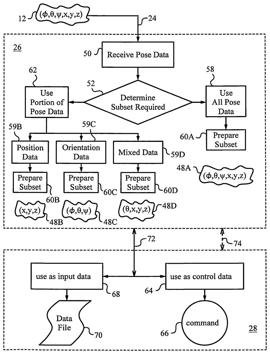
InFIG. 3a block diagram illustrates the processing of absolute pose data12by processor26and its use by application28in more detail. In a first step50, absolute pose data12is received by processor26via communication link24. In a second step52, processor26determines which portion or subset48of absolute pose data12is required. This selection can be made based on application28. For example, when application28is a trace-capture application that charts trace42, then only position data of tip16, i.e., (x,y,z) of this reference point16need to be contained in subset48. On the other hand, when application28is a motion-capture application, then all absolute pose data12are contained in subset48.
In step58all absolute pose data12are selected and passed to a subset formatting or preparing step60A. In step60A data12is prepared in the form of subset48A as required by application28. For example, data12is arranged in a particular order and provided with appropriate footer, header and redundancy bits (not shown), or as otherwise indicated by data porting standards such as those of Rick Poyner, LGC/Telegraphics (op. cit.).
In step62, only a portion of data12is selected. Three exemplary cases of partial selection are shown. In the first case, only position data is required by application28. Hence, in a step59B only position data (x,y,z) are selected and the remaining data12is discarded. In a subsequent step60B, position data (x,y,z) are prepared in the form of subset48B as required by application28and/or as dictated by the porting standards.
In a second case, in a step59C, only orientation data (φ,θ,ψ) are selected and the rest of data12are discarded. Then, in a step60C, orientation data (φ,θ,ψ) are prepared in the form of a subset48C for use by application28.
In the third case, in a step59D, a mix of data12, including some position data and some orientation data are selected and processed correspondingly in a step60D to prepare a subset48D.
A person skilled in the art will appreciate that the functions described can be shared between processor26and application28, e.g., as required by the system architecture and data porting. standards. For example, some preparation of subset48can be performed by application28upon receipt. It should also be noted that in some embodiments data12can be pre-processed by transmitter30or post-processed at any point before or after preparation of the corresponding subset48in accordance with any suitable algorithm. For example, a statistical algorithm, such as a least squares fit can be applied to data12derived at different times tior to successive subsets48. Furthermore, quantities such as time derivatives of any or all parameters, i.e.,
(ⅆxⅆt,ⅆyⅆt,ⅆzⅆt,ⅆϕⅆt,ⅆθⅆt,ⅆψⅆt),
can be computed. Also, various sampling techniques, e.g., oversampling can be used.
Subset48is transmitted to application28via a communication channel72. Application28receives subset48as an input that is treated or routed according to its use. For example, in a step64, subset48is used as control data. Thus, subset48is interpreted as an executable command66or as a part of an executable command. On the other hand, in a step68, subset48is used as input data and saved to a data file70.
In one embodiment, application28passes information to processor26to change the selection criteria for subset48. Such information can be passed via communication channel72or over an alternative link, e.g., a feedback link74. For example, application28requests subset48A to be transmitted and uses subset48A as input data for data file70. At other times, application28requests subset48C to be transmitted and uses subset48C as command data for executable command66. Alternatively, processor26can indicate a priori whether any subset48should be treated as input data or control data. In still another alternative, user38can indicate with the aid of a separate apparatus, e.g., a switch mounted on pointer14(not shown), whether subset48is intended as control data or input data. A person skilled in the art will recognize that there exist a large number of active and passive methods for determining the interpretation and handling of data being transmitted in subset48by both processor26and application28.
In a specific application28, subset48contains only position data (x,y,z) of reference point or tip16of pointer14collected at a number of measurement times ti. This subset corresponds to individual points along trace42and is an absolute trace expressed by points referenced with respect to origin (0,0,0) of world coordinates (Xo,Yi,Zo). For example, in a particular applications28trace42may be treated as a digital ink trace that is designed to be handled as input data or command data. Alternatively, the absolute points forming trace42can be expressed in world coordinates (Xo,Yo,Zo) with respect to a reference location other than world origin (0,0,0).FIG. 1shows that one such alternative reference location can be the center of feature34, whose absolute position in world coordinates (Xo,Yo,Zo) is known. In this case, vectors Do, . . . Di, . . . Dndescribe the absolute position of the points of trace42collected at successive measurement times to, . . . ti, . . . tn.
In practice, efficient inference of the absolute pose of pointer14in terms of absolute pose data expressed in parameters (φ,θ,ψ,x,y,z) representing Euler rotated object coordinates expressed in world coordinates (Xo,Yo,Zo) with respect to a reference location, such as world origin (0,0,0) imposes a number of important requirements. Since pointer14may be moving in a close-range environment18the field of view of on-board optical measuring arrangement22must be large. This is particularly crucial in situations where arrangement22has to tolerate frequent occlusions of one or more of invariant features32,34,36. Such conditions arise when user38operates pointer14in a close-range home, gaming or work environment18, i.e., in a room, a cubicle or other confined real space. Also, if full motion capture is desired, then the rate or frequency of measurement times tihas to be high in comparison to the rate of movement of the hand of user38.
To learn how to address these and other practical considerations, we turn to another embodiment of an apparatus100according to the invention as shown inFIG. 4. Apparatus100has a manipulated object102equipped with an on-board optical measuring arrangement104having a light-measuring component106. Apparatus100is deployed within a real three-dimensional environment108. In the case at hand, environment108is defined within a room110and it is parametrized by global or world coordinates (Xo,Yo,Zo) whose world origin (0,0,0) is posited in the lower left rear corner of room110.
As in the previous embodiment, world origin (0,0,0) is selected as the reference location for expressing the measured values of parameters (φ,θ,ψ,x,y,z) that represent absolute pose data of manipulated object102in Euler rotated object coordinates (X,Y,Z). The three successive rotations by Euler angles (φ,θ,ψ) to obtain Euler rotated object coordinates (X,Y,Z) are also indicated inFIG. 4. Also, the original (X′,Y′,Z′), the once rotated (X″,Y″,Z″), and the twice rotated (X′″,Y′″,Z′″) object coordinates are drawn along the fully Euler rotated (three times rotated) object coordinates (X,Y,Z). Just like in the previous embodiment, a tip102′ of manipulated object102is chosen as the reference point. Conveniently, a vector Godescribes the position of reference point102′ in world coordinates (Xo,Yo,Zo).
A number of invariant features B1-B7are placed at known locations in real three-dimensional environment108delimited by room110. Vectors R1-R7define the locations of corresponding invariant features B1-B7. Following standard convention, vectors R1-R7extend from world origin (0,0,0) to the centers of the corresponding invariant features B1-B7. All seven invariant features B1-B7are high optical contrast features. More precisely, invariant features B1-B7are light sources such as light-emitting diodes that emit electromagnetic radiation or light112. Preferably, light112is in the infrared wavelength range of the electromagnetic spectrum. Light-emitting diodes in that range are typically referred to as infrared emitting diodes or just IR LEDs. For clarity, only four of the seven IR LEDs B1-B7are shown simultaneously emitting light112inFIG. 4.
Optical measuring arrangement104with light-measuring component106is mounted on-board, and more precisely on one of the sides of manipulated object102. Component106is an absolute motion detection component equipped with a lens114and an optical sensor116shown in detail in the cut-away view of manipulated object102depicted inFIG. 5. Lens114faces environment108and it has a wide field of view. For example, lens114is a fisheye lens whose field of view (F.O.V.) is large enough to view all or nearly all IR LEDs B1-B7in environment108from all absolute poses that it is anticipated to assume while being manipulated by a user (not shown in this drawing).
It should be noted, however, that the handling of manipulated object102does not need to be carried out directly by a user. In fact, object102can be a remotely controlled object or even an object that is cast or thrown by the user. Whether object102is manipulated directly or remotely and whatever its spatial trajectory in environment108, it is crucial that light-measuring component106be optimally placed on object102to have a direct line-of-sight to most or all IR LEDs B1-B7while object102is undergoing its intended motion. That is because component106needs to capture light112emitted by IR LEDs B1-B7so that it can use these invariant features for optically inferring the values of parameters (φ,θ,ψ,x,y,z). Taken together, parameters (φ,θ,ψ,x,y,z) represent absolute pose data118that describes the absolute pose of manipulated object102.
An appropriate choice of lens114will aid in addressing the above optics challenges. Obviously, lens114has to be small, robust and low-cost (e.g., moldable in acrylic or other plastic). Lens114should not require active focusing and it should have a low F-number (e.g., F#≈1.6 or less) to ensure high light gathering efficiency. At the same time, lens114should exhibit low levels of aberration and have a single viewpoint. In other words, lens114should exhibit quasi-pinhole optical characteristics. This last attribute is especially important when manipulated object102is expected to sometimes pass within a short distance of IR LEDs B1-B7. Under such conditions, the limited depth of field inherent in a normal refractive lens, especially one without active focal length adjustment, would cause a loss of optical information; a familiar problem in machine vision. U.S. Pat. Nos. 7,038,846 and 7,268,956, both to Mandella, teach a suitable design of a catadioptric lens that satisfies these stringent demands.
Apparatus100has a processor120for preparing pose data118. In this exemplary embodiment, processor120is not on-board manipulated object102but is instead integrated in a computing device122. For example, processor120may be a central processing unit (CPU), a graphics processing unit (GPU) or some other unit or combination of units resident on computing device122. Computing device122is shown as a stationary device, but it is understood that it could be a portable device or an ultra-mobile device including a tablet, a PDA or a cell phone.
Besides preparing absolute pose data118, processor120is entrusted with identifying a subset118′ of data118. As in the prior embodiment, the preparation of data118may include just collecting the inferred values of parameters (φ,θ,ψ,x,y,z) corresponding to the absolute pose of object102. In more involved cases, the preparation of data118can include pre- and/or post-processing as well as computation of functions derived from measured values of one or more of parameters (φ,θ,ψ,x,y,z) (including the application of statistical algorithms to one or more these parameters). Meanwhile, identification of subset118has to do with the intended use of data118and the nature of its application.
Computing device122not only hosts processor120, but also has a display124for displaying an output126to the user. Output126is generated by an application128that is running on computing device122. Application128and its output126dictate what subset118′ needs to be identified and supplied by processor120. A simple case arises when application128is configured to produce as output126a visual element such as a token or even an image of object102and compute as well as show its absolute trajectory within room110in world coordinates (Xo,Yo,Zo) with respect to reference location (0,0,0). A person skilled in the art will easily discern, that under these constraints application128will require that all parameters (φ,θ,ψ,x,y,z) be included in subset118′. This way, as time progresses, application128will be able to alter output126in response to the absolute pose of object102at different times tiand, if desired, display a replica of its full trajectory within room110. Application128can display this information as output126on display124to the user as shown inFIG. 4or forward the information to still another application.
Computing device122employs its own internal communication link130, e.g., a data bus, to transmit subset118′ to application128. Meanwhile, a wireless communication link132is provided for transmitting data118from manipulated object102to computing device122. Wireless link132employs a transmitting unit134A on object102and a receiving unit134B on device122.
When manipulated object102moves within room110on-board optical measuring arrangement104deploys absolute motion detection component106. Here, component106is a light-measuring component that gathers light112emitted from IR LEDs B1-B7. Preferably, all IR LEDs B1-B7are on at measurement times tiwhen the values of parameters (φ,θ,ψ,x,y,z) describing the absolute pose of object102are being measured.
As shown in more detail inFIG. 5, light-measuring component106collects light112within the field of view of lens114. Preferably, lens114has a single viewpoint136and is configured to image room110onto optical sensor116. Thus, lens114images light112from IR LEDs B1-B7onto its optical sensor. For reasons of clarity, light112from just one IR LED is shown as it is being collected and imaged to an image point140on optical sensor116by lens114. Sensor116can be any type of suitable light-sensitive sensor, such as a CCD or CMOS sensor coupled with appropriate image processing electronics142.
Electronics142can either fully process signals from sensor116, or only pre-process them to obtain raw image data. The choice depends on whether fully processed or raw absolute pose data118is to be transmitted via wireless link132to computing device122. When sufficient on-board power is available, performing most or all image processing functions on-board object102is desirable. In this case electronics142include all suitable image processing modules to obtain measured values of parameters (φ,θ,ψ,x,y,z) in their final numeric form. Data118being transmitted via link132to computing device122under these conditions is very compact. On the other hand, when on-board power is limited while the bandwidth of wireless communication link132is adequate, then electronics142include only the image processing modules that extract raw image data from sensor116. In this case, raw absolute pose data118is transmitted to computing device122for further image processing to obtain the inferred or measured values of parameters (φ,θ,ψ,x,y,z) in their final numeric form.
In the present embodiment, sensor116is a CMOS sensor with a number of light-sensing pixels144arranged in an array145, as shown inFIG. 6. The field of view of lens112is designated by F.O.V. and it is indicated on the surface of sensor116with a dashed line. Image processing electronics142are basic and designed to just capture raw image data146from pixels144of sensor116. In particular, electronics142have a row multiplexing block148A, a column multiplexing block148B and a demultiplexer150.
The additional image processing modules depicted inFIG. 6and required to obtain data118in its final numeric form and to identify subset118′ for application128all reside on computing device122. These modules include: extraction of IR LEDs (module152) from raw image data146, image undistortion and application of the rules of perspective geometry (module154), computation of pose data118or extraction of inferred or measured values of parameters (φ,θ,ψ,x,y,z) (module156) and identification of subset118′ (module158). Note that different image processing modules may be required if invariant features are geometrically more complex than IR LEDs B1-B7, which are mere point sources.
For example, extraction of invariant features such as edges, corners and markings will require the application of suitable image segmentation modules, contrast thresholds, line detection algorithms (e.g., Hough transformations) and many others. For more information on edge detection in images and edge detection algorithms the reader is referred to U.S. Pat. Nos. 6,023,291 and 6,408,109 and to Simon Baker and Shree K. Nayar, “Global Measures of Coherence for Edge Detector Evaluation”, Conference on Computer Vision and Pattern Recognition, June 1999, Vol. 2, pp. 373-379 and J. Canny, “A Computational Approach to Edge Detection”, IEEE Transactions on Pattern Analysis and Machine Intelligence, Vol. 8, No. 6, November 1986 for basic edge detection all of which are herein incorporated by reference. Additional useful teachings can be found in U.S. Pat. No. 7,203,384 to Carl and U.S. Pat. No. 7,023,536 to Zhang et al. A person skilled in the art will find all the required modules in standard image processing libraries such as OpenCV (Open Source Computer Vision), a library of programming functions for real time computer vision. For more information on OpenCV the reader is referred to G. R. Bradski and A. Kaehler, “Learning OpenCV: Computer Vision with the OpenCV Library”, O'Reilly, 2008.
In the present embodiment, the absolute pose of object102including the physical location (x,y,z) of reference point102′ (described by vector Go) and the Euler angles (φ,θ,ψ) are inferred with respect to world origin (0,0,0) with the aid of vectors R1-R7. To actually compute these parameters from on-board object102it is necessary to recover vectors R1-R7from images140of IR LEDs B1-B7contained in an image160of room110as shown on the surface of sensor116inFIG. 6. This process is simplified by describing image160in image coordinates (Xi,Yi). Note that due to an occlusion162, only images140of IR LEDs B1-B4, B6, B7associated with image vectors R1′-R4′, R6′, R7′ are properly imaged by lens114onto sensor116.
In practical situations, occlusion162as well as any other occlusions can be due to the user's body or other real entities or beings present in environment108obstructing the line-of-sight between lens114and IR LED B5. Also note, that if too few of IR LEDs B1-B7are imaged, then inference of the absolute pose of object102may be impossible due to insufficient data. This problem becomes particularly acute if IR LEDs B1-B7are not distinguishable from each other. Therefore, in a practical application it is important to always provide a sufficiently large number of IR LEDs that are suitably distributed within environment108. Alternatively or in addition to these precautions, IR LEDs B1-B7can be made distinguishable by setting them to emit light112at different wavelengths.
Referring again toFIG. 6, in a first image processing step electronics142demultiplex raw image data146from row and column blocks148A,148B of array145with the aid of demultiplexer150. Next, wireless communication link132transmits raw image data146from on-board object102to computing device122. There, raw image data146is processed by module152to extract images140of IR LEDs B1-B7from raw image data146. Then, module154undistorts the image and applies the rules of perspective geometry to determine the mapping of images140of IR LEDs B1-B7to their actual locations in real three-dimensional environment108of room110. In other words, module154recovers vectors R1-R7from image vectors R1′-R7′.
To properly perform its function, module154needs to calibrate the location of the center of image coordinates (Xi,Yi) with respect to reference point102′. This calibration is preferably done prior to manipulating object102, e.g., during first initialization and testing or whenever re-calibration of origin location becomes necessary due to mechanical reasons. The initialization can be performed with the aid of any suitable algorithm for fixing the center of an imaging system. For further information the reader is referred to Carlo Tomasi and John Zhang, “How to Rotate a Camera”, Computer Science Department Publication, Stanford University and Berthold K. P. Horn, “Tsai's Camera Calibration Method Revisited”, which are herein incorporated by reference.
Armed with the mapping provided by module154, module156obtains the inferred values of parameters (φ,θ,ψ,x,y,z), which represent absolute pose data118. Data118now properly represents the final numerical result that describes the inferred absolute pose of object102. This description is made in terms of inferred values of parameters (φ,θ,ψ,x,y,z), which are the Euler rotated object coordinates expressed in world coordinates (Xo,Yo,Zo) with respect to world origin (0,0,0). In the last step, module158identifies a subset118′ of parameters (φ,θ,ψ,x,y,z) to be sent to application128.
In practice, due to certain optical effects including aberration associated with lens114, the non-occluded portion of image160will exhibit a certain amount of rounding. This rounding can be compensated optically by additional lenses (not shown) and/or electronically during undistortion performed by module154. Preferably, the rounding is accounted for by applying a transformation to the non-occluded and detected portion of image160by module154. For example, module154has an image deformation transformer based on a plane projection to produce a perspective view. Alternatively, module154has an image deformation transformer based on a spherical projection to produce a spherical projection. Advantageously, such spherical projection can be transformed to a plane projection with the aid of well-known methods, e.g., as described by Christopher Geyer and Kostas Daniilidis, “A Unifying Theory for Central Panoramic Systems and Practical Implications”, www.cis.upenn.edu, Omid Shakernia, et al., “Infinitesimal Motion Estimation from Multiple Central Panoramic Views”, Department of EECS, University of California, Berkeley, and Adnan Ansar and Kostas Daniilidis, “Linear Pose Estimation from Points or Lines”, Jet Propulsion Laboratory, California Institute of Technology and GRASP Laboratory, University of Pennsylvania which are herein incorporated by reference.
It should also be remarked, that once image160is recognized and transformed, a part of the orientation, namely Euler angles (φ,θ) of object102can be inferred in several ways. For example, when working with the spherical projection, i.e., with the spherical projection of unobstructed portions of image160, a direct three-dimensional rotation estimation can be applied to recover inclination angle θ and polar angle φ. For this purpose a normal view of room110with IR LEDs B1-B7is stored in a memory (not shown) such that it is available to module154for reference purposes. The transformation then yields the Euler angles (φ,θ) of object102with respect to IR LEDs B1-B7and any other high optical contrast invariant features in room110by applying the generalized shift theorem. This theorem is related to the Euler theorem stating that any motion in three-dimensional space with one point fixed (in this case the reference point102′ may be considered fixed for the duration of one measurement time ti) can be described by a rotation about some axis. For more information about the shift theorem the reader is referred to Ameesh Makadia and Kostas Daniilidis, “Direct 3D-Rotation Estimation from Spherical Images via a Generalized Shift Theorem”, Department of Computer and Information Science, University of Pennsylvania, which is herein incorporated by reference.
Alternatively, when working with a plane projection producing a perspective view of unobstructed portions of image160one can use standard rules of geometry to determine inclination angle θ and polar angle φ. Several well-known geometrical methods taking advantage of the rules of perspective views can be employed in this case.
Referring back toFIGS. 4 and 5, in the present embodiment, output126includes a visual element, namely an image of object102. Since subset118′ contains all parameters (φ,θ,ψ,x,y,z) and is gathered at many successive measurement times ti, visual element representing object102can be shown undergoing its absolute motion in world coordinates (Xo,Yo,Zo). For example, in the present case a trajectory162A of reference point or tip102′ is shown on display124. In addition, a trajectory162B of the center of mass designated by C.O.M. could also be displayed on display124. Depending on application128, the absolute motion of object102could be replayed in parts or in its entirety at normal speed or at an altered rate (slowed down or sped up).
A person skilled in the art will realize that the embodiment of apparatus100shown inFIGS. 4-6is very general. It admits of many variants, both in terms of hardware and software. Practical implementations of the apparatus and method of invention will have to be dictated by the usual limiting factors such as weight, size, power consumption, computational load, overall complexity, cost, desired absolute pose accuracy and so on. Among other, these factors will dictate which type of senor and lens to deploy, and whether most of the image processing should take place on-board object102or in computing device122.
Another embodiment of an apparatus200in accordance with the invention is shown in the three-dimensional diagrammatical view ofFIG. 7. Apparatus200represents a preferred embodiment of the invention and addresses several of the above-mentioned limiting factors. In particular, apparatus200introduces practical simplifications that can be used under numerous circumstances to obtain absolute pose of a manipulated object202(only partially shown here for reasons of clarity) that moves in a real three-dimensional environment204. Environment204is described by global or world coordinates (Xo,Yo,Zo). Their origin (0,0,0) is chosen as the reference location for apparatus200with respect to which the absolute pose or series of absolute poses at different measurement times tiare expressed.
Environment204is an outdoor environment with ambient light220provided by the sun over the usual solar spectral range Δλamb. A certain number n of invariant features B1-Bn are affixed at known locations in environment204. Vectors b1-bn are employed to describe the locations of corresponding invariant features B1-Bn in world coordinates (Xo,Yo,Zo). All invariant features B1-Bn are high optical contrast features, and, more specifically, they are IR LEDs for emitting electromagnetic radiation or light222in the infrared range of the electromagnetic spectrum.
When invariant features are embodied by light sources that are controlled they will be referred to as beacons. Beacons are preferably one-dimensional or point-like and they are implemented by light emitting diodes (LEDs), laser diodes, IR LEDs, optical fibers and the like. Of course, beacons can also be extended sources such as lamps, screens, displays and other light sources as well as any objects providing sufficiently highly levels of electromagnetic radiation that can be controlled. These include projected points and objects, as well as points and objects concentrating and reflecting radiation originating in environment204or active illumination from on-board manipulated object202. The advantage of beacons over simple and uncontrolled light sources is that they are distinguishable.
It is the emission pattern of beacons B1-Bn that is controlled in the present embodiment. Hence, they are distinguishable and play the role of beacons. The emission pattern of beacons B1-Bn is dictated by locations b1-bn at which they are affixed in environment204and their on/off timing. In other words, the emission pattern is spatially set by placing beacons B1-Bn at certain locations and it is temporally varied by turning the beacons on and off at certain times.
Beacons B1, B2, Bn are controlled by corresponding controls C1, C2, . . . , Cn and a central unit224that communicates with the controls. The communications between unit224and controls C1, C2, . . . , Cn are carried by wireless up-link and down-link signals226A,226B. Of course, any method of communication, including wired or optical, can be implemented between central unit224and controls C1, C2, . . . , Cn. Different communication equipment will typically require different supporting circuitry, as will be appreciated by those skilled in the art. Taken together, controls C1, C2, . . . , Cn and unit224form an adjustment mechanism228for setting or adjusting a sequenced emission pattern of IR LEDs B1, B2, . . . , Bn. In other words, adjustment mechanism228is capable of modulating all IR LEDs B1-Bn in accordance with a pattern.
Object202has an on-board optical measuring arrangement206consisting of an absolute motion detection component208. Component208is a light-measuring component with a lens210and an optical sensor212. Light-measuring component208has an optical filter216positioned before sensor212, as well as image processing electronics218connected to sensor212. As in the prior embodiment, lens210is preferably a wide field of view lens with a substantially single viewpoint214. Viewpoint214is selected as the reference point on manipulated object202for expressing the location parameters (x,y,z) of its absolute pose and its orientation parameters (φ,θ,ψ). Hence, vector Goin this embodiment extends from world origin (0,0,0) to viewpoint214.
Once again, the absolute pose of object202in this embodiment is expressed in the Euler rotated object coordinates (X,Y,Z), whose origin is now attached to viewpoint214. The manner in which rotations by Euler angles (φ,θ,ψ) are applied to object202to express the Euler rotated object coordinates (X,Y,Z) are analogous to the convention explained above and will therefore not be repeated.
The choice of viewpoint214of lens210as the reference point is very convenient for tracking object202and it does not limit the choice of object coordinates, as will be appreciated by those skilled in the art. As before, the absolute pose of object202is completely described by six parameters, namely the three components (x,y,z) of displacement vector Gofrom the origin of global coordinates (Xo,Yo,Zo) to the reference point, in this case viewpoint214, and the three Euler angles (φ,θ,ψ). A trajectory230of object202is thus fully described by these six parameters and time t, i.e., (x,y,z,φ,θ,ψ,t).
Notice that lens210, although shown as a single element in the previous and current embodiments can be compound. In other words, lens210can consist of several optical elements including various combinations of refractive and reflective elements. In any of these embodiments, the effective viewpoint214can be determined and chosen as reference point on object202.
Optical sensor212of absolute motion detection component208is a photosensor designed for sensing light222from IR LEDs B1-Bn. In fact, rather than being a sensor with an array of pixels, photosensor212is a centroid sensing device or the so-called position-sensing device (PSD) that determines a centroid of the flux of light222impinging on it.
Lens210has a field of view sufficiently large to capture electromagnetic radiation or light222emitted by most or all beacons B1-Bn and image it onto on-board centroid sensing device or PSD212. Mathematically, it is known that to infer the absolute pose of object202, i.e., to infer or measure the values of all parameters (x,y,z,φ,θ,ψ) of object202in environment204, at least four among distinguishable beacons B1-Bn need to be in the field of view of lens210.
Optical filter216placed before PSD212reduces the level of ambient light220impinging on PSD212. Concurrently, the wavelengths of electromagnetic radiation or light222provided by LEDs B1-Bn are selected such that they are passed by filter216. In the present case, ambient radiation220is produced by the sun and spans an emission spectrum Δλamb., whose intensity (I) peaks in the visible range and drops off in the infrared range as generally shown by graph250inFIG. 8A. Consequently, it is advantageous to select the wavelengths λ1, λ2, . . . , λnof electromagnetic radiation222emitted by LEDs B1-Bn to reside in an infrared range252.
It is optional whether all wavelengths λ1, λ2, . . . , λnare different or equal. In some embodiments, different wavelengths can be used to further help differentiate between IR LEDs B1-Bn. In the present embodiment, however, all IR LEDs B1-Bn are emitting at the same emission wavelength λeequal to 950 nm. A transmittance (T) of filter216is selected as shown by graph254inFIG. 8B, so that all wavelengths in infrared range252, including λein particular pass through. Wavelengths in the far infrared range upwards of 1,000 nm where ambient radiation220is even weaker can also be used if a higher signal to background ratio is desired.
Returning toFIG. 7, we see how electromagnetic radiation222at the wavelength of 950 nm emitted by beacon B4passes filter216and is imaged onto PSD212. PSD212can be selected from a large group of candidates including, for example, devices such as semiconductor-type position sensitive detectors (PSDs), optical waveguide-based position sensitive detectors and organic material position sensitive detectors. In the present embodiment, device212is a semiconductor-type position sensitive detector (PSD) employing a reverse biased p-n junction.
Lens210produces an imaged distribution232of electromagnetic radiation222on PSD212. PDS212, in turn, generates electrical signals that represent the x-y position of a center-of-mass or centroid234of imaged distribution232in x-y plane of PSD212. In the present case, IR LED B4is a point-like source of electromagnetic radiation222and therefore lens210images it to a spot-type distribution232. In general, it is desirable to keep spot232relatively small by appropriate design of lens210, which is preferably a lens with good imaging properties including low aberration, single viewpoint imaging and high-performance modulation transfer function (MTF). In general, however, optic210can be refractive, reflective or catadioptric.
For a better understanding of PSD212we turn to the plan view diagram of its top surface236shown inFIG. 9. To distinguish coordinates in the image plane that is coplanar with top surface236of PSD212, the image coordinates are designated (Xi,Yi). Note that the field of view (F.O.V.) of lens210is designated in a dashed line and is inscribed within the rectangular surface236of PSD212. This means that the entire F.O.V. of lens210is imaged onto PSD212. In an alternative embodiment, the F.O.V. may circumscribe surface236, as indicated in the dashed and dotted line. Under this condition, the image of some beacons may not fall on the surface of PSD212. Thus, the information from these beacons will not be useful in optically inferring the absolute pose of object202.
PSD212has two electrodes238A,238B for deriving signals corresponding to the x-position, namely xi+and xi−, and two electrodes238C,238D for obtaining yi+and yi−signals corresponding to the y-position. The manner in which these signals are generated and processed to obtain the location (xi,yi) of centroid234is well-known to those skilled in the art and will not be discussed herein. For more information on the subject the reader is referred to manufacturer-specific PSD literature, such as, e.g., “PSD (Position Sensitive Detector)” Selection Guide of Hamamatsu, Solid State Division, July 2003.
The intensities232X,232Y of imaged distribution232, i.e., spot232, along the Xiand Yiaxes are visualized along the sides. Another imaged distribution240due to ambient radiation220is also indicated with a dashed line. Corresponding intensities240X,240Y along the Xiand Yiaxes are also visualized along the sides. Because of the action of filter216, intensities240X,240Y are low in comparison to232X,232Y and the corresponding centroid position thus includes a negligibly small shift error due to the background noise on the desired signal. Such background can be removed with any well-known electronic filtering technique, e.g., standard background subtraction. Corresponding electronics are known and will not be discussed herein.
PSD212is connected to image processing electronics218and delivers signals xi+, xi−, and yi+, yi−to it. Electronics218are also in communication with central unit224by any suitable link so that it knows which beacon is active (here beacon B4) and thus responsible for centroid234at any given time. It is convenient to establish the link wirelessly with up-link and down-link signals226A,226B, as shown inFIG. 7.
During operation, optical apparatus200uses the knowledge of which beacon produces centroid234described by image coordinates (xi,yi) and the beacon's location in environment204or world coordinates (Xo,Yo,Zo) to infer the absolute pose of object202in terms of measured values of parameters (x,y,z,φ,θ,ψ). Note that beacons B1-Bn need not be attached or affixed at any permanent location in environment204, as long as their location at the time of emission of radiation222is known to apparatus200. Moreover, any sequenced pattern of beacons B1-Bn can be used, even a pattern calling for all beacons B1-Bn to be on simultaneously. In the latter case, a constellation of n spots is imaged on PSD212and centroid234is the center of mass (C.O.M.) of the entire constellation of n spots232, i.e., it is not associated with a single spot. Of course, in that case the ability to distinguish the beacons is removed and the performance of apparatus200will be negatively affected.
For better clarity of explanation, we first consider a modulation or sequenced pattern with only one beacon on at a time. Following such pattern, beacon B4is turned off and beacon Bm is turned on to emit radiation222. Note that an intensity distribution242of radiation222has a wide cone angle such that lens210can image radiation222even at steep angles of incidence. Alternatively, given knowledge of all possible relative positions between object202and beacon Bm, a mechanism can be provided to optimize angular distribution242for capture by lens210.
To commence motion capture, controls C1-Cn and unit224, i.e., adjustment mechanism228implements an initial sequenced pattern of IR LEDs B1-Bn. The initial pattern can be provided by image processing electronics218to unit224of adjustment mechanism228via up-link signals226A. The initial pattern can be based on any parameter of the last known or inferred absolute pose or any other tracking information. Alternatively, initial sequenced pattern is standard.
A flow diagram inFIG. 10illustrates the steps of an exemplary absolute pose and motion capture program270implemented by image processing electronics218and mechanism228. Algorithm270commences with activation of initial modulation according to sequenced pattern272for one cycle and synchronization of electronics218with mechanism228in step274. This is done by matching signals xi+, xi−, and yi+, yi−delivered by PSD212to electronics218with each active beacon as individual beacons B1, B2, . . . , Bn are turned on and off by controls C1, C2, . . . , Cn in accordance with initial sequenced pattern. Drop out of any one beacon is tolerated, as long as synchronization with at least four beacons is confirmed for absolute pose capture or fewer than four but at least one for relative pose determination.
Motion capture starts in step276. In step278signals xi+, xi−, and yi+, yi−encoding centroid234of activated beacon are sent from PSD212to electronics218for processing. In step280signals are tested for presence (sufficient power level for further processing) and are then filtered in step282to obtain filtered data corresponding to centroid234. Filtering includes background subtraction, signal gain control including lock-in amplification and/or other typical signal processing functions. Absence of signals xi+, xi−, and yi+, yi−is used to flag the corresponding beacon in step284.
After filtering, the data is normalized in step286. This step involves time-stamping, removing effects of known optical aberrations due to lens210and preparing the data for processing by either absolute or relative tracking or navigation algorithms. Normalization also formats data points from each cycle and may include buffering the data, if necessary, while centroid234from the next beacon in the pattern is queued up or buffering until a sufficient number of centroids234have been captured to perform reliable normalization. In a preferred embodiment, beacons B1, B2, . . . , Bn are amplitude modulated with a series of pulses. In this embodiment, normalization further includes selection of the pulse with most suitable amplitude characteristics (e.g., full dynamic range but no saturation) and discarding signals from other pulses.
In step288normalized data of centroid234is sent to a tracking or navigation algorithm290. Contemporaneously, or earlier depending on timing and buffering requirements, absolute pose and motion capture program270submits a query292whether the first cycle of initial sequenced pattern in complete. The answer is used by navigation algorithm290in determining at least one parameter of the pose of object202and to prepare for capturing the next centroid in step294.
Navigation algorithm290preferably determines all parameters (x,y,z,φ,θ,ψ) at initialization time tinit.in global coordinates (Xo,Yo,Zo) based on known locations of beacons B1, B2, . . . , Bn, i.e., known vectors b1, b2, . . . , bn. Only centroids234that are available (i.e., no drop out of corresponding beacon or other failure) and yield reliable centroid data are used. At least four centroids234need to be captured from the initial sequenced pattern to measure the values of parameters (x,y,z,y,φ,θ,ψ) in world coordinates (Xo,Yo,Zo). The pose is called absolute when all parameters are known in global coordinates (Xo,Yo,Zo) at a given time, e.g., at tinit.. Navigation using absolute pose or at least one parameter of absolute pose is referred to as absolute tracking or absolute navigation.
In a particular embodiment, beacons B1, B2, . . . , Bn are positioned on a plane in a rectangular grid pattern and parameters (x,y,z,y,φ,θ,ψ) are inferred or measured based on projective, i.e., perspective geometry. In this approach the rules of perspective geometry using the concept of vanishing points lying on a horizon line are applied to determine the location of point of view214. Specifically, given the locations of at least four coplanar beacons lying on at least three straight intersecting lines framing a rectangular grid in the field of view F.O.V. of lens210, absolute navigation algorithm290defines a horizon and finds conjugate vanishing points from which point of view214is determined. Once point of view214is known, parameters (x,y,z,y,φ,θ,ψ) of object202are inferred or measured. Initially, point of view214is the origin or reference point at (x,y,z). As mentioned above, any other point on object202can be used as a reference point based on a coordinate transformation. The perspective geometry and vector algebra necessary to perform absolute navigation are known to skilled artisans of optical image processing and will not be discussed herein. For more details, the reader is referred to K. Kanatani, “Geometric Computation for Machine Vision”, Oxford Science Publications; Clarendon Press, Oxford; 1993, Chapters 2-3 and to U.S. Pat. No. 7,203,384 to Carl.
In embodiments where a large number of beacons are used and are available (low drop out), the rules of perspective geometry can be employed to filter beacons that are non-conformant therewith. In other words, the perspective geometry constraint can be used as an additional filter for high-precision absolute tracking or navigation.
Absolute pose expressed with inferred or measured values of parameters (x,y,z,φ,θ,ψ) computed by image processing electronics218at initial time tinit.in step290is used to update trajectory230during pose update step296. Depending on the motion of object202and required resolution or accuracy for trajectory230, the centroid capture rate and time between determinations of absolute pose should be adjusted. At high-speed capture rates absolute navigation algorithm290can keep updating parameters (x,y,z,φ,θ,ψ) in a continuous fashion based on at least four most recently captured centroids or even as each successive centroid is obtained. This can be accomplished by substituting the most recently captured centroid for the oldest centroid. Computed trajectory230, expressed with absolute pose parameters and time (x,y,z,φ,θ,ψ), is output in step298to an application in the form of a subset. The subset may contain all or fewer than all of the parameters (x,y,z,φ,θ,ψ,t), depending on the requirements of the application.
The application requires knowledge of object's202movements for operation, feedback, input, control or other functions. The application has a control mechanism that initiates and terminates operation of motion capture program via control command300. In several advantageous applications object202is a hand-held object that is manipulated directly by the user and trajectory230is used as input for the application, as will be addressed in more detail below.
Preferably, upon completion of one cycle of initial sequenced pattern a re-evaluation is performed in step302. During re-evaluation beacons flagged during step284are removed from the data set or the optimized sequenced pattern to speed up operation. Beacons that fail in filtering or normalization steps282,286may be adjusted or left out as well. Finally, any high quality beacons as determined by tracking or navigation algorithm290can be used for benchmarking or weighting. Of course, these decisions can be periodically re-checked to ensure that beacons yielding high quality data at a different pose are not turned off permanently. Additionally, intermittent background measurements are made with all beacons off at regular intervals or on an as-needed basis for background subtraction.
Alternatively, optimization and re-evaluation of the sequenced pattern is performed on-the-fly. In this case the initial cycle does not need to be completed and information from some beacons, e.g., the latter portion of the cycle may be disregarded altogether.
In a preferred embodiment of the method, the sequenced pattern of emission of radiation222by the beacons is controlled based on the one or more absolute pose parameters determined by tracking or navigation algorithm290. The control can be a temporal control as in when the beacons are on, or spatial control of which beacons should be used and/or which beacons should be relocated and affixed at new locations in the environment. To this effect, in step304an optimized sequenced pattern is prepared based on the re-evaluation from step302. If the application issues request306for further output from motion capture program270, then the optimized sequenced pattern is activated in step308and the cycle of centroid capture re-starts at step278. Otherwise, motion capture program is terminated in step310.
In an alternative embodiment, motion capture program270employs an absolute navigation algorithm290that only determines a subset of absolute pose parameters (x,y,z,φ,θ,ψ). In one example, only (x,y,z) parameters defining the position of point of view214(vector Go) or some other reference point on object202are determined. These parameters can be used when orientation parameters (φ,θ,ψ) are not required by the application. An example of such application is a three-dimensional digitizer. In another example, only orientation parameters (φ,θ,ψ) of the pose of object202are determined. These can be used by an application that requires only orientation or angle information for its input or control functions, e.g., when object202is a remote pointer, joystick, three-dimensional controller, pointer, other hand-held object or indeed any object in need of angular tracking or navigation only.
In still another alternative embodiment, motion capture program270employs a relative navigation algorithm290′ that only determines changes in some or all parameters (Δx,Δy,Δz,Δφ,Δθ,Δψ). For example, navigation algorithm290′ determines linear and/or angular velocities
(ⅆxⅆt,ⅆyⅆt,ⅆzⅆt,ⅆϕⅆt,ⅆθⅆt,ⅆψⅆt),
accelerations or higher order rates of change, such as jerk, of any absolute pose parameter or combinations thereof. It should be noted that absolute pose may not be inferred or measured at all by relative navigation algorithm290′. Thus, the rates of change may be the results of variations of unknown combinations of absolute pose parameters. Relative navigation algorithm290′ is advantageous for applications that do not require knowledge of trajectory230but just rates of change. Such applications include navigation of relative hand-held devices such as two-dimensional mice, three-dimensional mice, relative mouse-pens and other low-accuracy controls or relative input devices.
Apparatus200is inherently low-bandwidth, since PSD212reports just four values, namely (xi+,xi−,yi+,yi−) corresponding to the location of centroid234produced by one or more known beacons. The intrinsically high signal-to-noise ratio (SNR) of centroid234due to low background noise allows apparatus200to operate at high capture rates, e.g., up to 10 kHz and higher, rendering it ideal for tracking fast moving objects. In fact, apparatus200is sufficiently robust to navigate even rapidly moving hand-held objects, including pointers, controllers, mice, high-precision gamer instruments, jotting implements and the like in close-range environments or constrained areas such as desks, hand-held notepads, point-of-sale environments and various game- and work-spaces.
Optical navigation apparatus200admits of many more specific embodiments. First and foremost, centroid sensing device212can use various physical principles to obtain the centroid of imaged distribution232of electromagnetic radiation222(and ambient radiation220). A person skilled in the art will recognize that even a regular full field sensor, e.g., a digital CMOS sensor, can act as centroid sensing device212. In general, however, the use of a standard full-frame capture CMOS sensor with a large number of individual pixels will not be very efficient. That is due to the large computational burden associated with processing large numbers of image pixels and lack of intrinsic facility in centroid sensing. In addition, fast motion capture and high frame rates required for navigating hand-held objects with on-board optical measuring arrangement are not compatible with the high-power and large bandwidth requirements of digital CMOS sensors.
Optical apparatus200for processing pose data can employ many other types of centroid sensing devices as PSD212. Some examples of such devices can be found in U.S. Patent Application 2007/0211239 to Mandella et al. A particularly convenient centroid sensing device has circular and planar geometry conformant to the naturally circular F.O.V. of lens210.FIG. 11shows such a circular PSD350of the semiconductor type in which the field of view F.O.V. is conformant with a sensing surface352of PSD350. In this embodiment four of beacons B1-Bn are active at the same time and produce an imaged intensity distribution354that is a constellation of four spots232A,232B,232C and232D at four locations in the image plane of PSD350. A center of mass (C.O.M.) of constellation354at the time of detection is designated with a cross and depends on the relative positions and intensities of spots232A-D.
The circular geometry of PSD250enables operation in polar coordinates (R,θ). In this convention each of four spots232A,232B,232C and232D has a centroid234A,234B,234C and234D described by polar coordinates (R1,θ1), (R2,θ2), (R3,θ3) and (R4,θ4). However, due to its principles of operation PSD350reports to electronics218only polar coordinates (Rc,θc), of the C.O.M.
A set of dashed arrows show the movement of centroids234A,234B,234C and234D and C.O.M. as a function of time. Note that applying optical flow without inferring or measuring the absolute pose of object202indicates an overall rotation and can be used as input for any relative motion device, e.g., an optical mouse. In such functional mode, absolute motion component208operates as an auxiliary motion component and more precisely an optical flow measuring unit that determines relative motion. Relative motion information obtained from optical flow can be very valuable and it can supplement absolute pose data in certain cases. For example, it can be used to interpolate motion of object202between times tiwhen absolute pose is inferred or measured.
In the last step, absolute pose data248consisting of all absolute pose parameters (x,y,z,φ,θ,ψ) are transmitted to an application running on control unit224via a wireless communication link244using a transceiver246A on-board object202and a transceiver246B on unit224. In this embodiment unit224is running a monitoring application to supervise manipulated object202without displaying any output.
Note that in this embodiment, electronics218can pick the subset that is needed for the monitoring application running on unit224. An uplink exists from unit224back to electronics218(as indicated) to communicate changes in the required subset or subsets for the application as they may arise. Thus, if manipulated object202is not experiencing any linear displacements, i.e., the coordinates (x,y,z) of its viewpoint214are static, then the subset of orientation parameters (φ,θ,ψ) is not relevant and does not need to be requested by unit224.
FIG. 12illustrates a more application-specific embodiment of an apparatus400according to the invention in a real three-dimensional environment402defined by a room404. A manipulated object406having an on-board optical measuring arrangement408that has an absolute pose measuring component410is constrained to move within room404. Component410has a lens412that is substantially single viewpoint and has a wide field of view. Component410employs a PSD as its sensor (not shown in present figure) in a manner analogous to component208of the previous embodiment.
A series of IR LEDs B1-Bn (not all shown) are located in environment402at known locations in world coordinates (Xo,Yo,Zo). IR LEDs B1-Bn are distinguishable since they are modulated as beacons in a sequenced pattern that is remotely controlled by a computing device414. Beacons B1-Bn emit light416at a fixed wavelength in the infrared range. Each beacon has a large cone angle418, as exemplified by beacon B2.
In a manner similar to the previous embodiment, component410infers the absolute pose of manipulated object406it terms of measured values of parameters (x,y,z,φ,θ,ψ) from observing sequentially flashing beacons B1-Bn. The reference location is the world origin and the reference point on object406is its tip406′.
Absolute pose of object406is determined at a rate of 100 Hz or more and is processed by an on-board processor407. Processor407may be a part of absolute motion measuring component410or it can be a separate processor. Processor407separates absolute pose data420into two subsets P and O. Subset P contains only position parameters (x,y,z) of tip406′, or equivalently, the components of vector Go. Subset O contains only orientation parameters (φ,θ,ψ) of object406. A trajectory of tip406′ is designated by P(t), which is the collection of subsets P at measurement times ti, or P(t)=(x,y,z,ti). Meanwhile a history of orientations of object406is designated by O(t), which is the collection of subsets O at measurement times ti, or O(t)=(φ,θ,ψ,ti).
Both trajectory P(t) and a representation of orientations O(t) are indicated in dashed lines inFIG. 12. When measurement times tiare synchronized for both subsets, then subset P and subset O can be combined. Otherwise, they should be kept apart marked with their own corresponding measurement times ti.
A wireless communication link422employing a transmitter424on object406and a receiver426on computing device414is used to transmit pose data420to computing device414. In the present case absolute pose data420is broken up into time-synchronized subsets P and O. These subsets are transmitted via link422to an application428running on computing device414. More specifically, subsets (P,O) captured at times t1, t2, . . . tiare transmitted sequentially to application428at a rate of about 100 Hz or higher.
FIG. 13illustrates the transmission of subsets420and computing device414receiving subsets420in more detail. Computing device414has a display screen430for displaying an output432of application428to a user (not shown). Note that the user to whom output432is displayed on screen430need not be the same user as the one remotely or directly manipulating object406. Output432is broken down into a number of visual elements, including an image404′ of room404and an image406″ of manipulated object406. Output432also includes a graphical palette of commands and options434, instructions displayed as text436and an icon438to launch and terminate application428.
Subsets420a,420b, . . .420iarriving sequentially via communication link422provide the input for interacting with output432of application428. Application428is programmed in such a manner that prior and newly arrived subsets O and P are represented graphically in the form of trajectories O(t)′ and P(t)′. In addition, manipulating object406in real three-dimensional space402of room404such that image406″ lands on icon438turns application428on and off. Furthermore, placing image406″ over commands and options434selects them. Finally, trajectory P(t)′ can be converted into a digital ink trace and converted into text using standard conversion algorithms analogous to those used in tablet PCs and known to those skilled in the art. The converted text can be displayed along text436already present on display screen430. In this manner, subsets P and O are employed by application428as input for interacting with its output432.
Computing device414also has a speaker440mounted to the side of display screen430. Application428can thus also take advantage of audio elements442to supplement output432consisting of only visual elements. For example, audio elements442can be constituted by tones, e.g., warning tones when image406″ of object406is moving off screen. Another audio element442can be a tune, e.g., to announce the launch or termination of application428. Still another audio element442may be a musical composition that is selected or adjusted in volume or other auditory parameter by data from subsets P and O. For example, the location of tip406′ as communicated by P(t) can control the volume. Finally, audio element442may simply be an alert signal when either subset P or O exhibit certain type of data. For example, when trajectory P(t) changes too rapidly and the user manipulating object406in real three-dimensional space402should slow down in moving object406.
FIG. 14illustrates yet another embodiment of an apparatus500for moving a manipulated object502by hand503in a real three-dimensional environment504while tracking the absolute pose of object502. Environment504is parametrized by world coordinates (Xo,Yo,Zo). World origin (0,0,0) is used as the reference location for reporting absolute pose data506.
On-board optical measuring arrangement508has a lens and a PSD in its absolute motion detection component. Their arrangement and operation is analogous to those described in the previous two embodiments. Meanwhile, beacons B1-B4are IR LEDs mounted on a reference object510that is positioned at a known location and in a known spatial relationship to world origin (0,0,0). In other words, the pose of reference object510, itself parametrized by coordinates (X1,Y1,Z1), as embedded in world coordinates (Xo,Yo,Zo) is known.
The angular motion or change in orientation parameters of manipulated object502in environment504is expressed with the aid of Euler angles (φ,θ,ψ). The reference point for describing the Euler rotated object coordinates is a tool tip512of object502. Position of tool tip512is expressed in Cartesian coordinates (x,y,z). The successive positions of tool tip512are defined with the aid of vectors Goobtained at different times ti; i.e., by vectors Go(ti). The actual trajectory of tool tip512is expressed by vectors Diconnecting the tips of successive vectors Go(ti). The trajectory of a distal end514of object502is indicated by reference516.
IR LEDs B1-B4emit infrared light518according to a modulation scheme imposed by a suitable control mechanism (not shown) integrated into reference object510. The modulation scheme renders IR LEDs B1-B4distinguishable, as required of light sources serving as beacons. The number of IR LEDs should be increased from the minimum of 4 to at least 16 and preferably 32 or more if sub-millimeter accuracy on the absolute pose and absolute motion of object502is required. Furthermore, they should be spaced as far apart as possible given the dimensions of reference object510. For example, a two- or three-dimensional grid pattern is a good spatial arrangement for IR LEDs. Additionally, it is advantageous if IR LEDs are placed in a grid structure that subtends a portion of environment504designated as work space520in which tool502will be operated. For planar arrangements of IR LEDs integrated into reference object510, it is also advantageous to operate tool tip512as close as possible to the centroid of the smallest convex set containing the IR LEDs (i.e., the distribution's convex hull).
When the spatial arrangement and number of IR LEDs is sufficiently optimized to yield sub-millimeter accuracy on the location of tool tip512, and sub-degree accuracy on orientation parameters (φ,θ,ψ) within work space520then object502can be a precision tool. For example, in this embodiment manipulated object502can be a jotting implement, a surgical implement, a three-dimensional digitizer, a digitizing stylus, a hand-held tool such as a cutting implement or a utensil. More specifically, in the present embodiment tool502is a scalpel, work space520is an operating area (patient and incision not shown) and tool tip512is a blade tip.
The absolute motion tracking method of the invention with scalpel502is implemented by transmitting pose data506via a communication link522to processor524at times ti. Processor524picks out as subset526orientation parameters (φ,θ,ψ) and position parameters of tool tip512described by vectors Diat times ti. In order to keep good track of the sequence of absolute poses, each subset526is appended with its corresponding measurement time ti. Thus, subsets526are expressed as (φ,θ,ψDi,ti). Note that vectors Dicould alternatively be expressed in coordinates (X1,Y1,Z1) of reference object510, since the full spatial relationship between world coordinates (Xo,Yo,Zo) and reference object510is known.
After preparation of absolute pose data506and identification of subsets526, processor524forwards them to an application528. Application528is preferably implemented on a physician's computer (not shown). Application528can be a reality simulation that allows an intern to follow an actual surgery in real time or perform their own mock surgery with scalpel502. Application528can also be a remote control application, in which a physician performs a surgery with a mock version of tool502. Then, a communication link such as the world wide web530relays subsets526to another module of remote surgery application528that is implemented on a remote device532that duplicates the motion encoded in subsets526to perform an actual surgery on an actual patient at the remote location with an actual scalpel (not shown).
In an alternative embodiment, tool502is a hand-held utensil whose working tip512is used for performing some useful function, e.g., stamping or marking an object located in work space520. In this case application228is a general motion-capture application and the frequency of measurement times tiis on the order of 75 Hz. In some motion-capture applications such as biometric applications requiring precise knowledge of the motion of utensil502, e.g., to derive a biometric aspect of hand503, more frequent measurement times ti, e.g., in excess of 100 Hz or event in excess of 200 Hz can be used. In particular, such precise knowledge can be required when the biometric application is a user verification application.
FIG. 15is a block diagram illustrating a few exemplary uses of input derived from a manipulated object that can be used with any of the previously embodiments, and especially with the embodiments employing beacons and PSD sensors. In fact, block diagram may represent a module538or a routine integrated with any application according to the invention. For the purposes of the present description, we will show how module538works with application528of the embodiment fromFIG. 14.
In a first step540, subset526is received by either a local host or a network via communication link530. If subset526is intended for a remote host, then it is forwarded to the remote host in a step542. In a second step544, a processor in the intended host (local host or remote host, as the case may be) determines the requirements for subset526. This selection can be made based on an intended final application546. For example, when final application546only requires the parameters already contained in subset526, then subset526is forwarded to step548for preparation and direct use. Alternatively, when application546requires additional parameters, subset526is forwarded to step550for derivation of these additional parameters.
For example, the additional parameters are derivatives of one or more of the parameters in subset526. Thus, subset526is sent to a differentiation module552and then to a preparation module554for supplementing subset526with the derivatives. In the example shown, time derivatives of Euler angles φ and θ are required and thus, supplemented and prepared subset526′ contains these time derivatives. Alternatively, statistical information about one or more of the parameters in subset526are required. Thus, subset526is sent to a statistics module556and then to a preparation module558for supplementing subset526with the statistical information. In the present example, the statistical information is a standard deviation of second Euler angle θ. Thus, supplemented and prepared subset526″ contains the parameters of subset526and standard deviation σ(θ) of angle θ.
A person skilled in the art will appreciate that the functions described can be shared between local and remote hosts as well as application546, e.g., as required by the system architecture and data porting standards. For example, some preparation and supplementing of subset526can be performed by application546upon receipt.
Subset526is transmitted to application546for use as an input that is treated or routed according to its use. For example, in a step560, subset526′ is used as control data. Thus, subset526′ is interpreted as an executable command562or as a part of an executable command and used in an executable file564. On the other hand, in a step566, subset526″ is used as input data and saved to a data file568.
In general, application546has an output that is presented to one or more users. Meanwhile, the handling of tool502generates subsets526that are used as input; either in the form of control data or input data. There is a feedback loop between motion of tool502in real three-dimensional environment504and the output of application546. Subsets526produced from motion of tool502by hand503in real space serve as input for interacting with the output of application546that runs on a computer, e.g., tablet PC532. This relationship between input derived from motion of tool502in real space and output of computer-implemented application528renders the method of invention ideal for interfaces that require a more direct and kinesthetically intuitive interaction with applications in the digital world. This is particularly true of applications that include simulations of real world events or applications that try to render cyberspace more accessible to human users.
FIG. 16illustrates another alternative embodiment of an apparatus600according to the invention. In this embodiment manipulated object602is a control wand that is to be moved by hand through a real three-dimensional environment604. Environment604includes a tablet606whose upper right corner is taken as world origin (0,0,0) of world coordinates (Xo,Yo,Zo). A tip602′ of control wand602is taken as the reference point for reporting Euler rotated object coordinates (X,Y,Z) with respect to world origin (0,0,0) in the same convention as described above. Similarly, vector Dofrom world origin (0,0,0) to tip602′ describes the instantaneous location of tip602′ in world coordinates (Xo,Yo,Zo).
Object602has an on-board optical measuring arrangement608for absolute pose tracking. Unlike in the prior embodiments, arrangement608does not rely only on ambient light. Instead, it has an active illumination component610. Component610includes a source612for generating a light614and optics616A,616B for conditioning light614and projecting it into environment604. Specifically, optic616A is a beam splitter and optic616B is a mirror. Additional optics, such as lenses may be included as well (not shown) for condition and projecting light614.
Active illumination component610is simultaneously designed to receive a scattered portion614′ of light614coming from one or more invariant features618A,618B located in environment604. In the present embodiment, features618A,618B are markings deposited on the surface of tablet606. It is particularly advantageous in this embodiment, if markings618A,618B are high optical contrast features under projected light614by virtue of being highly reflective to light614. In fact, preferably markings618A,618B are retro-reflectors or made of a retro-reflective material.
Arrangement608employs scattered portion614′ of light614for optically inferring or measuring the absolute pose of wand602. The inferred absolute pose620is again reported with parameters (φ,θ,ψ,Di,ti), which include the values of vector Doat times ti, herein again denoted as Di. In order to provide the requisite information in its scattered portion614′, projected light614needs to carry spatial information. One way to imbue light614with such information is to provide it with structure. For example, light614can be a structured light projected in some pattern622. Pattern622can be a time-invariant grid pattern or it can be a time-varying pattern. These options are well known to those skilled in the art of optical scanners with constant and time-varying scan patterns.
In the present embodiment, pattern622is a time-varying scanned pattern. To accomplish this, active illumination component610has a scanning unit624. Unit624drives and controls mirror616B, which is a scanning mirror in this case. When correctly driven, scanning mirror616B executes an appropriate movement to trace out pattern622.
InFIG. 16absolute pose620of control wand602is indicated with the aid of vector Doand object coordinates (X,Y,Z) rotated three times by three Euler angles (φ,θ,ψ). Clearly, the manner in which pattern622imparted on structured light614is projected onto or how it intersects invariant features618A,618B on the surface of tablet606will change as a function of the wand's602absolute pose620. It is this change in projection onto invariant features618A,618B that permits on-board optical measuring arrangement608to infer absolute pose620of wand602. The generation, interpretation and inference of absolute pose620from appropriate scan patterns and their back-scattered light is a subject well known in the art and it will not be discussed herein. For additional teachings on scanning techniques and derivation of pose parameters the reader is referred to U.S. Pat. No. 7,023,536 to Zhang et al., U.S. Pat. Nos. 7,088,440; 7,161,664 both to Buermann et al., and the references cited therein.
Scanning mirror616B may be a tiltable or rotatable mirror, depending on scan pattern622desired. In the event mirror616B is tiltable, it can be uniaxial for executing a one-dimensional scan pattern622, or biaxial for executing a two-dimensional scan pattern622. A scan point Poof scan pattern622produced with projected light614intersecting tablet606and shown inFIG. 15is associated with a scan angle σ of scanning mirror616B.
In the present embodiment, scanning mirror616B is a tiltable biaxial mirror that executes a two-dimensional scan pattern622parametrized by scan angle σ referenced to mirror axis M.A. Additionally, projected light614is collimated into a scanning light beam626. Angle δ denotes the angle of incidence of scanning light beam626on tablet606at scan point Po. Angle λ is the inclination angle of wand602with respect to the surface of tablet606. Since invariant features618A,618B are retro-reflecting, angle δ is also the angle at which scattered portion614′ returns from them to arrangement608. A photodetector628is provided on-board wand602for receiving scattered portion614′. Mirror616B and beam splitter616A guide scattered portion614′ to photodetector628in this embodiment.
Preferably, the scan of an entire scan pattern622is executed rapidly, e.g., at kHz rates. Such rapid scanning is required to generate many scattered portions614′ of light614coming from retro-reflecting invariant features618A,618B during each second. This ensures that there is sufficient data for arrangement608to infer absolute pose620. In addition, scan pattern622should cover enough real space to ensure that scanning light beam626intersects features618A,618B from any of the absolute poses that wand602is expected to assume during regular operation. This can be accomplished by choosing a dense scan pattern622and a large scan angle σ. One possible two-dimensional scan pattern that satisfies these constraints is a Lissajous figure projected over a scan angle σ extending from −35° to +35°.
The times during the scan pattern622when scattered portions614′ are detected by photodetector628indicate where, with respect to wand602, invariant features618A,618B are located at those times. It should be noted that employing scan pattern622is also very useful in recognizing invariant features such as bar codes and other markings extensively used in commerce. Therefore, wand602with active illumination component610can be particularly useful in applications having to locate and simultaneously identify bar-code bearing objects that are present in environment604and may or may not be placed on tablet606.
FIG. 17illustrates another embodiment of a manipulated object700equipped with an active illumination component702. Object700is designed to operate in a real three-dimensional environment704as a stylus whose reference point is its tip700′. World coordinates (Xo,Yo,Zo) have their origin (0,0,0) in the lower left corner of a tablet PC706with which stylus700cooperates as one of its input devices. World origin (0,0,0) is the reference location with respect to which an absolute pose of stylus700is reported in Euler rotated object coordinates (x,y,z,φ,θ,ψ).
Active illumination component702has a light source, in this case consisting of two laser diodes that produce two laser beams. Component702has two rotating scanning mirrors that produce two planes708,710of projected light712,714respectively. Each of these projected planes of light708,710is produced by a respective laser beam, which is scanned within its respective plane by a respective rotating scanning mirror. These types of rotating scanning mirrors are well known to those skilled in the art. Preferably, the laser diodes emit in the infrared so that light712,714is not visible or disruptive to a human user of tablet computer706. Planes708,710are at right angles to each other and are perpendicular to a central axis C.A. of stylus700.
Four reflective elements716A,716B,716C,716D are mounted on the four sides of a display screen718belonging to tablet PC706. Elements716have different numbers of retro-reflecting strips720that scatter light712,714back along the direction from which it arrived. Specifically, element716A has two retro-reflecting strips720, element716B has three, element716C has one and element716D has four.
Component702is one part of an on-board optical measuring arrangement722of stylus700. Above component702, arrangement722includes a lens724and a sensor (not shown) for receiving light portions712′ and714′ that are back-scattered towards component702from environment704. A suitable beam splitter, as in the prior embodiment, can be provided in order to separate back-scattered portions712′,714′ of light712,714that is being projected into environment704in the form of planes708,710. It is known how to position such a beam splitter such that it directs back-scattered portions712′,714′ to the sensor. Lens724has its field of view (F.O.V.) chosen such that it can receive back-scattered portions712′ and714′, after they have been directed by the beam splitter and thus image them onto the sensor.
Alternatively, lens724can be designed to have a wide-angle panoramic F.O.V. such that it can directly view back-scattered portions712′,714′ emanating from retro-reflecting strips720. This alternative design eliminate's the need for a beam splitter. In either case, back-scattered portions712′,714′ received at the sensor will comprise a time-sequence of four back-scattered optical signals as they arrive in the same order that the beams are scanned over each of retro-reflecting strips720. The timing of these optical signals can be processed infer the absolute pose of manipulated object700in Euler rotated coordinates (x,y,z,φ,θ,ψ) relative to the reference location (0,0,0) of tablet PC706.
During operation, as the two scanning mirrors rotated at a suitable angular velocity, light712,714of planes708,710generates either one, two, three or four back scattered portions712′,714′. The number of these back scattered portions712′,714′ depends on which of the four reflective elements716is being intersected by planes708,710respectively. At the instant shown inFIG. 17, plane708intersects reflective element716C that has one retro-reflecting strip720. Hence, one back scattered portion712′ is produced. Meanwhile, plane710intersects reflective element716B with three retro-reflecting strips720and thus generates three back scattered portions714′. Thus, there are produced a total of four back-scattered portions; one712′ and three714′.
Back-scattered portions712′,714′ are rapidly collected by lens724and projected onto the optical sensor. The optical sensor then converts this rapid sequence of optical signals into electrical signals for further processing into absolute. pose data (x,y,z,φ,θ,ψ). In other words, lens724images all scattered portions712′,714′ onto the sensor to generate raw image signals. From these signals and their angular distribution, arrangement722can infer the absolute pose of stylus700and prepare it in the form of a suitable subset to serve as input for tablet computer706in a manner analogous to that explained above.
A person skilled in the art will realize that a large variety of active illumination components can be implemented in the apparatus of invention. However, whether any given optical measuring arrangement has an absolute motion detection component with a lens and an optical sensor or with an active illumination component or even with both, it is often advantageous to supplement it with an auxiliary motion detection component. Preferably, such auxiliary motion detection component tracks a relative position or movement and is used for interpolation of absolute pose between measurement times ti.
FIG. 18illustrates an embodiment of an apparatus748that has a jotting implement750employed with an electronic book reader752. Reader752has a display screen754with a number of display pixels756playing the role of high optical contrast invariant features. Preferably, display screen754in this embodiment is an OLED device and designated display pixels756emit light758in the infrared range of the electromagnetic spectrum so as not to interfere with a user's visual experience. In addition screen754is a touch sensitive screen that allows a user to manipulate visual elements by touch or multi-touch gestures.
Implement750has an on-board optical measuring component760with a lens that images its field of view onto a photosensor (not shown). Component760uses pixels.756as beacons. For this reasons, the processor of reader752modulates pixels756in a known pattern. At the time shown, only pixel756′ is emitting light758.
With the aid of pixels756acting as distinguishable light sources or beacons, the absolute pose of implement750is optically inferred by component760. Nib750′ of implement750is selected as the reference point. The absolute pose is expressed as absolute pose data in world coordinates (Xo,Yo,Zo) with respect to world origin (0,0,0). As before, the absolute pose data are in the form of Euler rotated object coordinates (x,y,z,φ,θ,ψ) or their equivalent. Depending on the application, the processor of reader752identifies among parameters (x,y,z,φ,θ,ψ) the subset that will serve as input to the application running on reader752. For example, only (x,y) parameters in the plane of display screen754are employed if the input is to represent digital ink.
Implement750also has an auxiliary component762mounted on-board. Component762is an inertial sensing device such as a gyroscope or accelerometer. The principle of operation of these relative motion devices relies on detecting or integrating changes in motion. While undergoing these changes, such devices may take into account the constant presence of the gravitational field g in the Earth's frame of reference (Xi,Yi,Zi). In addition, may be subject to spurious measurements in accelerating frames of reference, such as in a car or on an airplane. For this reason, inertial devices are not suitable for determining the absolute pose of implement750. However, over short periods of time, e.g., between times tiwhen absolute pose is inferred optically by component760, these devices can detect relative changes in pose.
In cases where it may be required to minimize the computational load of the on-board absolute motion detection component760by collecting absolute pose data (x,y,z,φ,θ,ψ) at a slower rate, then it may be advantageous to use such inertial devices for interpolation of the motion between times ti. The combining of absolute and relative tracking data is sometimes referred to as “sensor fusion” and is based on techniques that are well known in the art of robotics. For more general information about inertial sensors, the reader is referred to the product manuals for inertial systems produced by Crossbow Technology, Inc.
In an alternative apparatus800shown inFIG. 19, a hand-held manipulated object802has an on-board optical measuring arrangement804for optically inferring the absolute pose of object802in a real three-dimensional environment806. The absolute pose is expressed with absolute pose data (x,y,z,φ,θ,ψ) in world coordinates (Xo,Yo,Zo) with respect to world origin (0,0,0). Tip802′ of object802is the reference point for the Euler rotated object coordinates. Any of the arrangements taught above can be used in conjunction with any types of invariant features to infer the absolute pose. These elements are not shown in this embodiment for reasons of clarity.
Arrangement804infers the absolute pose of object802at measurement times ti. It sends the corresponding absolute pose data (x,y,z,φ,θ,ψ) via a communication link803to a processor805. For better visualization, times tiwhen absolute pose is inferred correspond to tip802′ locations indicated by points801. Then, as in the prior embodiments, processor805identifies the necessary subset or subsets and provides them to an application807for use as input.
Object802has an auxiliary motion detection component808in the form of an optical flow measuring unit. Unit808has an emitter810for emitting a light812and a detector814for measuring scattered light812′. During operation, scattered light812′ returning from a scattering point816on a surface, or else from miniature scattering centers provides a relative measure of change in pose.
Unit808will be familiar to those skilled in the art and is analogous to those used by an optical flying mouse or a regular optical mouse, if tip802′ is maintained near a scattering surface. In the case of an optical flying mouse, the image flow data is derived from the moving images of distant microscopic 3-D objects that are imaged onto a CCD camera sensor playing the function of detector814. The information gained by this type of motion is used to track primarily only the relative angular motion of the mouse with respect to the 3-D environment containing the distant objects. In the case where component808is that of an ordinary optical mouse, the image flow data is derived from the moving images of microscopic features811on a surface813that object802is moving over, as shown in the present embodiment. Features811are imaged up close and magnified onto CCD camera814, and the information gained by this method allows relative tracking of primarily only the translational motion of the mouse with respect to surface813containing features811.
In both cases, the relative tracking data can be in the form of angular or linear velocities. These data can be integrated to give points along a relative path of motion and used for used for interpolation between times tiwhen absolute pose data is found. Thus, as absolute data is used to define an absolute motion of hand-held manipulated object802at a certain resolution dictated by times ti, relative data is used to fill in relative motion information between times ti.
A person skilled in the art will realize that the absolute motion detection arrangements of the invention can itself be operated in a relative capture mode in addition to operating in the absolute motion capture or tracking mode. In other words, they can also double as auxiliary motion detection modules that provide relative motion information in some embodiments.
FIG. 20Aillustrates another apparatus840operated in a real three-dimensional environment842. Apparatus optically infers the absolute pose of a manipulated object844with the aid of an on-board optical measuring arrangement846and suitable invariant features848in environment842. At time tishown in the figure, feature848′ is emitting a light850.
Environment842is of the kind in which there exists a stationary magnetic field B, here indicated by a corresponding vector. This type of environment842is found, for example, on the surface of the Earth. Apparatus840has an auxiliary motion detection component852that is represented by an electronic magnetic sensing component. Component852is located in the body of manipulated object844for sensing changes in rotation of object844with respect to the magnetic field lines established by field B. Such changes produce a signal that represents the relative rotational velocity of manipulated object844. These relative rotational velocities can be used for interpolation between times ti, or when absolute pose is not being measured by arrangement846.
FIG. 20Billustrates same apparatus840, but with a different on-board auxiliary motion detection component854. Component854is an acoustic sensor and it works in conjunction with a number of acoustic sources856located in three-dimensional environment842. Sources856emit acoustic signals858. Component854measures relative motion of object804between measurement times tibased on the measurement of the relative Doppler frequency shifts of acoustic signals858emanating from acoustic sources856. A person skilled in the art will be familiar with the operation of acoustic systems with requisite performance features. In fact, a skilled artisan will recognize that the present absolute pose inferring apparatus and method can be advantageously combined with any single or multiple auxiliary motion detection components that determine relative motion or position and hence provide data useful for interpolation or cross-checking of absolute pose data.
The various embodiments of apparatus and methods of the invention for optically inferring absolute pose from on-board a manipulated object and reporting absolute pose data in a priori established world coordinates is useful for many applications. In particular, any application for which actions or movements of the manipulated object in real three-dimensional environment yields useful input stands to benefit from the apparatus and method. Such application may involve a simulation in which real environments are reproduced in a cyberspace or in a virtual space used by the application as part of its output.
FIG. 21illustrates an application880that is a cyber game. A user or player882(only right arm shown) interacts with application880by moving a manipulated object884, in this case a tennis racket in a real three-dimensional environment886. Racket884is a game control rather than an actual tennis racket. According to the invention, racket884has an on-board optical measuring arrangement888that infers the absolute pose of racket884. Arrangement888performs this task by viewing temporally modulated beacons B1-B7, B9disposed on a frame892around a display screen890and a screen pixel B8, also used as a beacon. Preferably, all beacons B1-B9emit electromagnetic radiation or light893in the infrared portion of the spectrum.
Conveniently, environment886is parametrized by a Cartesian coordinate system (Xo,Yo,Zo) whose origin (0,0,0) is set at the lower right corner of frame892. This Cartesian coordinate system serves as the world coordinates for application880and for arrangement888. In addition, origin (0,0,0) is selected as the reference location with respect to which absolute poses of racket884will be optically inferred.
A computing device894that runs game880employs screen890for presenting an output896to user882. Computing device894can be a personal computer, a dedicated gaming computer, a portable computer, a television system, any general computing device, hosting network or computing platform with sufficient resources to run game880on screen890. In the present case, game880is a cyber game of tennis, and thus output896includes visual elements898necessary to represent a tennis court and a tennis match. Elements898include a tennis net898A, a tennis ball898B, an adversary with a tennis racket898C, a court898D and a replica or image884′ of racket884held by user882playing game880. In addition, an avatar900representing user882is added to output896. It is avatar900that is shown holding a token of the racket; in this particular case it is just replica884′ of racket884.
Output896is in fact a cyberspace in which tennis game880unfolds and in which its elements898, racket replica884′ and avatar900are represented. Cyberspace896does not need to be parametrized like real three-dimensional environment886. However, to provide user882with a realistic game experience, it is preferable that cyberspace896bear a high degree of correspondence to real space. For that reason, cyberspace896is parameterized with three-dimensional Cartesian coordinates (X1,X2,X3) that are at least loosely related to world coordinates (Xo,Yo,Zo). In the most realistic scenarios, game880can even use a one-to-one mapping of cyberspace896to real space886.
Racket884has a reference point902, which is in the center of its face and corresponds to the “sweet spot” of a normal tennis racket. Unlike the previous embodiments, reference point902is not an actual point on manipulated object884but a point that is defined in a clear relation thereto. Nonetheless, reference point902is used for reporting absolute pose data (x,y,z,φ,θ,ψ) inferred at measurement times tiby arrangement888.
Racket884is also provided with an auxiliary motion detection component904. In this embodiment, component904is an inertial sensing device. This specific device has a three-axis accelerometer906and a three-axis gyroscope908. Between measurement times ti, gyroscope908provides information about changes in the orientation. This information can be represented by some or all Euler angles (φ,θ,ψ), any subset or combination thereof, some other angular description of orientation changes including concepts such as pan angles and changes therein. Meanwhile, also between measurement times ti, accelerometer906provides information about linear displacements that can be expressed in parameters (x,y,z), their subset, some combination thereof or still another description of linear displacement.
The combination of the subset or subsets from absolute pose data (x,y,z,φ,θ,ψ) and relative motion data are used by tennis game880as input for interacting with output896. Specifically, the visual elements898B,898C as well as avatar900and replica884′ of racket884are modified and re-arranged as a function of the input in accordance with the rules of the game of tennis implemented by the software programming of game880. Thus, visual element898B representing the ball bounces from replica884′ as the latter is “swung” in cyberspace896to hit gall element898B. When “hit” correctly, ball element898B flies to the side of court898D of adversary898C. Meanwhile, avatar900follows the presumed motion of player882in real three-dimensional environment886. The input does not re-arrange or modify court element898D, since that part of the game is a stationary part of cyberspace896.
A person skilled in the art will recognize that with minor modifications to cyberspace896, game880could be a squash match where game object884is a squash racket. Game880could also be a golf game in which game object884is a golf club, or a baseball game in which game object884is a bat. Similar modifications can be made to implement games in cyberspace896in which game object884is a club, a bowling ball, a knife, a sword, a spear, a joystick, a steering wheel or a flying. control. It should also be noted, that replica884′ could be a different visual element or a token that does not even correspond in appearance to the physical appearance of game object884. In this manner, a generally elongate game object884could be represented by suitable token884′ within game880. Such token would not be an image or a replica of game object884but, rather, the appropriate game object required by game880. It is especially useful, when implementing game880to perform to make gamer882feel like they are performing moves with game objects884better than in real life, as this type of ego stroking will promote more usage.
FIG. 22illustrates another apparatus918according to the invention, in which a manipulated object920is an aircraft being remotely controlled or thrown by a user (not shown) in real three-dimensional space or environment922. Aircraft920has an on-board optical measuring arrangement924of the type that determines the absolute pose of aircraft920with a single absolute pose measuring component that has a lens and a PSD. Although no auxiliary motion detection component for measuring relative changes in pose parameters is shown, it will be apparent to a person skilled in the art that one or more such components could be used.
Invariant features in this embodiment are two sets of temporally modulated IR LEDs acting as beacons, namely:926A-D and928A-D. Beacons926A-D are mounted on a remote control930, and more precisely on a flying control. Beacons928A-D are mounted around a landing strip932. Beacons928A-C may emit light929at a different wavelength λ than that of light927emitted by beacons926A-D. This makes it easier to differentiate beacons that are stationary in environment922from those that are moving (on flying control930).
A computer934remotely controls the modulations of all beacons926A-D,928A-D and also receives absolute pose data936from arrangement924via a wireless communication link938. The processor of computer934determines which of absolute pose data936to include the subsets to be used by a flying application940running on computer934.
Flying application940requires one-to-one mapping between real three-dimensional environment922and its cyberspace. For this reason, world coordinates (Xo,Yo,Zo) with a reference location at their origin that is coincident with a corner of landing strip932are chosen as global coordinates. The reference point on aircraft920for reporting absolute pose data936in Euler rotated object coordinates (X,Y,Z)—shown with all three rotations in the upper right corner for easy reference—is its center of mass (C.O.M).
Meanwhile, flying control930defines an auxiliary reference coordinate system (Xr,Yr,Zr) with its origin at the lower right-hand corner of control930. At each measurement time ti, computer934computes the relative pose of control930in global coordinates (Xo,Yo,Zo). This relative information is made available to arrangement924via link938. Thus, arrangement924has all the requisite information about the instantaneous locations of all beacons926,928. This enables it to optically infer its absolute pose at measurement times ti. In addition, the pose of flying control930can be used to remotely control the flying behavior of aircraft920. For example, the pose in which flying control930is held, corresponds to the pose that the user is instructing aircraft920to assume next. The mechanisms for aircraft control to implement such command are well known and will not be discussed herein.
Application940may keep track of the orientation O(t) and position P(t) of the center or mass (C.O.M.) of aircraft920. It may further display this information in a visual form to the User on its display942. For example, it may display O(t) and P(t) at the various times during flight in the form of a view from the cockpit. Such display may serve for flight simulation programs, training purposes or military drills. In addition, audio output, such as danger signals or tones can be emitted when O(t) and P(t) indicate an impending stall situation based on the application of standard avionics algorithms.
Yet another apparatus950supporting two manipulated objects952A,952B in a real three-dimensional environment954according to the invention is illustrated inFIG. 23. Objects952A,952B are equipped with their on-board optical measuring arrangements956A,956B that use lenses and PSDs to infer their absolute poses from viewing beacons958. A 3-D reference object960supports a number of beacons958disposed in a 3-D grid pattern thereon. A wired link962connects object960to a computer964.
Computer964defines world coordinates (Xo,Yo,Zo) having an origin coinciding with its lower left corner. These are the global coordinates for reporting absolute pose data of both objects952A,952B. Computer964also controls the modulation pattern of beacons958via link962. Furthermore, it sends corresponding information about the full location (absolute pose) of object960with its beacons958in world coordinates (Xo,Yo,Zo) to arrangements956A,956B via corresponding wireless communication links966A,966B. Thus, arrangements956A,956B are appraised of the location and modulation of beacons958at all measurement times tito permit absolute motion capture or tracking of objects952A,952B.
Object952A is a gun, a laser shooter, a general projectile launcher or another war object or implement. War object952A is handled by a military trainee968in the conventional manner. The reference point of war object952A corresponds to the center of the outlet of its projectile launching nozzle. The coordinates defining the Euler rotated object coordinates (X1,Y1,Z1) of object952A are shown on the nozzle with direction X1being collinear with a projectile direction PD. The origin of these object coordinates (X1,Y1,Z1) is described by vector G1in world coordinates (Xo,Yo,Zo).
Object952B is a wearable article, in this case a pair of glasses worn by military trainee968. The reference point of object952B is not a point on object952B, but rather an estimated position of the center of the trainee's head. Thus, the orientation portion (φ,θ,ψ) of the absolute pose of object952B as optically inferred by arrangement956B is also an indication of the attitude of the trainee's head. Specifically, trainee's looking direction LD can thus be automatically inferred and tracked. The Euler rotated object coordinates (X2,Y2,Z2) of object952B are thus drawn centered on the trainee's head and described by vector G2in world coordinates (Xo,Yo,Zo).
A virtual reality simulation program970, which is a military drill runs on computer964. Program970displays the combat scenario in a virtual reality972on a projected display974to help monitor the progress of trainee968. Scenario is constructed in cyberspace with output that includes visual elements976,978,980. Elements976,978,980correspond to two virtual enemy combatants and a virtual projectile. Also, the projectile direction PD′ and looking direction LD′ are visualized. An avatar968′ corresponding to trainee968is located in virtual reality972and is displayed on projected display974for monitoring purposes.
Preferably, trainee968is provided with the same visual elements of virtual reality972as shown on display974via a virtual retinal display or a display integrated with glasses952B. This way, trainee can test his war skills on enemy combatants976,978. However, for pedagogical reasons, avatar968′ is not displayed to trainee968. Direct display technologies are well known to those skilled in the art of virtual reality or augmented reality.
During operation, arrangements956A,956B infer their absolute poses in environment954and transmit the corresponding absolute pose data to computer964. The computer uses a subset of the data to enact the war exercise. Note that because objects952A,952B report their absolute pose data separately, they can be decoupled in virtual reality program970. This is advantageous, because it allows to simulate a more realistic scenario in which trainee968can point and shoot gun952A in a direction PD that is different from where he or she is looking, i.e., direction LD. In fact, in the present situation this behavior is required in order to deal with two virtual combatants976,978simultaneously.
A person skilled in the art will realize that the application will be important in dictating the appropriate selection of manipulated object or objects. In principle, however, there is no limitation on what kind of object can be outfitted with an on-board optical arrangement for inferring its absolute pose with respect to a reference location in global coordinates parametrizing any given real three-dimensional environment. Of course, many applications that simulate the real world and many gaming applications, virtual reality simulations and augmented reality in particular, may request subsets that include all absolute pose data (φ,θ,ψ,x,y,z). This request may be necessary to perform one-to-one mapping between space and the cyberspace or virtual space employed by the application.
Whether fully virtual or not, applications typically provide the user with output of some variety. Normally, a rather small subset of absolute pose data can allow the user to interact with the output. For example, the supported interaction may include text input, which only requires a trace or re-arrangement of the output. In another case, it may only require a subset of one translational parameter to move or re-arrange some visual elements of the output. Given that the output may include audio elements and visual elements, the interaction applies to either or both of these types of output elements at the same time or sequentially. Since in many cases not all of the absolute pose data is necessary to interact with the output, the remainder of the absolute pose data can be used for still other purposes. For example, a certain absolute motion sequence executed with the manipulated object can be reserved for commands outside the application itself, such as dimming the display, adjusting display brightness, rotating or touching-up visual elements or even turning the computer running the application on and off.
Some augmented reality applications may further superpose one or more virtual elements onto the real three-dimensional environment. The virtual element or elements can be then rendered interactive with the manipulated object by the application.
This situation is illustrated inFIG. 24, where an augmented reality application990shows on a display992of a mobile device994an image of real three-dimensional environment996. To do this, device994is equipped with a camera module.
Mobile device994is simultaneously a manipulated object in the sense of the present invention. Thus, device994has an on-board optical measurement arrangement998for inferring its absolute pose at times tiwith respect to environment996. The coordinate systems, reference location and reference point on object994are not shown in this drawing for reasons of clarity. Also, in this case the invariant features used by arrangement998are not light sources but, rather, are known objects in environment996, including house1000, road1002and other features that preferably have a high optical contrast and are easy for arrangement998to detect.
Augmented reality application990displays not only an image of environment998, but also has a virtual element1004. In the present case, element1004is a description of services provided in house1000at which device994is pointed. Element1004is superposed on the image of environment996at an appropriate position to make it easily legible to the user.
A person skilled in the art will appreciate that the Euler convention used to report absolute pose data is merely a matter of mathematical convention. In fact, many alternative parametrization conventions that are reducible to the Euler parameters or subsets of the Euler parameters can be employed.
It should further be noted that the manipulated object can be any type of device whose absolute pose can yield useful data. Thus, although the above examples indicate a number of possible manipulated objects other types of objects can be used. Also, the subset identified from the absolute pose data can be supplemented with various additional data that may be derived from other devices that are or are not on-board the manipulated object. For example, pressure sensors can indicate contact of the manipulated device with entities in the real three-dimensional environment. Other sensors can be used to indicate proximity or certain relative position of the manipulated object with respect to these entities. Furthermore, the absolute pose data and/or supplemental data in the subset can be encrypted for user protection or other reasons, as necessary.
FIG. 25Aillustrates a system1010that takes advantage of the invention in which the manipulated object is a remote control1012that is equipped with an auxiliary motion detection component in the form of a relative motion sensor1014. As in the prior embodiments, sensor1014can include any suitable device, such as one or more inertial sensing devices. In this instance, sensor1014has an accelerometer and a gyroscope. Based on their operation, relative motion sensor1014outputs data1016that is indicative of a change in position of remote control1012.
Remote control1012moves in a real three-dimensional environment1018. For example, remote control1012is a device that is designed for handling by a user (not shown) and is associated with or coupled to a screen or display1020. In the present embodiment remote control1012is a wand. Environment1018is a volume in front of and around display1020.
System1010has a number of invariant features1022. In this embodiment, features1022are high optical contrast features instantiated by light sources. Preferably, light sources1022are infrared diodes or other point sources that output light1024in the infrared range of the electromagnetic spectrum into environment1018.
IR LEDs1022are grouped into four groups. A first group1022A is aligned along a first edge1020A of display1020. A second group1022B is aligned along a second edge1020B, a third group1022C along a third edge1020C and a fourth group1022D along a fourth edge1020D. Edges1020A-D are the right, top, left and bottom edges of display1020in this embodiment. A frame1023girds display1020and supports all IR LEDs1022. Note that any circuitry required to modulate IR LEDs1022in accordance with any suitable modulation pattern that makes them distinguishable (beacons) can be integrated into frame1023. This is especially useful in cases where frame1023is provided separately from display1020and/or is expected to work with many different display types (e.g., touch-sensitive displays).
System1010has a photodetector1026provided on-board wand1012for detecting light1024. Photodetector1026outputs data1028indicative of detected light1024. In fact, data1028in this case is just raw image data. Preferably, photodetector1026is a position-sensing two-dimensional diode or a PSD. More precisely, photodetector1026is analogous to optical sensor212of absolute motion detection component208designed for sensing light222from IR LEDs B1-Bn in the embodiment described in reference toFIG. 7and outputs analogous data.
Photodetector1026is located on-board wand1012for receiving light1024emitted by IR LEDs of the four groups1022A-D. As described in the above embodiment, suitable optics (not shown) for imaging, guiding and conditioning ensure that light1024is properly imaged from environment1018onto PSD1026.
Further, system1010has a controller1030configured to determine an absolute position of remote control1012based on data1016output by relative motion sensor1014and data1028output from photodetector1026. Controller1030is not on-board wand1012, but is instead resident in an electronic device1032that contains further circuitry1034for executing one or more applications. Both relative motion data1016and data1028from photodetector1026are communicated to controller1030with the aid of communications circuitry1038. Only communications circuitry1038of electronic device1032is shown for reasons of clarity. Corresponding circuitry is also present on-board wand1012. Communications circuitry1038provides an up-link1040for transmitting data1016,1028to controller1030from wand1012, and a down-link1042for controller1030requests, e.g., changes in subset data or operation parameters of wand1012.
The absolute position of wand1012is determined with respect to a reference location, which is the lower right corner of display1020set to be world origin (0,0,0) of world coordinates (Xo,Yo,Zo). These coordinates are Cartesian and they parametrize environment1018. World coordinates (Xo,Yo,Zo) are posited in a certain relationship to an image1044that is produced on display1020. More specifically, a first axis or the Xoworld axis is co-extensive with edge1020D of display1020, while a second axis or the Yoaxis is co-extensive with edge1020A.
Image1044is thus substantially defined or parametrized by two orthogonal axes Xo, Yo. The location of any part of image1044, e.g., visual elements that constitute the output of any application running on circuitry1034, is thus immediately defined along the Xoand Yoaxes. In other words, all such visual elements are displayed on display1020in the (Xo,Yo) plane. No further coordinate transformations are required from the (Xo,Yo) plane of image1044to world coordinates (Xo,Yo,Zo).
Of course, choices in which image1044is not co-planar with a plane in world coordinates (Xo,Yo,Zo) can be made. In those cases, coordinate transformations from image coordinates to world coordinates will need to be performed to express the absolute position of wand1012with respect to image1044and any of its visual elements. These transformations are well understood and can be made in the Euler rotation convention explained above. Also note, the location of world origin (0,0,0) in the (Xo,Yo) plane can be re-set from time to time, as necessary (e.g., during calibration of image1044on display1020).
Now, electronic device1032that hosts controller1030and circuitry1034that runs an application whose output produces image1044on display1020can be any type of device. In practice, device1032will most often be a television box, a game console or a stand-alone computing device. However, device1032can also be an application-specific computer or a mobile device that communicates with display1020via a wireless link (not shown). For example, device1032can be a cell phone or a personal digital assistant. In the present embodiment, device1032is a stand-alone computing device that can perform the functions of a television box and is in direct communication with display1020.
A reference point1012′ is selected on wand1012for expressing its absolute position in world coordinates (Xo,Yo,Zo). In the present case, reference point1012′ is in the middle of the front face of wand1012. Thus, absolute pose of wand1012is expressed by absolute pose data (x,y,z,φ,θ,ψ) in Euler rotated object coordinates using reference point1012′ as their origin. Absolute pose data (x,y,z,φ,θ,ψ) is inferred optically or measured from on-board wand1012using output data1028which is the raw image data output by PSD1026. All the necessary operations, including the application of the rules of perspective geometry, image warping etc. (see teachings above, especially in reference toFIGS. 6,7&9) are applied by controller1030.
Controller1030is configured to generate signals for rendering display1020. For this purpose, controller1030identifies a subset of absolute pose data (x,y,z,φ,θ,ψ) that will be used in the signals that render display1020. In the present embodiment, that subset contains only one of the three absolute position parameters (x,y,z), namely (z) which is the absolute position of remote control or wand1012in or along a third axis that is orthogonal to the Xo, Yoaxes defining image1044. Because of advantageous parametrization, this third orthogonal axis is simply the Zoaxis of world coordinates (Xo,Yo,Zo). The subset also contains requisite orientation parameters (φ,θ,ψ) to express the roll of wand1012around center axis C.A. In particular, orientation parameters (φ,ψ) are required to completely express that roll. Therefore, the subset is just (z,φ,ψ). In some cases a single orientation parameter derived from (φ,ψ) can be employed to express the roll, as will be appreciated by those skilled in the art.
During operation, IR LEDs1022are modulated and emit infrared radiation or light1024. In this embodiment of the method, the four groups1022A-D of IR LEDs1022are modulated in a sequential pattern. Thus, only one IR LED1022emits light1024at any measurement time ti. For better understanding,FIG. 25Ashows light1024emitted from three different IR LEDs1022at different times ti.
Now, PSD1026outputs data1028which is the raw image data corresponding to the centroid of the flux of light1024emitted by the IR LED1022that is on at time ti. Data1028is transmitted to controller1030via up-link1040of communications circuitry1038. From data1028collected from a number of IR LEDs1022at different times ti, controller1030infers the absolute pose of wand1012in terms of absolute pose data (x,y,z,φ,θ,ψ). This part of the method of invention has been described in detail in the above embodiments (see, e.g.,FIG. 10and associated description) and will not be repeated here.
In addition to data1028, controller1030receives relative motion data1016from relative motion sensor1014. Controller1030uses data1016for interpolating the position of wand1012between times ti. Specifically, in the present embodiment, controller1030uses relative motion data1016to determine the change in pose parameters (z,φ,ψ). Once again, the use of relative motion data for interpolation has been described above (see, e.g.,FIG. 21and associated description) and will not be repeated here.
Supplied with absolute pose parameters (z,φ,ψ) of the subset identified from among absolute pose data (x,y,z,φ,θ,ψ) and interpolation of changes in pose parameters (z,φ,ψ) of the subset obtained from data1016, controller1030is ready to generate signals that render display1020. Specifically, controller1030uses the change in parameter (z) for generating signals for zooming in on or zooming out of at least a portion1044A of image1044shown on display1020. Additionally, controller1030uses parameters (φ,ψ) and changes therein to generate signals for rotating at least a portion1044A or visual elements contained in portion1044A of image1044on display1020.
These actions will now be explained in more detail. First, controller1030uses all parameters (x,y,z,φ,θ,ψ) as the subset in rendering and displaying a visual element or cursor1046at the location where a center axis C.A. of wand1012intersects display1020or, equivalently, image1044. In doing so it uses absolute data1028as well as relative motion data1016, in accordance with any suitable combination or data fusion technique that is efficient. Such sensor fusion and corresponding data fusion techniques are well known in the art.
The computation and displaying of cursor1046is performed periodically at a sufficiently high rate (e.g., 60 Hz or higher) to be acceptable to a human viewer of display1020. Note that cursor1046is a visual element that forms a part of the output of the application running on circuitry1034of device1032. In addition, cursor1046defines a center of rotation for a visual element1048. Element1048is also a part of the output of the application running on circuitry1034. In this case element1048is an icon originally located at the lower left corner of display1020.
A user moves wand1012in environment1018and by doing so interacts with visual elements1046,1048of the output of the application displayed as image1044on display1020. First, user holds wand1012such that its center axis C.A. intersects image1044at the original location of icon1048. Thus, cursor1046is displayed on top of icon1048at that time. By subsequently depressing a button1050, user informs controller1030that he or she wishes to select icon1048produced by the application. The corresponding button depressed signal (not shown) can be communicated to controller1030and then the application by using up-link1040. The operations required to implement such selection are well known in the art.
Once icon1048is selected in the application, the user moves wand1012diagonally and up such that the motion of cursor1046, which traces the point of intersection between center axis C.A. and display1020, executes movement M1. At the end of movement M1, icon1048is within image portion1044A. Now, the user depresses button1050again to instruct the application running on device1032to leave or stop dragging icon1048. At this point, user executes a motion S1with wand1012during which only cursor1046is displaced to the point of intersection between center axis C.A. and display1020.
The user now depresses button1050twice to inform the application that he or she wishes to fix the location of cursor1046on display1020. This fixed location will be the center of rotation for visual elements in image portion1044A. Presently, only icon1048has been placed in portion1044A.
At this point, the user rotates icon1048about the center of rotation defined by the location of cursor1046. In particular, the user simply twists wand1012clockwise around its central axis C.A. as shown in the figure. Correspondingly, icon1048undergoes clockwise rotation. This rotation is broken down into two stages M2and M3for better understanding.
While rotating icon1048by turning wand1012clockwise, the user also moves wand1012in or along the Zoaxis. Of course, this axis is orthogonal to axes Xo, Yothat define the plane (Xo,Yo) of image1044. Specifically, at the start of stage M2wand1012is at absolute position z1along the Zoworld coordinate axis. At the end of stage M2it is at z2, and finally it is at absolute position z3at the end of stage M3. It should be noticed that reference point1012′ is instrumental in expressing the absolute positions. In fact, the absolute positions in Zocorrespond to the absolute positions z1, z2, z3of reference point1012′.
Controller1030generates signals corresponding to absolute positions z1, z2, z3of wand1012in the third axis Zofor zooming. Specifically, since these values are increasing, the user is moving away. Hence, the application zooms in on portion1044A of image1044shown on display1020to enlarge it. As a result, icon1048grows in size. When the absolute position values in Zodecrease, the application zooms out of portion1044A. Of course, this convention could be inverted or otherwise changed depending on the application.
To simplify and reduce the processing required, controller1030can be configured to first determine the absolute position of wand1012in third axis Zo. Then, controller1030can determine a change in a position of wand1012in Zoby combining the initial absolute position with relative motion data1016that encode the change in position. This represents an efficient and wise usage of interpolation under the assumption that the user does not appreciably change the orientation part (i.e., the inclination angles) of the absolute pose of wand1012. In particular, if the user changes one or more of the orientation parameters, then more frequent reliance on absolute pose data obtained from raw image data1028will be necessary.
The above embodiment can be further enhanced by addition of more controllers and wands. In addition, other subsets of absolute and relative orientation and position data can be used to produce useful input for the application of system1010.
FIG. 25Bshows system1010with another application running on: circuitry1034of electronic device1032. Parts of system1010corresponding to those inFIG. 25Aare referenced by the same reference numbers. In fact, the hardware and operation of system1010inFIG. 25Bis very similar to system1010ofFIG. 25Awith the following exceptions.
The application supported by device1032is a gallery and painting touch-up application. Hence, the output of the application includes visual elements1052A,1052B,1052C displayed on display1020. Elements1052represent a gallery in cyberspace. Specifically, element1052A is a gallery wall, element1052B is a re-touching station, and element1052C is a specific painting taken off wall1052A. As before, cursor1046is located at the instantaneous intersection of center axis C.A. of wand1012and image.1044presented on display1020. Note that the instantaneous pose (position and orientation) of wand1012is drawn in solid lines, while prior and later poses are drawn in dashed lines.
To alert the user that the gallery application is running, an icon1054is enlarged and displayed on display1020. Other icons, representing non-active applications are posted in the lower left corner of display1020for user reference.
During operation, controller1030uses all absolute pose data (x,y,z,φ,θ,ψ) in the subset for generating signals. It also uses all relative motion data1016for interpolation between measurement times ti.FIG. 25Bshows the movement of center axis C.A. from a start time tothrough a stop time tq. During time interval from toto t1, the user is executing free movements denoted by FM. Controller1030uses the absolute pose data supplemented by relative motion data1016during that time to track the position of cursor1046.
At time t1, when cursor was at location1046′, the user depressed button1050. This informed controller1030to generate input for interacting with the gallery application. Specifically, motion RM during the time interval tito tn, while button1050remains depressed is used to drag painting1052C from gallery wall1052A to re-touching station1052B. At the instant shown, i.e., at time ti, painting1052C is being moved and rotated into position on re-touching station1052B. Note that all six absolute pose parameters (x,y,z,φ,θ,ψ) can be used by controller1030to generate signals for this operation.
Gallery application indicates motion RM by a corresponding motion RM′ in cyberspace of the gallery. In other words, motion RM in real three-dimensional environment1018is being mapped to motion RM′ in cyberspace of the gallery application. The mapping can be one-to-one when all parameters (x,y,z,φ,θ,ψ) are employed, or it can be simplified. Simplified mapping allows the user to drag painting1052C without having to appreciably move wand1012in the Zoaxis or pay attention to changes in orientation of painting1052C while it is being dragged. Simplified mapping is performed by controller1030identifying a sufficient subset of parameters (x,y,z,φ,θ,ψ) to translate motion RM from environment1018to requisite motion RM′ in cyberspace.
In the simplest mapping, any rotation of wand1012is detected. Then, the selected portion of the image, namely painting1052C is rotated in response to the detecting step. As painting1052C is rotated, it is also brought closer in and undergoes a zooming operation, too. In practice, the detecting step is broken down into receiving a transmission from wand1012that communicates the output of at least one of motion detection components1014,1026that are incorporated in wand1012and detecting that wand1012was rotated based on the received transmission.
Painting1052C is placed on re-touching station1052B at time tn. At this time the user depresses button1050again to inform controller1030that subsequent motion DI is to be interpreted as digital ink. Motion DI takes place between times tnand tq.
Digital ink DI′ thus generated on painting1052C is shown in more detail inFIG. 25C. At time tqthe user depresses button1050one more time to indicate the end of re-touching and subsequent motion is no longer interpreted as digital ink.
Referring back to system1010ofFIG. 25B, it should be appreciated that the method of invention can be further varied. For example, as before, a photodetector1026detects light1024and generates light data1028that are raw image data. From data1028controller1030infers the absolute pose of wand1012. However, rather than just modulating light1024in a temporal pattern, different IR LEDs1022can use distinct or signature wavelengths. Photodetector1026is chosen to be of the type that can distinguish signature wavelengths of light1024. Suitable photodetectors are well known in the art. In the present example light1024at three different signature wavelengths11,12,13is shown being emitted from corresponding IR LEDs1022. A person skilled in the art will recognize that signature wavelengths, i.e., differently colored sources1022, can even emit in the visible range and add to user experience when using an appropriate photodetector1026.
In addition, in this same variant, relative motion data1016is accepted by controller1030from relative motion sensor1014at times ti. As pointed out above, data1016is not absolute. Instead, it is indicative of a change in the pose (orientation and position of reference point1012′) of wand1012. However, if relative motion data1016does not exhibit a large amount of drift (usually due to senor drift and noise), then data1016can be used together with absolute pose data (x,y,z,φ,θ,ψ) derived from light data1028to track the absolute pose of wand1012with respect to reference location (0,0,0). In particular, if the orientation portion of the pose is not important for a given application, then the absolute position of reference point1012′ can be tracked by combining absolute and relative data in this manner until relative drift becomes unacceptably large. A similar approach can be employed to track absolute orientation only, or any combination of position and orientation parameters, including the full set of parameters (x,y,z,φ,θ,ψ) and/or their mathematical equivalents.
The method of invention is adapted for entering text in a media system1060as illustrated inFIG. 26. Media system1060has an electronic device1062and a wand1064. Wand1064has a button1066, a relative motion sensor1068for monitoring changes in pose and a photodetector1070for obtaining light data to track absolute pose. The absolute and relative data can be used together or separately. Also, the method in which wand1064and its components function can in accordance to any of the embodiments described herein.
With the aid of the pose data, electronic device1062determines where center axis C.A. of wand1064intersects the plane of an image1072displayed on a display1074. System1060places a cursor1076at that location. In the event of mis-calibration or offset, a cursor centering routine can be provided prior to launching any applications. For example, the user points wand1064at the four corners of display1074attempting to hit suitable displayed fiducials. Electronic device1062computes the necessary adjustment and employs it to compensate for any offset or mis-calibration. Such routines are well known to those skilled in the art and will not be described further herein.
The application running on device1062is a search. It uses display1074of system1060to display to a user a number of selectable characters1078. In this case characters1078are the letters of the alphabet. Of course, they could also be numerals found on a conventional QWERTY alphanumeric keyboard or other lettering or signage that is capable of conveying information.
The search application has a box1080for text entry. The text entered represents search terms as conventionally understood. To enter text in box1080, user navigates cursor1076to a particular selectable character among characters1078by moving wand1064. In other words, the output of a motion detection component, e.g.,1070and/or1068is used for navigating cursor1076on display1074. The selection of the particular selectable character, in the case shown the letter “H” on which cursor1076has come to rest, is received by depressing button1066. This action informs device1062to accept the selection.
In the embodiment shown, a user has employed this method to type in the search term “Find my McIntosh” into box1080. Upon accepting this search term, system1060launches the corresponding search via its device1062and its computational and search resources. Such resources may include access to networks (e.g., the world wide web), as is well known to those skilled in the art. The result of the search, namely McIntosh apple1082the user was searching for additional visual information in the form of text1083are displayed above box1080.
The user can also use cursor1076to launch other applications and interact with other data structures. For example, in FIG.27, user has selected a “Hunter&Gatherer” application1084on display1074of media system1060. A menu of apples1085lists all the possible targets available in application1084. User can navigate cursor1076to any desired choice, just as in the case of selectable characters1078and make his or her selection by depressing button1066.
The apple selection made by the user is displayed on screen1074inFIG. 28. Specifically, the user selected McIntosh1082for which he or she was searching previously. The application running on device1062, now allows the user to examine the choice by enlarging McIntosh1082with the aid of a scroll bar1086. Scroll bar functions in the conventional manner, but is operated by navigating cursor1076to scrolling element1088, depressing button1066, and dragging element1088to the right until the desired degree of enlargement is reached.
It will be apparent to a person skilled in the art, that navigating cursor1076can be used with virtually any input modality in which visual elements are manipulated, altered, entered, removed or otherwise interacted with. These include conventional interfaces as well as three-dimensional interfaces, e.g., in cyberspace, as enabled by the present invention.
FIG. 29illustrates a media system1100with an electronic device1102that includes a receiving port1104for removable media1106. Media1106can be of any type, including optical disks or solid state memory sticks. In the present case, media1106is an optical disk that holds the instructions and other necessary data for running an application “Hunter&Gatherer”1084from the prior embodiment. Application1084is an image application.
Media system1100has a display screen1108, which is preferably high-resolution or high-definition and also touch sensitive. In addition, system1100has a remote control or wand in the shape of a game object1110. The operation of object1110is equivalent to the wand. Object1110has a button1112and at least one absolute motion detection component1114with a photodetector such as a PSD. Component1114faces media system1100so as to receive light1116from light sources1118. Light sources1118are modulated IR LEDs mounted in a frame1120that girds display1108. An auxiliary motion detection component1122, such as a relative motion detection component with a gyroscope and/or an accelerometer, is provided on board object1110.
Object1110is operated by a user in a real three-dimensional environment1124in front of media system1100where component1114receives sufficient light1116from IR LEDs1118. During operation object1110provides optical data to a controller residing in electronic device1102or even on-board. The controller determines the absolute pose of object1110and uses any subset of the absolute pose parameters to generate input for application1084. As described above, the controller may also use relative motion data from relative motion detection component1122. For example, controller tracks the absolute position of a reference point on object1110, or the orientation of object1110. Controller may also compute and keep track of derived quantities, such as the intersection of the center axis C.A. of object1110with screen1108.
During application1084, an image1126is displayed on screen1108. Image1126contains visual elements1182,1128,1130and a sight1132. A cursor having the image of a reticle sight1132is placed at the intersection of C.A. and screen1108. The path of sight1132as object1110is moved by the user is visualized by trajectory ST. Element1082is the McIntosh apple found by the user in a previous search application. Element1128is an apple tree, and element1130is a visible branch of another apple tree on which McIntosh1082is maturing.
Application1084allows the user to pick apple1082by skillfully detaching its stem from branch1130. This is done by aiming and shooting with object1110. First, sight1132is centered on the stem, and then button1112is depressed to execute the shot.
The result of a successful execution is shown inFIG. 30, where a part of media system1100is illustrated as apple1082is falling under the force of gravity simulated in the cyberspace created by application1084. The user takes advantage of the touch sensitive aspect of screen1108to “catch” falling apple1082with finger1134. Then, by gliding finger1134in a simple gesture, the user moves apple1082to safety on a table1136. The user then takes another manipulated object1138that produces an image1140of a virtual knife on screen1108. Manipulated object1138is preferably an optical-tracking-enabled wand such as want1012, but in the shape of a knife in order to encourage motions correspondent to real-life motions executed with a real kinfe. By adroitly moving object1138in environment1124, as indicated by arrow AM, the user employs virtual knife1140to slice and prepare apple1082for consumption. This completes image application1084.
We now return to system1010as illustrated inFIG. 25Ato elucidate a few additional advantageous implementations of the invention. This embodiment has four groups of light sources1022disposed in asymmetric and generally linear patterns. Namely, a first group1022A is aligned along a first edge1020A of display1020. A second group1022B is aligned along a second edge1020B, a third group1022C along a third edge1020C and a fourth group1022D along a fourth edge1020D. Edges1020A-D are the right, top, left and bottom edges of display1020in this embodiment. The IR LEDs1022are modulated in these four groups1022A-D in succession.
System1010has a photodetector1026provided on-board wand1012for detecting light1024. Photodetector1026outputs data1028indicative of detected light1024.
In this embodiment, controller1030of system1010is configured to identify a derivative pattern of light sources1022from photodetector data1028. The derivative pattern is indicative of the asymmetric and generally linear patterns of groups1022A-D of IR LEDs1022along edges1020A-D. As the absolute pose of photodetector1026in wand1012changes, the asymmetric and generally linear patterns undergo a well-understood transformation. Such transformation is described by perspective distortion plus any optical aberrations introduced by imaging lenses and/or other optics elements cooperating with photodetector1026. Knowledge of this transformation enables one to correlate the asymmetric and generally linear pattern to the derivative pattern and obtain information about the pose of photodetector1026and hence of wand1012.
It should be noted that in another alternative embodiment, light sources1022can simply reflect light. For example, they can reflect light projected from on-board a wand, as described above in conjunction withFIG. 17. Alternatively, they can reflect ambient light.
More generally, first group1022A of light sources can be disposed proximate any edge of display1020, at another location, or else on, near, or even beneath display1020. In this latter case, display1020has to be transparent to light1024. In fact, even certain pixels of display1020, especially in the case of an OLED display, can serve as light sources1022(see embodiment described in conjunction withFIG. 18)
In the preferred embodiment of system1010, the system is coupled to display1020that has first and second edges1020A,1020B. System1010also has first and second groups of light sources1022A,1022B. In this preferred embodiment, the first group of light sources1022A are disposed proximate first edge1020A of display1020and second group of light sources1022B are disposed proximate second edge1020B of display1020. This arrangement is preferred because of the orthogonal arrangement of groups1022A and1022B.
Light sources1022can be identified or processed in triads or larger tuples, depending on the specific tracking or navigation algorithms that are employed to determine the absolute pose or position of wand1012. It should be noted that for determination of the complete absolute pose it is preferable to consider at least four light sources1022in each tuple that is positioned proximate the corresponding edge of display1020.
The apparatus and method of invention are particularly useful in ubiquitous computing environments, as well as applications that run virtual realities, augmented realities and other complex and multi-dimensional representational spaces including three-dimensional cyberspaces. Furthermore, it should be noted that the apparatus supports multiple manipulated objects such as wands or game objects cooperating in the overall system, e.g., media system, simultaneously. This enables collaboration as well as multi-player games. Further, the addition of touch-sensitive screens with multi-touch support expand the modalities in which the user can interact with the application.
A person skilled in the art will recognize that in any of the above embodiments the reference location need not be permanent. Depending on the apparatus and changes in the real three-dimensional environment the reference location can be redefined. This may happen as a part of a re-calibration process or continuously while the application is running. In still another alternative embodiment, the reference coordinates in world coordinates could be made to travel along with the location of the cursor in cyberspace. Skilled artisans understanding the nature of coordinate transformations in three-dimensional space will understand how to implement these kinds of transformations.
It will be evident to a person skilled in the art that the present invention admits of various other embodiments. Therefore, its scope should be judged by the claims and their legal equivalents.
Claims
- A method for use with a system having a manipulated object, the method comprising: a) accepting light data indicative of light detected by a photodetector mounted on-board said manipulated object from a first plurality of predetermined light sources having known locations in world coordinates;b) accepting relative motion data from a relative motion sensor mounted on-board said manipulated object indicative of a change in an orientation of said manipulated object;and c), determining the pose of said manipulated object based on said light data and said relative motion data, wherein said pose is determined with respect to said world coordinates.
- The method of claim 1 , wherein said first plurality of light sources is arranged in a predetermined pattern.
- The method of claim 2 , wherein said predetermined pattern comprises at least one member of the group consisting of linear patterns, non-linear patterns and asymmetric patterns.
- The method of claim 2 , wherein said first plurality of predetermined light sources comprises IR LEDs.
- The method of claim 1 , wherein said system is coupled to a display that shows an image substantially defined by a first and second orthogonal axes.
- The method of claim 5 , wherein said pose is defined by Euler angles (φ, θ, ψ) in rotated object coordinates or their mathematical equivalents.
- The method of claim 5 , wherein said manipulated object is configured to generate signals for rendering said display.
- The method of claim 7 , wherein said rendering comprises rearranging of a visual element.
- The method of claim 5 , wherein at least a subset of said pose is used for rotating at least a portion of said image.
- The method of claim 5 , wherein at least a subset of said pose is used for rotating a visual element of said image.
- The method of claim 1 , wherein said manipulated object is selected from the group consisting of wands, remote controls, three-dimensional mice, game controls, gaming objects, jotting implements, surgical implements, three-dimensional digitizers, digitizing styli, hand-held tools and utensils.
- A system comprising a manipulated object, said system comprising: a) a first plurality of predetermined light sources disposed at known positions in world coordinates;b) a photodetector mounted on-board said manipulated object for generating light data indicative of light detected from said first plurality of light sources;c) a relative motion sensor mounted on-board said manipulated object for generating relative motion data indicative of a change in an orientation of said manipulated object;and d) a processor for determining the pose of said manipulated object based on said light data and said relative motion data, wherein said pose is determined with respect to said world coordinates.
- The system of claim 12 , wherein said known positions are fixed positions.
- The system of claim 13 , wherein said fixed positions define a predetermined pattern.
- The system of claim 14 , wherein said predetermined pattern comprises at least one member of the group consisting of linear patterns, non-linear patterns and asymmetric patterns.
- The system of claim 12 , wherein said first plurality of predetermined light sources comprises IR LEDs.
- The system of claim 12 , further comprising a display for showing an image substantially defined by a first and second orthogonal axes.
- The system of claim 17 , wherein said pose is defined by Euler angles (φ, θ, ψ) in rotated object coordinates or their mathematical equivalents.
- The system of claim 17 , wherein said processor is further configured to generate signals for rendering said display in response to at least a subset of said pose.
- The system of claim 17 , wherein said image further comprises a visual element and said signals for rendering comprise signals for rotating said visual element.
- The system of claim 12 , wherein said manipulated object is selected from the group consisting of wands, remote controls, three-dimensional mice, game controls, gaming objects, jotting implements, surgical implements, three-dimensional digitizers, digitizing styli, hand-held tools and utensils.
Disclaimer: Data collected from the USPTO and may be malformed, incomplete, and/or otherwise inaccurate.