U.S. Pat. No. 8,550,916
INTERACTIVE GAME SYSTEMS AND METHODS INCLUDING A TRANSCEIVER AND TRANSPONDER RECEPTOR
AssigneeUbisoft Entertainment SA
Issue DateJune 8, 2010
Illustrative Figure
Abstract
A game system comprises a computer manager system adapted to manage gaming activity of one or more players, a transceiver in operative communication with the computer manager system and one or more transponders or transponder/receptor units in operative communication with the transceiver. Each transponder/receptor unit includes a transponder and a receptor. The transceiver is adapted to enable wireless communication between each transponder or transponder/receptor unit and the computer manager system within a distance that is within a range detectable by said transponder/receptor units and the computer manager system.
Description
DETAILED DESCRIPTION A transponder may be a handheld unit comprising one or more of a trigger, button or on/off switch, an Infrared emitter or Beam firing system, a speaker, a Radio Frequency system to connect with other transponder units and/or the transceiver, an RFID reader system, an HUD feedback system, a Force-feedback module system, a sound effects system, a power supply, one or more LED light(s), one of a switch and a button to engage the Infrared emitter, one Of a switch and a button to engage the RFID reader, one of a switch and a button that enables a player to change the readout on the HUD and one of a cable and a wire that connects the game to a player's receptor unit. The transponder can be made out of any convenient commercially available material, including, but not limited to, ABS, rubber or plastic. A receptor may be an Infrared sensor which is activated when fired upon by a transponder. Numerous receptors are held together on a harness worn by the player. A transponder/receptor unit may comprise a corresponding transponder and receptor used by one player and in operative communication with each other. A transceiver may be a Radio Frequency system unit comprising a Radio Frequency antenna and Radio Frequency chipset allowing it to send/receive information to/from the transponder(s), an Infrared receptor and a USB connection to connect to the computer manager system. A computer manager system may be a home console, a cell phone unit, a personal computer system, a smart phone, an iPhone-type device, an iPad-type unit, a TV screen, a setup or set top Box, a portable personal computer system unit and/or any device comprising a screen or a device that can be coupled to a screen, a computer system able to display 2D/3D information ...
DETAILED DESCRIPTION
A transponder may be a handheld unit comprising one or more of a trigger, button or on/off switch, an Infrared emitter or Beam firing system, a speaker, a Radio Frequency system to connect with other transponder units and/or the transceiver, an RFID reader system, an HUD feedback system, a Force-feedback module system, a sound effects system, a power supply, one or more LED light(s), one of a switch and a button to engage the Infrared emitter, one Of a switch and a button to engage the RFID reader, one of a switch and a button that enables a player to change the readout on the HUD and one of a cable and a wire that connects the game to a player's receptor unit. The transponder can be made out of any convenient commercially available material, including, but not limited to, ABS, rubber or plastic.
A receptor may be an Infrared sensor which is activated when fired upon by a transponder. Numerous receptors are held together on a harness worn by the player. A transponder/receptor unit may comprise a corresponding transponder and receptor used by one player and in operative communication with each other.
A transceiver may be a Radio Frequency system unit comprising a Radio Frequency antenna and Radio Frequency chipset allowing it to send/receive information to/from the transponder(s), an Infrared receptor and a USB connection to connect to the computer manager system.
A computer manager system may be a home console, a cell phone unit, a personal computer system, a smart phone, an iPhone-type device, an iPad-type unit, a TV screen, a setup or set top Box, a portable personal computer system unit and/or any device comprising a screen or a device that can be coupled to a screen, a computer system able to display 2D/3D information on a screen that allows a transceiver to communicate with it through a USB connection.
A goal-oriented object may be any object that provides information relevant to a game and can be located and retrieved by a transponder(s). The goal-oriented objects are adapted to receive and send information or otherwise be in wireless communication with the transponders and may communicate via IR beam, RF communication or may contain an RFID tag inside which communicates with an RFID reader system in the transponder.
A typical game play session using an embodiment of a disclosed game system is illustrated inFIG. 1. A game may be played with one or more players2spread out in the real environment and can be played either in an indoor playing area50, an outdoor playing area60, or a combined indoor/outdoor playing area. As shown inFIG. 2, an embodiment of a game system1comprises a computer manager system14such as a personal computer that is coupled to a transceiver15. Each player has his or her own transponder or transponder/receptor unit3. The computer manager system14processes information sent to it via a transceiver15from the transponders17and receptors13and acts as a game Master or referee that tracks, in real time, game related information for each player2and overall statistical information relating to the game play. The transceiver15, which is coupled to the computer manager system14such that the two components can communicate wirelessly, acts as an intermediary between the transponders17/receptors13and the computer manager system14by handling incoming RF and Infrared signals and sending outgoing signals processed by the computer manager system14back to the transponders17/receptors13which instruct the transponders17to for example to emit an infrared beam16again. Each transponder17is coupled to a receptor13, which, in exemplary embodiments can be a harness that registers when a player2is hit by the infrared beam16tired from other players' transponders17. The receptor13contains at least one light368(seeFIG. 14), which may be an LED, coupled to the infrared receptor center330which flashes when a player is hit by an infrared beam16fired from another player's transponder17. Players2can “scan” i.e., retrieve information from goal-oriented objects12placed throughout the playing area. Each goal-oriented object12contains an RFID (radio frequency identification device) tag200(seeFIG. 15) that acts as a unique identifier for each goal-oriented object12. Scanning the goal-oriented objects12may result in retrieving life points via medical kit10a,10b, reloading ammunition packs11a,11b, or acquiring further credit or points in the game by scanning an objective goal-oriented object12. The scanning of a goal-oriented object12might also tell the computer manager system14that a game objective has been reached in the process of game play. In this instance, a player2may scan a goal-oriented object12by touching the goal-oriented object with his or her transponder or by positioning the transponder within a distance of approximately 10 cm from the goal-oriented object. The goal-oriented object12scanned by the player's transponder17sends information via an RF signal through the transceiver to the computer manager system14, signaling that the player2has completed the task defined in the game rules. Accomplishing this objective, results in allowing the player2to score points, which are tallied by the computer manager system14.
At the beginning of a new game, players2gather around the computer manager system14or the screen coupled to the computer manager system to choose game play options. The screen displays various menus and prompts the players2to make choices about the number of players, the game play mode as is typical in video games. The computer manager system14first runs a check on the accessories the players2wish to use by asking the players2to connect the transceiver15or “UbiConnect” to the computer manager14. Upon connecting the transceiver15to the computer manager system14, the transceiver15automatically sends a signal to all of the transponders17so that they have been switched on. Each transponder17is then given a unique identification number corresponding to a particular player's profile. Each player2can then customize his profile by giving it a name and choosing an icon to represent him during the session. Players2can also customize various other features such as the sound their transponder17makes when it is fired. This player-created profile is used to track the scoring or goals achieved for each player2. The computer manager system14then asks each player2to scan the goal-oriented objects12to be used in the game. Games can require as few as 0 goal-oriented objects to as many goal-oriented objects as might be needed for any particular game. Players2then read the rules of a selected game which are displayed on the screen and dispatch as many goal-oriented objects12as required by the game rules in the particular environment. The computer manager system14sends a numeric countdown to the screen and to the all of the transponders being used in the game. The transponders17emit a sound corresponding to the countdown and a numeric countdown is also displayed on the HUD of the transponder while players2position themselves in the play environment according to game's rules. At the GO order, the computer manager system14activates all transponders or transponder/receptor units3and the game starts. Players2then run, hide, fire, interact, engage, or scan any of the goal-oriented objects12selected for the game when needed or required in order to achieve the objectives of the game.
Depending on the rules of a particular game, the session is declared ended when predetermined scores are reached, and/or objectives are completed, and/or time has run out. Players can then gather around the computer manager system's screen or the screen coupled to the computer manager which displays their scores, hit statistics, ability or failure to accomplish goals, speed to play, among other game relevant information on the screen. Each player's profile is then updated and stored locally or/and can be sent online to a web manager system in order to keep track of their achievements in the future. Then they can start again to choose and play another game.
An embodiment of a hand held transponder is depicted inFIG. 4. The transponder could be in a variety of shapes such as a gun, pistol, machine gun, rifle, wand, sword, stick, baton, knife, or other shape including a cell phone, PDA, Smart phone, other handheld communication device that includes one or more of an RF emitter or an RFID reader and has the ability to be retrofitted with an infrared emitter. In addition, the transponder could take the form of sporting equipment for various sports games, including but not limited to, a baseball bat, a lacrosse stick, a hockey stick, a tennis racket or a ping pong paddle.
An exemplary embodiment is in the shape of a Gun100. The handle101of the exemplified transponder may be made of materials such as ABS and rubber or plastic, while the remaining transponder housing is made of a moldable material such as ABS tinted plastic. The transponder housing provides on the top part130(SeeFIG. 6) and side parts134attachment points to hold a shell which is shown in detail inFIG. 7, which is fixed on the side of the transponder and connected mechanically and electronically via a SIM (Subscriber Identity Module) connector135. This shell can come in a variety of shapes and colors and has a unique ID that enables the computer manager system to identify specific attributes of the shell such as the firing distance, ammunition load capacity, firing spread, firing speed which affects the transponder's performance including the players means of firing at other players. Three (3) buttons provide input to the transponder device: the trigger button145, the HUD button110and the RFID button140. The trigger button145initiates the firing sequence during game play. It allows the player to shoot at another player, which is based on the transponder's ammunition capacity.
The computer manager system14defines and regulates ammunition levels and provides the ability for the transponder17to be fired. The transponder17contains an RFID reader62to receive signals from, e.g., goal-oriented objects12. The transponder17further comprises a Head Up Display (HUD)120which provides visual feedback of the game status, information, and objectives. The HUD button110enables the player to display information changes during game play based on signals received from the computer manager system14. A player2can select which information he wants to be displayed on the HUD, such as ammunition count, game objectives status, level of battery life, distance to the transceiver15, as well as other game and transponder-related information. The transponder has an internal cavity165which contains the power supply in the form of a battery pack that can hold 4 AA or rechargeable batteries. The batteries provide power to the transponder and the receptor13shown inFIG. 13.
The receptor13(seeFIGS. 3,4and13) is coupled to the transponder17, either via a wireless communication system or by a cable or a wire162or other physical connection mechanism located at the bottom of the battery pack. The battery pack powers the interaction Light Emitting Diode (LED)115that flashes each time a player's receptor13has been hit by another player's transponder; the Infrared beam16which is generated by the infrared emitter190and focused through the lens171and concentrated through the cone172(seeFIG. 6) and/or the sound effects system emitted through a speaker180; and/or long-range transmissions such as via an infrared LED transmitter device185or an RE emitter device186. This battery pack may be disconnected or reconnected from/to the transponder17by pressing button151(SecFIG. 5). The SIM like proprietary designed connector160allows the player to connect/disconnect the transponder to/from the receptor. The player can also power ON/OFF the transponder and receptor using a button or switch underneath the bottom part of the transponder handle150. At the bottom of the firing section of the transponder is an RFID reader that is operable through a button140. The RFID reader provides relatively short-range RE communication and is used in conjunction with the goal-oriented objects that each contain a unique MD tag202shown inFIGS. 15,16,17,18,19, and20. When the RFID button140is pressed on the transponder, it turns ON the RFID reader which reads the RFID tag200in the goal-oriented object12as soon as the transponder17touches or comes within a range of approximately 10 cm of the goal-oriented object12. Although this exemplary embodiment includes a range of approximately 10 cm between the transponder and the goal-oriented object(s) for the RFID reader to identify the RFID tag, other games and embodiments considered by the inventor could incorporate a greater distance of approximately 1 meter between the transponder and the goal-oriented object(s) for the RFID reader to identify the RFID tag in the goal-oriented object(s). The transponder17also emits an infrared or a laser beam like signal through a lens171(SeeFIG. 6). An orange circular part which can be seen while playing the game by non-players170encapsulates the lens in order to follow applicable regulations on replica weapons to clearly identify the Gun as a toy.
An exemplary embodiment of a connection between the receptor13and the transponder17is illustrated inFIGS. 3,5and13. The connection comprises wire or cable162which sends coded information to the transponder17when the player's receptor13is hit by activation by another player's transponder17. The wire or cable162also sends coded information to the LED light(s) on the receptor when the player's receptor is hit by another player's transponder resulting in the LED light(s) turning on. The plug parts161and160allow a SIM connection with the transponder17. An exemplary embodiment of the transponder's infrared emitter190or optical device system is detailed inFIG. 6. The infrared optical device system concentrates the infrared beam16fired by the transponder17. It is positioned at the head (canon) of the transponder17and comprises a cone made of ABS173with particular shape made to conduct the light and avoid degradation of such concentrated light from the Infrared emitter190towards a plastic lens171that focuses the light in a beam which can then hit another player's receptor13within a range of approximately 100 meters.
The transponder's Head Up Display (“HUD”)120is illustrated inFIGS. 8 and 9. The HUD shows several icons that give information and status information of the current game or activity. One exemplary embodiment is specifically detailed and includes the HUD layout, icons and functionalities. The HUD is illuminated through an LED system which comprises 21 LEDs114mounted on a PCB118which provides illumination that is then driven through a guiding grid or a Light Guide119and expanded through the window screen128which includes a diffusing material which concentrates the light beam and allows the icons to be retro lit effectively so the player can easily view the HUD120. The diffusing material may be composed of small bits of reflective material spread in the ABS or other plastic component used. Elements115and116depict the hit feedback system capsule in which a bicolor red/green LED117is held. Each time the player's receptor is hit by another player's transponder, the LED117flashes giving necessary feedback to the player.
The HUD display shows several icons121,122,123,124,125,126that give information and status information of the current game or activity. The icons represented in one embodiment on the HUD120are illustrated inFIG. 1F. The HUD can be illuminated each time the player needs to know information. The UbiConnect icon121illuminates each time the player needs to go back to the transceiver15and/or is out of range. The medikit icon, a red cross125illuminates each time the player runs out of ammunition and/or illuminates to indicate how many life points the player has left. The power icon designed as a lightning strike122illuminates in conjunction with the vertical bar126when the player's battery supply is low. This indicates to the player that it is necessary to go back to where the transceiver15is located to recharge his transponder to continue game play. A bullet icon124illuminates in conjunction with the horizontal bars126to indicate how much ammunition, e.g., the number of bullets, are left in the transponder. Each time the player fires, the ammunition level decreases. The score or a timer or objectives value is displayed through127. The Goal icon is designed as a double arrow123that illuminates in conjunction with the timer127indicating to the player number of bases or objects he or she has to reach or any other information related to an objective to be completed during game play. The HUD button110allows the player to navigate through each of the aforementioned features.
FIGS. 4,5,6and7illustrate details of a transponder17, in particular an exemplary embodiment taking the form of a gun. The details include the inside of the MD reader62, the transponder's Infrared emitter190, the battery pack164, the wire electrical connection with receptor unit162, the HUD120, and the speaker181.
FIG. 10illustrates an exemplary embodiment of a force feedback system132of the transponder100(seeFIG. 7) which can provide force feedback during game play. The force feedback system comprises a masselote252which is a small heavy part at the bottom of the moving shaft moved by the engine and made of metal. The masselotte is fixed on a rotating axis powered by a DC Motor250inside on the shell of the gun100thus sending vibrations to the gun100and then to the player's hand which is holding the gun100, allowing the player to feel a vibration indicating that he has been hit. Each time the player is hit, the transceiver sends a signal to the transponder to activate the force feedback system thus activating the vibration.
FIG. 11illustrates the transponder housing192in Gun form which is clipped in a rack comprising small dents290shaped on the shell of the gun to the Gun. The gun sight191allows the player to aim more accurately. A button on the side of the gun198allows the player to unclip the shell from the Gun therefore changing the ammunition or shell thereby customizing the Gun to the player's own taste. Even with the shell mounted the Gun the orange circular portion170of the gun is visible to other players on non players.
FIG. 12illustrates 5 parts of the shell193,194,195,196and197of the Gun which are clipped together in one piece. Buttons198and199allow the player to dismount the shell from the body part of the Gun allowing him to change shells, therefore customizing the gun differently, depending on each player's preferences. Each shell has a unique ID which can then tell the computer manager system what sounds it needs to play when a transponder is fired.
An exemplary embodiment of receptor13of the game system is illustrated inFIGS. 13 and 14. Receptor13may be in the form of a harness, which comprises one or more infrared receptor centers330. The receptor depicted inFIG. 13consists of 4 infrared receptor centers330(one on each shoulder, one in the hack and one on the plexus). Each of the infrared receptor centers330contains at least one infrared receptor363and at least one light368, which may be an LED, though each infrared receptor center330could contain multiple infrared receptors363or lights368. The harness can be made of any suitable flexible material such as cloth, leather or other material303and contains wires embedded in the harness material that connect to each receptor. The harness is adaptable for small or large size individuals through a strap system310and312which allows adjustment for fit based on a player's safety and comfort. The harness may comprise one or more different attachment points that allow a player to customize its look and attach accessories, including, but not limited to, a holster320, grenades or mini clips334, and/or an ID badge333.
Each receptor's internal construction is illustrated inFIG. 14. It is made of a small tinted plastic container301, clipped on the cloth364with an ABS circular part365. On the PCB363adjacent to the infrared LED receptor370is a flash LED light368which flashes each time the player has been hit.
Representative RFID tag items200or goal-oriented objects12bottom and inner sections are illustrated inFIGS. 15,16,17,18,19and20. Exemplary embodiments provide a variety of goal-oriented objects12that are made of plastic or other suitable material. Each goal-oriented object12comprises a plastic colored and shaped substrate having two sides (front and hack) that are coupled together to form a goal-oriented object12. The front side of each goal-oriented object12is shaped in the look of the function of an object relevant to an adventure, sports or other interactive game. Goal-oriented objects12can be fashioned to look like a medical or first aid kit such as depicted inFIG. 18or19, an ammunition pack as depicted inFIG. 16or17, or another objective goal-oriented object such as those depicted inFIG. 20. These generic goal-oriented objects can be associated with a variety of objects relevant to game play such as a treasure chest, a flag, or another item that would be typically important in an adventure, sports or other interactive game. Each goal-oriented object12a,12h,12c,12dis designed with the desired colors and features and may be imprinted with graphics, carved in a particular shape (such as a cross for a medical kit) or in the shape of a treasure chest or any other configuration desired. Each goal-oriented object12a,12b,12c,12dmay include any number of designs or information pertinent to its application. The inside of each goal-oriented object comprises a radio frequency identification tag200pre-programmed with a specific identifier for each of the goal-oriented objects12a,12b,12c,12d. The specific identifier is used to identify and track such individual goal-oriented object12a,12b,12c,12dwithin the play environment. The hack side of each goal-oriented object contains an icon, logo, or image201featuring an action the player has to conduct to contact the item.
Representative RFID goal-oriented objects in the form of ammunition packs11are illustrated inFIGS. 16 and 17. The goal-oriented objects may be distributed throughout the playing area. When low or out of ammunition, the player's transponder17can touch or be within a range of approximately 10 cm from one of the goal-oriented objects12and then engage the RFID reader The RFID reader scans the tag and reloads the transponder17or applies additional ammunition to the player2giving the player the feeling that he or she has inserted an ammunition cartridge into the transponder.
FIGS. 18 and 19illustrate the medical or first aid kit10goal-oriented object. The RFID tagged items may be distributed throughout the playing area. When low or out of life points a player can scan the RFID tagged items from the playing area in order to reload. Two (2) different designs for these objects are illustrated inFIGS. 18 and 19.
One possible configuration for the objective goal-oriented objects12a,12b,12c, and12d, illustrated inFIG. 20, could be in accordance with game play rules or orders provided by the computer manager system in which a player2may be required to collect (i.e., scan) one or more of these items in a prescribed sequence in the playing area in order to fulfill the game play sequence. There may be defined periods during game play that require collecting these objects. Objects in these packs may be distinguished from one another based on size, color, number or any other identifying indicators.
An embodiment of a game system transceiver15is illustrated inFIGS. 21,22and23. The transceiver15comprises an infrared receptor410and a high density LED411, a Radio Frequency emitter consisting of a PCB antenna415, a PCB card with a control circuit416including an RF chipset, and a USB wire403from which the transceiver15gets its electrical energy and communicates with the computer manager system14, such as a personal computer, a computer gaming platform, home game console, arcade game console, hand-held game device, internet gaming device, a cell phone, a television set, or a setup box. The “UbiConnect” or transceiver15enables the player's transponders17to communicate wirelessly (through RE signal7) with the computer manager system14with which it is wired through a USB cable403. The transceiver15may also be coupled to the computer manager system14through a wireless connection or another wireless protocol such as Blue Tooth, WIFI or others. In exemplary embodiments players can tire a transponder17directly at the transceiver15. The transceiver will analyze the IR signal16using the infrared receptor410to determine which transponder has fired at it. Thus the transceiver acts as a receptor which can accept shots from several players and through the computer manager determine which transponder shot first.
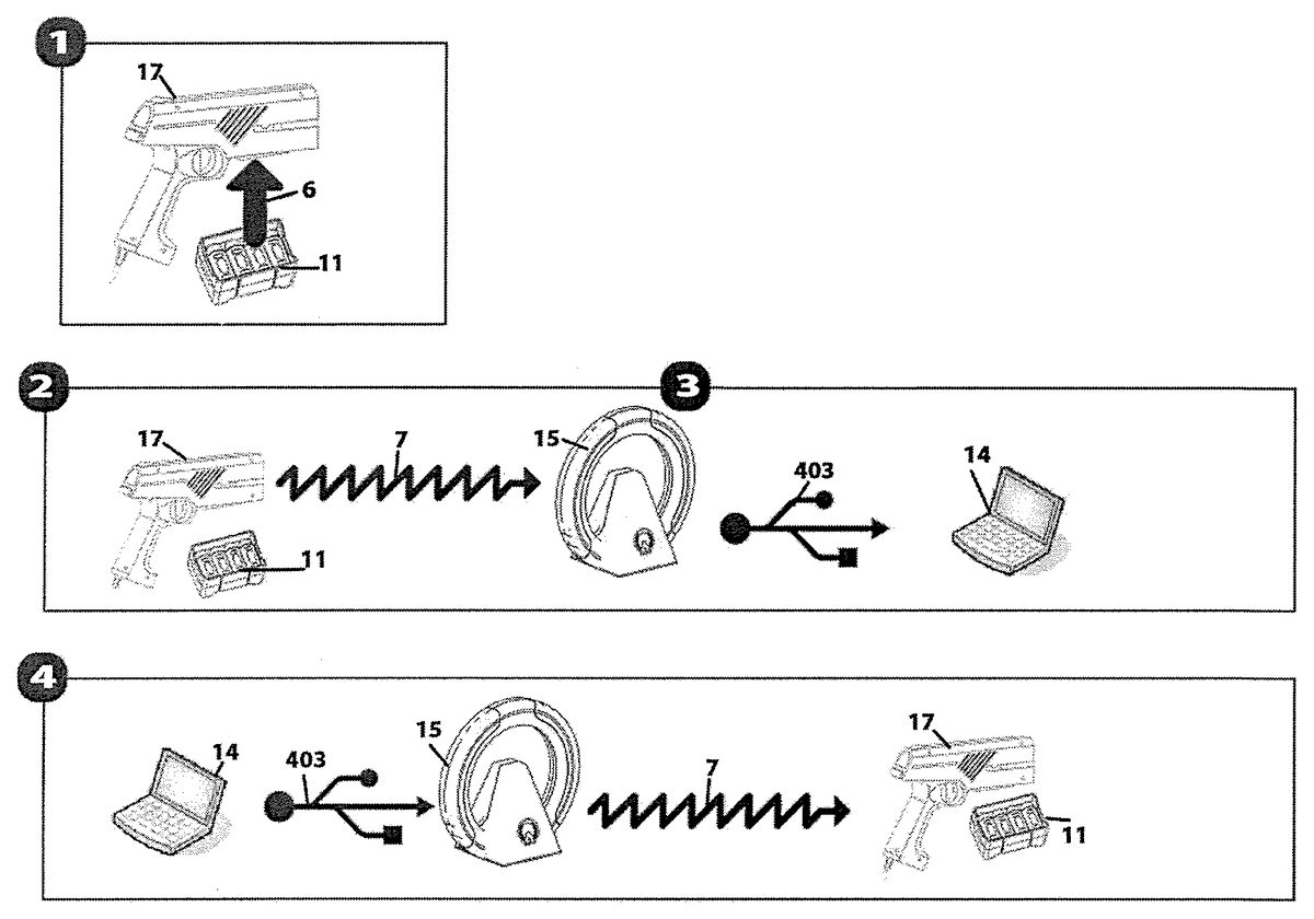
Exemplary embodiments of the game system1managed by the computer manager system14showing protocol or sequence steps are depicted inFIGS. 24 and 25.FIG. 24shows the interaction protocol between the transponder17and computer manager system14, relayed through the transceiver15, when the transponder17scans RFID-tagged goal-oriented objects such as an RFID Ammo box, life points, medical kits, flags, treasure chests, or other objects, during game play. Specifically, information in the form of wireless communications such as an RF signal7is transmitted from the transponder to the transceiver15, which translates the RE signal7into a command (information package sent via USB403to the computer manager14. In response, the computer manager14determines whether the transponder's scanning6falls within pre-determined guidelines, i.e., what type of RFID object is being scanned and whether that object is an allowable target for the transponder in question. Here the transponder17scans the ammunition box11a. The transponder's HUD120may indicate a message such as “scan pushed” to the player. The computer manager14sends a command (information package) via USB403to the transceiver15, which translates the data into an RE signal7, which is received by the transponder17, having a result. If the scanning action of the transponder17meets with success as determined by the computer manager system14, the transponder17may be provided with additional ammunition, or life points, or credit for the capture of a goal-oriented-object12. A change in status as a result of this activity is visible on the HUD120transponder17and a confirmation sound may be played.
FIG. 25depicts an exemplary interaction protocol and actions executed while playing a game where the protocol is a non-standard communication format and language that governs the transmitting and receiving of data. A protocol may define the packet structure of the data transmitted or the control commands that manage the session, or both. There are two main modes for interaction: the “manual mode” and the “automatic mode”.
In the manual mode, the transponder17itself does not make any decisions about what it knows or does not know relating to the game. Every input of information is sent from the transponder to the computer manager system14through the transceiver15with Radio Frequency communication7. Then the computer manager system, according to the current played game, sends back commands to the transponder17to trigger outputs.
In the automatic mode, depending on the current game, a small piece of code is sent to the computer manager system14at the beginning of the game. This mode is meant to reduce the load on the transponder in terms of battery consumption and Radio Frequency transmission. The piece of code that is sent to the computer manager is a program that tells the transponder17how to react to certain inputs, what data it should manage on its own and what information it is to send to the computer manager system through Radio Frequency. For example, in a death match game in which the player has pressed the trigger5, as shown in Box1, the transponder17, with the help of the sent code, checks if it has enough ammunition through the sequence of action depicted inFIG. 25Boxes2,3,4and5. Transponder17sends an RF signal7to the transceiver15which relays the command (information package) to the USB403linked Computer Manager14. The code running on the Computer manager system14analyzes whether or not the transponder has enough ammunition by checking the amount of ammunition the player has remaining. If the player has ammunition remaining, the Computer manager sends a command through USB403via the transceiver15and RF signal7to the transponder17allowing the gun to fire an infrared beam16, playa shot sound, display on the HUD the amount of ammunition left and then send just one Radio Frequency message to the computer manager system via the transceiver, as shown in Box2, saying, it has fired. If the player who shoots the beam hits another player as shown in Box6, the receptor system13of the shot player sends an electrical signal8to the transponder17which relays the command (information package) through an RF signal7, via the transceiver15and then through USB403to the computer manager system14telling by which player it has been hit. The computer manager system then subtracts a life point from the shot player, adjusts the score board by adding one hit point to the player that successfully shot the other player and sends a signal to the shot player's transponder17via the USB403and the transceiver15telling the shot player's transponder to vibrate132and subsequently displays one less life point on the HUD while playing a shot sound.
Interactive accessories that are made of plastic or other suitable material can also be deployed during game play to further enhance/vary the game play experience. Exemplary embodiments of interactive accessories include but are not limited to one or more of a bomb (FIG. 26), a grenade (FIG. 27), a set of multiple targets or a target system (FIG. 28), a zone protector or movement detector (FIG. 29), a can (FIG. 30) and/or a mini ammunition clip (FIG. 31).
FIG. 26illustrates an interactive accessory that is in the form of a beacon or time bomb which is comprised of Infrared emitters901, infrared receptors903, an LED902that flashes, an on/off switch to defuse/activate the bomb904, an accelerometer that is inside the device905along with an RFID tag, a battery pack906on the bottom of the device, an RF emitter, and a speaker907. The beacon or time bomb may be launched by players during gameplay. When the interactive accessory is activated, it sends a 360 degree infrared signal towards any player or group of players inside an area of a50mradius. Any player that is within range of the bomb is hit by the explosion and his or her receptor will react to the infrared signal sent from the bomb when hit, by displaying flashing LED light(s) that are coupled to the receptor. The beacon bomb could also be used in a game play where the object of the game is to defuse the bomb before it goes off. In this example, the beacon bomb could be hidden in a play environment and set to explode in a particular amount of time, the player or players would then have to find the beacon bomb and fire their transponder at it and/or switch the bomb off using either the transponder's RFID reader, an RF signal, or both to scan the bomb either through direct contact or from a distance of approximately 10 cm and/or switch the bomb off using a button904in order to defuse the bomb before it explodes. If they are too late, the beacon bomb sends out an RF signal relayed to the transceiver first and then to every players' transponders participating in the game.
FIG. 27depicts an interactive accessory that is in the form of a grenade which comprises an on/off switch912, a battery pack915powering the Infrared emitter910and an infrared sensor911. An RFID tag913may be placed inside of the grenade and could be scanned by the RFID scanner on the transponder either through direct contact or from a distance of approximately 10 cm. The grenade may be held by a patch of Velcro914on the player's harness.
FIG. 28illustrates an interactive accessory in the form of a target system comprising a master target920and3(three) slave targets921. Inside the master target there is a battery pack926, with a Radio Frequency emitter925. The master target also includes an on/off switch924, a chipset to control communication and functions929, and in the middle of the target an Infrared receptor922as well as an LED930that illuminates when the target is hit. The three slave targets are all connected by a wire928as well as to the master target920. There is a DC motor (not shown) that enables the targets to retract when tired upon. The target system could be used to practice alone and/or with other players for example as a stand alone target system coupled with a transponder, or it could be used during game play as part of the game play objectives.
FIG. 29illustrates an interactive accessory in the form of a zone protector or movement detector. It comprises of a Flashing LED933, various IR emitters941, infrared receptors934, a PIR (Infrared Red Passive receptor) detector935, A Radio Frequency emitter936, a chipset937, an on/off switch button939, and a battery pack940. It could be used as a zone protector during a game that consists of various zones. Each player's or team's zone could contain a goal-oriented object such as a flag or treasure or other valuable item that the player or team is trying to protect. The zone protector accessory could be used to monitor movement in the zone containing the valuable item so the player or players would be alerted on their transponder(s) to something moving in the protected area. It could also be used to defuse a bomb that could be deactivated when fired upon by the transponder.
FIG. 30depicts the an interactive accessory in the form of a Can which comprises infrared receptors945, an on/off switch946, a battery pack948and a DC motor947inside of the Can. It could be used during game play or as a stand alone device for target or shooting practice by one or more players.
FIG. 31depicts an interactive accessory in the form of a mini ammunition clip used to reload ammunition during game play. It comprises an RFID tag950inside of the mini ammunition clip that could be activated by the RFID scanner on the transponder either through direct contact or from a distance of approximately 10 cm. The mini ammunition clip also includes a velcro patch to position it on the player's harness334as seen onFIG. 13.
Games that can be played on the system include, but are not limited to, laser-tag, capture the flag, kill shot, death match, sword fighting, cops and robbers, cowboys and Indians, pirate games, war games or sports games, or games such as “Run forest”, “Alien Invasion”, “Cocoon”, “Call of tentacles”, “Old fashion Duel”, “Round of the Death”, “Sport Parts”, “Galactic Post Service”, “The Last Bunker”, “The Alien Virus”, “The General”, “In the Name of the Law”, “Rustlers”, “Fragmatch”, “Free Frag”, “Free for All”, “Team Frag”, “Liquidator”, “Last Man Standing”, “Vampire War”, “Space Mercenaries”, “Score Attack”, “Biathlon”, “Relay Race”, “Place and Tag”, “Triathlon”, “Simon Says”, “Lottery”, “Gold Rush”, “Hide and Seek”, that can be played indoors or outdoors button904in order to defuse
While embodiments of the disclosure have been described above, it will be apparent to one skilled in the art that various changes and modifications may be made. It should be understood that any of the foregoing configurations and specialized components may be interchangeably used with any of the systems of the preceding embodiments. Although illustrative embodiments of the present disclosure are described hereinabove, it will be evident to one skilled in the art that various changes and modifications may be made therein without departing from the disclosure. It is intended in the appended claims to cover all such changes and modifications that fall within the true spirit and scope of the disclosure.
Claims
- A game system comprising: a computer manager system adapted to manage gaming activities of one or more players;a transceiver in operative communication with the computer manager system;and one or more transponder/receptor units in operative communication with the transceiver, each transponder/receptor unit including a transponder and a receptor, each transponder/receptor unit including a display light indicating when a first player has been hit by second player firing a transponder/receiver unit, wherein a first transponder can communicate with a second transponder at a distance of at least about 80 meters without using the transceiver;wherein the transceiver is adapted to enable wireless communication between a transponder/receptor unit and the computer manager system over distances of at least about 250 meters in an indoor environment and at least about 750 meters in an outdoor environment.
- The game system of claim 1 wherein the computer manager system manages the gaming activities of the one or more players in real time.
- The game system of claim 2 wherein the computer manager system acts as one or more of: a master of the game and a referee of the game.
- The game system of claim 1 further comprising one or more goal-oriented objects, each goal-oriented object including a unique identifier and adapted for wireless communication with the one or more transponders.
- A method of playing a game for one or more players, said method comprising the steps of: sending a signal from a transceiver to a computer manager system coupled to said transceiver;receiving signals in a separate transponder/receptor unit used by each player;providing a visible indication when a first player has been hit by second player firing a transponder/receptor unit, wherein a first transponder/receptor unit can communicate with a second transponder/receptor unit at a distance of at least about 80 meters without using the transceiver;controlling the activity of said one or more players through the computer manager system by controlling the activity of each of said one or more players' transponder/receptor units during the game play, thereby serving as one of a master of the game and as a referee of the game;and wherein the computer manager system provides communication over distances of at least about 250 meters in an indoor environment and at least about 750 meters in an outdoor environment.
- The method of claim 5 wherein said transceiver is coupled to the computer manager system via a USB link.
- The method of claim 5 wherein the computer manager system is one of: a personal computer, a computer gaming platform, home game console, arcade game console, hand-held game device, internet gaming device, a cell phone, a television set, and a set top box.
- The method of claim 5 wherein the transceiver comprises one or more of: an LED infrared receptor, a Radio Frequency emitter consisting of a PCB antenna, a PCB with a control circuit and a USB wire.
- The method of claim 5 , wherein each transponder/receptor unit comprises: a transponder including an RF emitter, an infrared emitter and an RFID reader;and a receptor unit having one or more infrared receptor centers including one or more lights.
- The method of claim 5 , further comprising one or more goal-oriented objects adapted for wireless communication with the one or more transponders.
- The method of claim 10 wherein the one or more goal-oriented objects comprises a unique identifier.
Disclaimer: Data collected from the USPTO and may be malformed, incomplete, and/or otherwise inaccurate.