U.S. Pat. No. 8,550,915
GAME CONTROLLER WITH ADAPTER DUPLICATING CONTROL FUNCTIONS
AssigneeNintendo Co., Ltd.
Issue DateFebruary 16, 2011
Illustrative Figure
Abstract
A video game controller for a video game and a receptor assembly may include a controller core unit including a housing formed with a top, bottom and opposite sides, at least the top having a plurality of control buttons thereon; and a base portion provided with a first connector; a receptor having a shape substantially similar to a component appearing in the video game. The receptor may be a gun-shaped sub-unit with a barrel portion and a gripper portion with an open slot adapted to receive the core unit.
Description
DETAILED DESCRIPTION OF THE DRAWINGS FIG. 1is an external view of a game system1containing a game controller in accordance with a non-limiting exemplary embodiment of the present invention. InFIG. 1, the game system1includes a desktop game machine (hereafter described simply as a game machine)3connected via a connection cable to a display (hereafter described as a monitor)2equipped with speakers2a(such as found in a home-use television receiver), and a controller7which feeds operation data to the game machine3. Connected to (or built into) the game machine3is a reception unit6via a connection terminal. The reception unit6receives transmission data wirelessly sent from the controller7, and the controller7and the game machine3are connected via wireless communication. Removably inserted in the game machine3is an optical disk4which is an example of information storage medium used exchangeably for the game machine3. Installed on the top main face of the game machine3are a power on/off switch, a reset switch for game processing, and an open switch to open the top cover of the game machine. The top cover opens by a player pressing down the open switch, allowing insertion/removal of the optical disk4. Also, removably installed freely in the game machine3upon necessity is an external memory card5with built-in backup memory etc. which is a fixed storage for saved data etc. The game machine3executes a game program etc. stored on the optical disk4and displays the results on the monitor2as game images. The game machine3can also recreate a game state executed in the past using the saved data stored in the external memory card5and display the game images on the monitor2. Then, a player can enjoy the game progress by operating the controller7while watching the game images displayed on the monitor2. The controller7wirelessly transmits data from a built-in communication unit75(described hereafter in reference toFIG. 10) to the game machine3to which the reception unit6is ...
DETAILED DESCRIPTION OF THE DRAWINGS
FIG. 1is an external view of a game system1containing a game controller in accordance with a non-limiting exemplary embodiment of the present invention. InFIG. 1, the game system1includes a desktop game machine (hereafter described simply as a game machine)3connected via a connection cable to a display (hereafter described as a monitor)2equipped with speakers2a(such as found in a home-use television receiver), and a controller7which feeds operation data to the game machine3. Connected to (or built into) the game machine3is a reception unit6via a connection terminal. The reception unit6receives transmission data wirelessly sent from the controller7, and the controller7and the game machine3are connected via wireless communication. Removably inserted in the game machine3is an optical disk4which is an example of information storage medium used exchangeably for the game machine3. Installed on the top main face of the game machine3are a power on/off switch, a reset switch for game processing, and an open switch to open the top cover of the game machine. The top cover opens by a player pressing down the open switch, allowing insertion/removal of the optical disk4.
Also, removably installed freely in the game machine3upon necessity is an external memory card5with built-in backup memory etc. which is a fixed storage for saved data etc. The game machine3executes a game program etc. stored on the optical disk4and displays the results on the monitor2as game images. The game machine3can also recreate a game state executed in the past using the saved data stored in the external memory card5and display the game images on the monitor2. Then, a player can enjoy the game progress by operating the controller7while watching the game images displayed on the monitor2.
The controller7wirelessly transmits data from a built-in communication unit75(described hereafter in reference toFIG. 10) to the game machine3to which the reception unit6is connected, utilizing Bluetooth™ technology. The structure of the controller7is explained in detail hereafter, and generally comprises two control units (a core unit70(FIG. 3) and a sub-unit76described hereafter) mutually connected via a connector. In this exemplary embodiment, the control unit (sub-unit76inFIG. 3) has a shape imitating a gun as a whole. Also, installed in each unit is a control mechanism such as multiple control buttons, keys, and sticks. Furthermore, the other control unit (core unit70) is equipped with an imaging information operating unit for taking images viewed from the core unit70. As an example of an imaging target of this imaging information operating unit, two LED modules8L and8R (FIG. 12) which emit infrared light toward the front of the monitor2, are installed near the display screen of the monitor2.
The structure of the game machine3is explained hereafter, with reference to the functional block diagram ofFIG. 2.
InFIG. 2, the game machine3is equipped with a RISC CPU (Central Processing Unit)10, for example, which executes various kinds of programs. The CPU10executes a startup program stored in a boot ROM (not shown), and after performing initialization of memory such as a main memory13, executes a game program stored on the optical disk4, performing game processing etc. according to the game program. Connected to the CPU10via a memory controller11are a GPU (Graphics Processing Unit)12, the main memory13, a DSP (Digital Signal Processor)14, and an ARAM (Audio RAM)15. Also, connected to the memory controller11via specified buses are a controller I/F (interface)16, a video I/F17, an external memory I/F18, an audio I/F19, and a disk I/F21, to which the reception unit6, the monitor2, the external memory card5, the speakers2a, and a disk drive20are connected, respectively.
The CPU12performs image processing based on instructions of the CPU10, and comprises a semiconductor chip which performs necessary computation processes for displaying 3D graphics, for example. The CPU12performs image processing utilizing a memory exclusively for image processing (not shown) and a partial storage area of the main memory13. The GPU12uses these to create game image data and movie pictures to be displayed on the monitor2, and outputs them to the monitor via the memory controller11and the video I/F17as appropriate.
The main memory13is a storage area used by the CPU10, and stores game programs etc. necessary for processing by the CPU10. For example, the main memory13stores game programs and various kinds of data which are read out from the optical disk4by the CPU10. The game programs and various kinds of data stored by this main memory13are executed by the CPU10.
The DSP14processes sound data generated in the CPU10when a game program is executed, and connected to it is the ARAM15for storing its sound data etc. The ARAM15is used when the DSP14performs a specified processing step, (for example, storing game programs and sound data which were read ahead). The DSP14reads out sound data stored in the ARAM15and has them output to the speakers built into the monitor2via the memory controller11and the audio I/F19.
The memory controller11controls overall data transfer, to which the various kinds of I/Fs are connected. The controller I/F16consists of four controller I/Fs16a-16dfor example (not separately shown), and via their connectors it connects external equipment that can fit to the game machine3in a communicable manner. For example, the reception unit6fits with a connector and is connected with the game machine3via the controller I/F16. As stated above, the reception unit6receives transmission data from the controller7, and outputs said transmission data to the CPU10via the controller I/F16. Connected to the video I/F17is the monitor2. Connected to the external memory I/F18is the external memory card5, allowing access with backup memory etc., installed in the external memory card5. Connected to the audio I/F19are the speakers2abuilt into the monitor2, allowing the sound data read out from the ARAM15by the DSP14and sound data directly output from the disk drive20to be output through the speakers2a, Connected to the disk I/F21is the disk drive20which reads out data stored on the optical disk4placed in a specified read-out position, and outputs it to a bus of the game machine3and the audio I/F19.
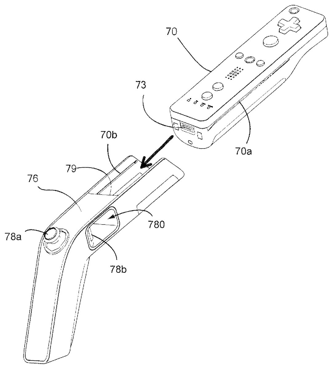
One non-limiting example of a controller7is explained hereafter, with reference toFIG. 3andFIG. 4.FIG. 3is an oblique view showing an external-view structure of the controller7.FIG. 4is an oblique view showing a state where the core unit70of the controller7is detached from the sub-unit76.
InFIG. 3, the controller7comprises the core unit70which is one example of a first control unit, and the sub-unit76which is one example of a second control unit to which the core unit70can be mounted in a freely detachable manner. Built into the core unit70are electronic components and multiple control switches necessary for functioning as a controller for the game machine3. The sub-unit76has a housing shaped to simulate a gun and thus includes a gun barrel portion76aand a gripper portion76b. Formed on the barrel portion of the housing is a laterally arranged penetrating hole or aperture)780which penetrates the side of the barrel, and installed inside the penetrating hole is a control switch member78bwhich can be pushed inwardly, in a direction toward the gripper portion76b. Also, an analog stick78awhich can point in 360-degree directions (i.e., a universal stick) is installed on a shoulder section where the barrel portion and the gripper portion are joined at an angle. In this embodiment, the core unit70mounted to the sub-unit76, functions as a controller for the game machine3.
InFIG. 4, a connector73is shown installed on the back end of the core unit70. The barrel portion76aof the housing of the sub-unit76incorporates an open slot or recess that is concave or U-shaped in section, enabling insertion of the core unit70into the sub-unit76. The concave section has at least a length which can support more than half the length of the core unit70. Also, installed at the rearward end of the concave section is a connector79(FIG. 8a) adapted to align with the connector73in the core unit. When the core unit70is inserted into the open slot or recess in the sub-unit, the connector79fits with the connector73. As a result, the core unit70and the sub-unit76become electrically connected. Also, grooves70aare installed on opposite sides of the core unit70, and elongated ribs or projections70bare provided in the concave section of the sub-unit76. By the grooves and ribs fitting with each other, the core unit70and the sub-unit76become physically connected, preventing their relative positions from deviating when mounted. Therefore, when mounting the core unit70in the sub-unit76, the core unit70is inserted to the concave section of the sub-unit76along the grooves70auntil the connector73and the connector79engage with each other, after which the core unit70and the sub-unit76will not separate from each other under normal operating conditions.
Core unit70is now explained hereafter with reference toFIG. 5andFIG. 6.FIG. 5is an oblique view of the core unit70from the upper rear.FIG. 6is an oblique view of the core unit70from the lower front.
The core unit70has a housing71formed by plastic molding for example. The housing71has a near-rectangular shape, elongated in the front-to-rear direction, and is sized so that it can be held with one hand of an adult or a child. The core unit70is a control unit which can also be used as a stand-alone controller or as the gun-type controller7, when attached to the sub-unit76.
A cross key72ais installed on the front center of the top face of the housing71. This cross key72ais a cross-type, four-direction, push switch, wherein control sections corresponding to four directions (front, rear, left, and right) are arranged on the projecting pieces of a cross at a 90-degree interval. By pressing one of the control sections of the cross key72a, one of the front, rear, left, and right directions is selected. For example, by the player controlling the cross key72a, he can instruct 4-8 moving directions of player characters appearing in a virtual game world and instruct the cursor moving direction.
While the cross key72ais a control unit which outputs a control signal according to the player's direction input operation, it may be a control unit of other shapes. For example, instead of a cross key72a, a compound switch may be installed which combines a push switch with four-direction control sections in a ring shape and a center switch installed in the center of the ring. Also, instead of the cross-key72a, a control unit may be installed which outputs a control signal according to the direction in which a universal stick projecting from the top face of the housing71is inclined. Furthermore, instead of the cross key72a, a control unit may be installed which outputs a control signal corresponding to the sliding direction of a disk-shape member which can move horizontally. Other alternatives to the switch key include a touch pad or plural switches, each of which indicates one of at least four directions (front, rear, left, and right) and outputs a control signal according to the switch pressed by the player.
Multiple control buttons72b-72gare installed rearwardly of the cross key72aon the top face of the housing71. The control buttons72b-72gconstitute a control unit which outputs a control signal assigned to each of the control buttons72b-72gby the player pressing the head of each button. For example, the control buttons72b-72dare assigned functions designated for “button No. 1,” “button No. 2,” and the “A button,” respectively. Also, the control buttons72e-72gare assigned functions designated for the “− button”, the “Home button,” and the “+ button”, respectively. Control buttons72b-72gare assigned their respective functions according to the game program executed by the game machine3. Because they have no direct relationship with the explanation of the present invention, a detailed explanation of the various button functions is not necessary.
In the arrangement example shown inFIG. 5, the control buttons72b-72dare installed along the central front-to-rear direction on the top face of the housing71. Also, the control buttons72e-72gare installed between the control buttons72band72dalong the left-to-right direction on the top face of the housing71. The control button72fhas its top face recessed in the top face of the housing71such that a player cannot inadvertently press down on the button. Also, a control button72his installed in the front side of the cross key72aon the top face of the housing71. The control button72his a power switch which remotely turns on/off the power of the game machine3main body. Control button72halso has its top face recessed in the top face of the housing71.
Multiple LEDs702are installed to the rear of the control button72con the top face of the housing71. Each controller7is assigned a controller classification (number) to distinguish it from other controllers7. For example, the LED702is used for notifying the player of the controller classification currently set to the controller7. Specifically, when transmission data is sent from the core unit70to the reception unit6, among the multiple LEDs702, the LED in the position corresponding to the controller classification lights up.
Also, sound release holes72jfor releasing sound form a speaker described hereafter (see speaker706inFIG. 7) are formed between the control button72band the control buttons72e-72gon the top face of the housing71.
A concave or recessed section72kis formed in the forward end of the housing bottom. As will become clear in the later description, this concave section is formed in a position permitting the player's index finger or middle finger to be located when the player holds the core unit70alone. A control button72iis installed on an inclined face behind said concave section. The control button72iis a control unit which functions as the “B button” for example, used as the trigger switch in shooting games or for operations to let the player object pay attention to a specified object. Attached behind the control button72iis the cover72mof a battery storage area in which to store batteries, for example.
Also, installed on the front end of the housing71is an imaging chip which constitutes a part of an imaging information operating unit74. The imaging information operating unit74is a system for analyzing image data taken by the core unit70to determine the location of a specified brightness and detect its position, size, etc. in the image, which has a sampling cycle up to about 200 frame/sec to allow tracing and analyzing even relatively high-speed motions of the core unit70. The detailed structure of this imaging information operating unit74is described further herein.
The internal structure of the core unit70is explained hereafter, with reference toFIG. 7(a) andFIG. 7(b).FIG. 7(a) is an oblique view where the upper enclosure portion (a part of the housing71) of the core unit70is removed.FIG. 7(b) is an oblique view showing the underside of the unit with the lower enclosure (a part of the housing71) removed.
InFIG. 7(a), the circuit board700is fixed inside the lower enclosure portion of the housing71, and installed on the top main surface of the circuit board are control buttons72a-72h, an acceleration sensor701, LEDs702, an antenna754, etc. These are connected to a microcomputer751via a wiring (not shown) formed on the circuit board700. Also, the core unit70functions as a wireless controller with a wireless module (not shown inFIG. 7but seeFIG. 10)and the antenna754. A quartz oscillator (not shown) is installed inside the housing71, generating the basic clock for the microcomputer described hereafter. Also, a speaker706and an amplifier708are installed on the top main face of the circuit board700. By the acceleration sensor701being installed not on center, but on the periphery of the circuit board700, according to the rotation around the length direction of the controller as an axis, acceleration containing the centrifugal force component can be detected in addition to changes in the direction of gravitational acceleration. Therefore, the controller rotation can be determined with a good sensitivity from the detected acceleration data by a specified calculation.
The imaging information operating unit74is installed on the front end of the bottom of the circuit board700. The imaging information operating unit74comprises an infrared filter741, a lens742, an imaging chip743, and an image processing circuit744sequentially from the front of the core unit70, each of which is also attached to the bottom of the circuit board700. Also attached to the bottom of the circuit board700are the connector73, a sound IC707and the microcomputer751. The sound IC707is connected with the microcomputer751and an amplifier708via wiring formed on the circuit board700etc. and outputs sound signals to the speaker706via the amplifier708according to the sound data sent from the game machine3. A vibrator704is also attached to the bottom face of the circuit board700. This vibrator704is a vibrating motor or a solenoid, for example, Because vibration is generated in the core unit70by the vibrator704, the vibration is transmitted to the player's hand, realizing a so-called vibration-enabled game. Because the vibrator704is placed relatively toward the front of the housing71, and with the housing71vibrating while the player is holding it, the vibration is easily felt by the player.
The sub-unit76is explained in detail hereafter with reference toFIG. 8andFIG. 9.FIG. 8(a) is a top view of the sub-unit76,FIG. 8(b) is a bottom view of the sub-unit76, andFIG. 8(c) is a left-side view of the sub-unit76.FIG. 9is an oblique view from the upper rear of the sub-unit76.
The sub-unit76has a housing77formed by plastic molding for example. The housing77approximately has a gun-type shape, wherein its left-to-right direction as the whole corresponds to the barrel direction when seen from the side (seeFIG. 8(b)). The housing77includes the barrel portion76aand the gripper portion76bformed at a specified angle to the barrel portion76a. Also, when the housing77is seen from the top side, the gripper portion is formed narrower than the barrel portion (seeFIGS. 8(a) and (b)). While in this embodiment the barrel portion76aand the gripper portion76bare formed as one continuous member, other embodiments may be constituted by connecting independent members at a specified angle. The gripper portion76bof the sub-unit76is sized to enable it to be held with one hand of an adult or a child. Although the sub-unit76has a shape imitating a gun even by itself, it is a control unit for enabling the entire functionality of the gun-type controller7by further mounting the core unit70on the barrel portion as described above.
Formed on the barrel portion76ais the concave or U-shaped section which supports the core unit70when the core unit70is inserted therein. Inside this concave section, the connector79is installed on the rear end, to which the connector73installed on the rear end of the core unit70can be connected. Also, the penetrating hole or aperture780which penetrates the side of the barrel portion76ais formed rearward of concave section but still within the barrel portion. Installed on the gripper-side face inside this penetrating hole780is the control switch78bwhich is a key top, an example of a first control switch member that can be pushed in a direction toward the gripper portion. While the control switch78bis constituted as described above, it may be any switch that can be operated with an index finger, such as a switch having a control member of a key or trigger shape that can be pushed in.
On the top face of the housing77, the stick78a, which is an example of the second control switch, is installed on a part connecting the barrel portion76ato the gripper portion76b. The stick78ais a universal stick member projecting from the top face of the housing77which can be inclined in any direction, and is a control unit which outputs a control signal according to the inclination direction and the inclination angle thereof. For example, an arbitrary direction or position can be specified by a player inclining the stick tip in an arbitrary direction of 360°, which can be utilized for instructing the moving direction of a player character appearing in a virtual game world or the moving direction a cursor. Also, the moving speed of a player character or a cursor can be specified according to the inclination angle. While the stick78ais a control unit which outputs a control signal according to said player's direction input operation, it may be a control unit of other shapes. For example, it may be a cross key similar to the cross key72a.
Next, the internal structure of the controller7is explained referring to the block diagram inFIG. 10.
InFIG. 10, the core unit70is equipped with a communication unit75, the acceleration sensor701, a control unit72and the imaging information operating unit74.
The imaging information operating unit74contains an infrared filter741, a lens742, an imaging chip743, and an image processing circuit744. The infrared filter741transmits only infrared ray out of incident light from the front of the core unit70. The lens742condenses infrared light transmitted by the infrared filter741and beams it to the imaging chip743. The imaging chip743is a solid-state imaging chip such as a CMOS sensor or a CCD for example, and images the infrared light condensed by the lens742. Therefore, the imaging chip743images only the infrared light transmitted by the infrared filter741to generate image data. The image data generated by the imaging chip743are processed in the image processing circuit744. Specifically, the image processing circuit744processes the image data obtained from the imaging chip743to detect high-brightness portions, and outputs processing result data showing the result of detecting their position coordinates and areas to the communication unit75. The imaging information operating unit74is fixed on the housing71of the core unit70, wherein its imaging direction can be changed by changing the direction of the housing71itself. As will become clear in the later description, based on the processing result data output from this imaging information operating unit74, signals according to the position or movement of the core unit70can be obtained.
It is preferred that the acceleration sensor701be a three-axis acceleration sensor. The three-axis acceleration sensor701detects linear accelerations in three directions, namely the up-down direction, the left-right direction, and the front-rear direction. Also, in other embodiments, a two-axis acceleration detection means may be used which detects linear accelerations only along the up-down and the left-right directions (or another pair of directions). For example, the three-axis or two-axis acceleration sensor701may be a type obtainable from Analog Devices, Inc. or ST Microelectronics N. V. It is preferred that the acceleration sensor701be a capacitance type (capacitance compound form) based on the MEM (Micro Electro Mechanical systems) technology with silicon fine processing. However, the three-axis or two-axis acceleration sensor701may be provided using an existing technology of acceleration detection means (piezoelectric type or piezoelectric resister type) or another appropriate technology developed in the future.
As is publicly known to one skilled in the art, the type of acceleration detection means used in the acceleration sensor701can detect only the acceleration along a line (linear acceleration) corresponding to each axis of the acceleration sensor.
Namely, the direct output from the acceleration sensor701is a signal indicating a linear acceleration (static or dynamic) along each of the two axes or three axes. Therefore, the acceleration sensor701cannot directly detect physical characteristics such as a motion along a non-linear path (circular for example), a rotation, a spin motion, an angular position, an inclination, a position, and an attitude.
However, it would be easily understood by one skilled in the art that further information on the core unit70can be estimated or computed by performing additional processing on acceleration signals output from the acceleration sensor701. For example, static acceleration (gravitational acceleration) is detected when the core unit70is still. The degree of gravitational acceleration acting on each axis component can be known from acceleration data output from the acceleration sensor701at this time. Because it is already known how the acceleration sensor701is attached to the core unit70, the relative inclination relationship between the gravity direction and the acceleration sensor701becomes known. Namely, if the acceleration sensor701is attached horizontally to the core unit70, the inclination of the object (core unit70) relative to the gravity vector can be estimated using the output from the acceleration sensor701. In this manner, the inclination, attitude, or position of the core unit70can be determined by combining the acceleration sensor701with the microcomputer751(or another processor). In the same way, when the core unit70equipped with the acceleration sensor701is moved with a user's hand by being dynamically accelerated as explained herein, by processing generated acceleration signals detected by the acceleration sensor701, various motions and/or positions of the core unit70can be computed or estimated. In another embodiment, the acceleration sensor701may be equipped with a built-in signal processing device or another kind of dedicated processing device for performing a desired processing on acceleration signals output from a built-in acceleration detection means before outputting a signal to the microcomputer751. For example, if the acceleration sensor detects static acceleration (gravitational acceleration for example), the built-in or dedicated processing device may convert the detected acceleration signal into the corresponding inclination angle. Data showing the acceleration detected by the acceleration sensor701are output to the communication unit75.
In another embodiment, instead of the acceleration sensor701a gyro sensor containing a rotor or an oscillator may be used. As an example of MEMO gyro sensor used in this embodiment, there is one obtainable from Analog Devices, Inc. Unlike the acceleration sensor701, the gyro sensor can directly detect rotation (or angular velocity) centering on at least one gyro element it contains. In this way, because a gyro sensor and an acceleration sensor are basically different, depending on which device is selected for each purpose, the processing performed on the output signals from these devices needs to be changed appropriately.
Specifically, if inclination and attitude are computed using a gyro sensor instead of an acceleration sensor, a large change is made. Namely, when using a gyro sensor, the inclination value is initialized in starting the detection. Then, the angular velocity data output from the gyro sensor are integrated. Next, the amount of change in inclination is computed from the initialized inclination value. In this case, the computed inclination corresponds to the angle. On the other hand, when computing inclination using an acceleration sensor, because inclination is computed by comparing the value of each axis component of gravitational acceleration with a specified reference, the computed inclination can be expressed in a vector, thus an absolute direction can be detected using the acceleration detection means without initialization. Also, while the nature of values computed as inclination is an angle if a gyro sensor is used, it is vector if an acceleration sensor is used. Therefore, if a gyro sensor is used instead of an acceleration sensor, a specified conversion needs to be performed on the inclination data considering the difference between the two devices. Because the properties of a gyroscope are publicly known to one skilled in the art as well as the basic difference between an acceleration detection means and a gyroscope, further details are omitted in this specification. While a gyro sensor has an advantage that it can directly detect rotation, in general an acceleration sensor has an advantage of having a better cost efficiency if applied to a controller such as the one used in this embodiment.
The communication unit75contains the microcomputer (micom)751, a memory752, a wireless module753, and the antenna754. The micom751controls the wireless module753which wirelessly transmits transmission data while utilizing the memory752as a storage area during processing.
Control signals (control data) from the control unit72, acceleration signals (acceleration data) from the acceleration sensor701, and processing result data from the imaging information operating unit74installed in the core unit70are output to the micom751. Also, control signals (control data) from the control unit78installed in the sub-unit76are output via the connectors73and79to the micom751. The micom751temporarily stores the input data (control data, acceleration data, and processing result data) as transmission data to be sent to the reception unit6. Here, while wireless transmission from the communication unit75to the reception unit6is performed at every specified cycle, because it is a general practice to perform game processing with 1/60 second as the unit, data need to be collected and sent with a shorter cycle. Specifically, the game processing unit is about 16.7 ms ( 1/60 second), and the transmission interval of the Bluetooth™ communication unit75is 5 ms. When transmission timing to the reception unit6is received, the micom751outputs the transmission data stored in the memory752as a series of control data, and outputs them to the wireless module753. Then the wireless module753modulates carrier wave of a specified frequency with these series of control data using the Bluetooth™ technology for example, and radiates the extremely low power radio signal from the antenna754. Namely, control data from the control unit72installed in the core unit70, control data from the control unit78installed in the sub-unit76, acceleration data from the acceleration sensor701, and processing result data from the imaging information operating unit74are modulated into extremely low power radio signals in the wireless module753and radiated from the core unit70. Then, extremely low power radio signals are received by the reception unit6of the game machine3, and through demodulating and decoding the extremely low power radio signals in the game machine3, a series of control data (control data, acceleration data, and processing result data) can be obtained. Then, the CPU10of the game machine3performs game processing based on the obtained control data and a game program. In structuring the communication unit using the Bluetooth™ technology, the communication unit75can be equipped with a function to receive transmission data wirelessly sent from other devices.
FIG. 11shows the controller7held with a right hand of the player. Also,FIG. 12illustrates a game operation performed using the controller7in association with the monitor2.
As shown inFIG. 11, in order for a player to play a game, the controller7(with the core unit70mounted on the sub-unit76) is held with one hand. Specifically, the gripper portion76bof the sub-unit76is held with the player's palm, middle finger, third finger, and little finger. In this state, the index finger is inserted into the penetrating hole or aperture780which is formed within a range operable with the index finger. Furthermore, the thumb is placed on the stick78a. In such a holding state, the player can support the barrel consisting of the barrel portion76aof the sub-unit76and the core unit70by putting them on the middle finger, and can firmly hold the controller7even while operating the control switch78bby sandwiching the barrel portion76abetween the index finger and the middle finger. Therefore, the controller7can be stably held even when the control key78bis operated during a game operation.
Also, the index finger is placed inside the barrel portion, even if the thumb is placed on the stick78ainstalled on the top face of the housing77for an operation, and because the distance between those fingers becomes smaller compared with that for a normal gun shape, the movable range for the fingers becomes wider, making the operation easier.
Furthermore, as shown with an alternate long and short dash line inFIG. 11, because the index finger is placed on a line or axis passing inside the barrel portion, it is easy to recognize the direction in which the controller is pointing from the feeling of the hand, even without aligning the line of view to the barrel position as in an actual gun. Although in an actual gun it is structurally impossible to install a trigger inside the barrel portion, because the invention of the present application is simply a game controller that imitates a gun, a switch imitating a trigger can be installed inside the barrel, making its operation easier.
The player holds the controller7so that the front (incident side of light imaged by the imaging information operating unit74) of the core unit70points to the monitor2. At the same time, the two LED modules8L, and8R installed near the display screen of the monitor2, each output infrared light toward the front of the monitor2.
By a player holding the controller7so that it points to the monitor2, infrared light beams output by the two LED modules81and8R enter the imaging information operating unit74. Then, images of the incident infrared light beams are taken by the imaging chip743via the infrared filter741and the lens742, and the taken images are processed by the image processing circuit744. Here, in the imaging information operating unit74, position and area information of the LED modules81and8R is obtained by detecting infrared component output from the LED modules81and8R. Specifically, the imaging information operating unit74analyzes image data taken by the imaging chip743, excludes images that cannot be from infrared light from the LED modules81and8R based on the area information, and determines positions with high brightness and the positions of the LED modules8L and8R. Then, the imaging information operating unit74obtains their determined position coordinates and center of gravity coordinates and output them as the processing result data.
Shown inFIG. 13is an example of images taken by the imaging chip743. InFIG. 13, an area A1shows the range of an image being taken, relative to which image the xy coordinates are set. By pointing the front of the controller7to the monitor2, images8L′ and BR′ of the LED modules81and8R are taken, and the position coordinates or the center of gravity coordinates of8L′ and8R′ are expressed in the xy coordinates and are output. By sending this kind of processing result data to the game machine3, the game machine3can obtain control signals related to the movement, attitude, and position of the imaging information operating unit74, namely the core unit70, relative to the LED modules81, and8R based on the position coordinates and center of gravity coordinates. Specifically, because the positions of high-brightness points in an image sent from the communication unit75changes by the core unit70being moved, by performing direction input and coordinate input corresponding to the position change of the high-brightness points, direction input and coordinate input along the moving direction of the core unit70can be performed.
In this way, by imaging markers (infrared light beams from two LED modules8L and8R in the embodiment) installed in a fixed manner by the imaging information operating unit74of the core unit70, control data related to the motion, attitude, and position of the core unit70become available for game processing in the game machine3, and control input becomes more intuitive than using control buttons and control keys pushing buttons. Also, as stated above, because the markers are installed near the display screen of the monitor2, positions relative to the markers can also be easily converted into the motion, attitude, and position of the core unit70relative to the display screen of the monitor. Namely, control data by the motion, attitude, and position of the core unit70can be used as a control input directly acting on the display screen of the monitor2.
As stated above, while explanation was given on using the gun-type controller7combining the core unit70and the sub-unit76, the core unit70can be also used as a controller7alone without mounting the sub-unit76. In that case, although the controller7would not imitate a gun, the same kind of controls as in the case of combining them can be performed with a simple controller.FIG. 14andFIG. 15, illustrate a state where a player holds only the core unit70with one hand.FIG. 14shows the player holding the core unit70with the right hand viewed from the left side face of the core unit70.FIG. 15shows the player holding the core unit70with the right hand viewed from the front of the core unit70.
As shown inFIG. 14andFIG. 15, the core unit70is sized to enable it to be held with one hand of an adult or a child. Then, when the player's thumb is placed on the top face (near the cross key72afor example) of the core unit70, and the player's index finger is placed on the concave section (near the control button72ifor example) on the bottom face of the core unit70, a light incident port of the imaging information operating unit74installed on the front of the core unit70becomes exposed in a direction forward or to the front of the player. Needless to say, the core unit70can be held in the player's left hand in the same way.
In this way, the player can easily operate the control unit72including the cross key72aand the control button72iwhile holding it with one hand. Furthermore, when the player holds the core unit70with one hand, because the light incident port of the imaging information operating unit74installed on the front of the core unit70becomes exposed, infrared light beams from said two LED modules8L and8R can be easily taken in through the light incident port. In other words, the player can hold the core unit70with one hand without obstructing any function of the imaging information operating unit74. Moreover, the core unit70can be further equipped with a control input wherein the player's hand movement directly acts on the display screen by the player moving the hand holding the core unit70relative to the display screen.
As stated above, even with the core unit70alone, a pointing operation can be performed using the imaging information operating unit74, wherein it becomes possible to perform the same operations as in the case of the gun-type controller7combining the core unit70and sub-unit76by using the control button72iin place of the control switch78b, and the cross key72ain place of the stick78afor example. Therefore, the player can select whether the sub-unit76should be mounted to the core unit70according to the necessity.
Explained now is an example of operating a game using the gun-type controller in a shooting game.FIG. 16is a figure showing a game image example displayed on the monitor2when the game machine3executes the shooting game.
InFIG. 16, a part of a 3-D virtual game space S is displayed on the display screen of the monitor2. Then, displayed on the display screen as a game object which acts according to the operation of the controller7, is a part of a player character P and a part of a gun G owned by the player character P. Also, in the virtual game space S displayed on the display screen, a field of view which becomes the front of the player character S is expressed, and an enemy character E is displayed as a shooting target. A sight showing the position for the player character P to shoot with the gun G is displayed as a sight cursor T on the display screen.
In such a shooting game where the game image is displayed on the monitor2, the player proceeds in the game by operating the controller7with one hand. For example, by the player inclining the stick78a(seeFIG. 8andFIG. 9) installed on the sub-unit76, the player character P moves in the virtual game space S according to that inclination direction. Also, by the player moving the hand holding the controller7relative to the display screen, the sight cursor T moves according to the motion, attitude, and position of the core unit70relative to the monitor7(LED modules8L and8R). Then, by the player pressing down the control key78b(seeFIG. 8andFIG. 9), the gun G owned by the player character P shoots toward the sight cursor T.
Because the player can use the whole controller7as if it were a gun in a shooting game as he uses the stick78ainstalled on the sub-unit76for instructing the movement of the player character P, excitement of the shooting game further increases.
In the second example, similar to said first example, by a player inclining the stick78ainstalled on the sub-unit76, a player character P moves in a virtual game space S according to that inclination direction. Then, by the player moving the hand holding the core unit70relative to the display screen, the gazing point of a virtual camera moves according to the position of the core unit70relative to the monitor2(LED modules8L and8R). By such operations, the player can gaze a position in the virtual game space S to which the core unit70is pointed, using the stick78afor instructing the movement of the player character P.
While the controller7and the game machine3have been described as connected through wireless communication, the controller7and the game machine3may also be electrically connected via a cable. In this case, the cable connected to the core unit70is connected to a connection terminal of the game machine3.
Also, while the communication unit75was installed only in the core unit70among the core unit70and the sub-unit76structuring the controller7, a communication unit which wirelessly transmits transmission data to the reception unit6may be installed in the sub-unit76. Also, the communication unit may be installed in each of the core unit70and the sub-unit76. For example, communication units installed in the core unit70and the sub-unit76may each wirelessly transmit transmission data to the reception unit6, or transmission data may be wirelessly sent from the communication unit of the sub-unit76to the core unit70and be received by the communication unit75of the core unit70, and then the communication unit75of the core unit70may wirelessly transmit the transmission data of the core unit70to the reception unit6together with the transmission data of the sub-unit76.
Also, while the explanation was given using the reception unit6connected to a connection terminal of the game machine3as a reception means to receive transmission data wirelessly sent from the controller7, the reception means may be comprised of a reception module installed inside the game machine3main body. In this case, the transmission data received by the reception module are output to the CPU10via a specified bus.
Also, while an explanation was given by having the core unit70contain the imaging information operating unit74as an example of a detection unit which outputs signals (processing result data) that change according to the movement of the core unit70main body, it may be another mechanism. For example, while the core unit70contains the acceleration sensor701as stated above, a gyro sensor may be used in place of the acceleration sensor701, and using these detection signals, they can be used as a detection unit which outputs signals that change according to the movement of the core unit70main body. In this case, the imaging information operating unit74built in the core unit70may be removed, or both the sensor and the imaging information operating unit may be combined in the structure.
Also, while explained was a form wherein image data taken by the imaging chip743are analyzed to obtain the position coordinates of infrared light images from the LED modules8L and8R, and they are generated as processing result data in the core unit70and sent to the game machine3, data in another processing stage may be sent from the core unit70to the game machine3. For example, image data taken by the imaging chip743may be sent from the core unit70to the game machine3, and the analysis process may be performed in the CPU10to obtain the processing result data. In this case, the image processing circuit744installed in the core unit70becomes unnecessary. Also, data in the middle of analysis in the image data may be sent from the core unit70to the game machine3. For example, data indicating brightness, position, area, etc. obtained from the image data may be sent from the core unit70to the game machine3, and the remaining analysis process may be performed in the CPU10to obtain the processing result data.
Also, while in the above explanation, infrared light beams from two LED modules8L and8R were made imaging targets of the imaging information operating unit74of the core unit70, other objects may be made the imaging targets. For example, one or three or more LED modules may be placed near the monitor2, and infrared light beams from those LED modules may be made the imaging targets of the imaging information operating unit74. Also, the display screen itself of the monitor2or other luminous bodies (such as room lights) may be made the imaging targets of the imaging information operating unit74. If the position of the core unit70relative to the display screen is computed based on the position relationship between the imaging targets and the display screen of the monitor2, various luminous bodies can be used as the imaging targets of the imaging information operating unit74.
Also, shapes of said core unit70and the sub-unit76, and shapes, numbers, installation position, etc. of the control units72and78installed there are merely an example, and needless to say, the present invention can be realized with other shapes, numbers, and installation positions. Also, the game controller of the present invention was explained listing as an example the controller7with the sub-unit76and the core unit70connected. However, the existence of the core unit70is not always necessary, and said sub-unit76itself was also shown. Also, if the hardware shown inFIG. 10is mounted on the sub-unit76, it can also be utilized as a complete replacement for the controller7.
In this manner, the controller of the present invention made it possible by installing the control switch78bin a penetrating hole or aperture installed inside the barrel to keep holding the controller stably even during a game wherein the gun-type controller7is operated as if it were a gun. Also, by installing the control switch78bin the penetrating hole installed inside the barrel, even when the stick78ainstalled on the top face of the housing77is operated simultaneously with the control switch78b, there is no need to extend one's fingers to operate them, having an advantage of easy operation. Furthermore, because an index finger is placed on a line passing inside the barrel, the direction pointed by the controller7can be easily recognized through feeling of the hand without aligning the line of sight to the barrel position as in an actual gun.
FIGS. 17-32illustrate further examples of receptor devices or sub-units that can be employed to receive or hold core units70, and it will be appreciated that the various sub-units may or may not include additional control units such as those shown at72and78described hereinabove. In other words, the sub-units may interface with the core unit as described above, or the subunit may simply hold the core unit with no electronic interface. For example, for some games, button72ion the core unit70may not be required at all, or its function may be carried out by another button as the sub-unit.
Moreover, in some instances, the imaging information unit74may not be required (no pointing operations necessary), but the two or three axis acceleration sensor701will nevertheless detect movements of the core unit (and hence the sub-unit or receptor) that can be transferred to a game character on a monitor.
More specifically,FIG. 17illustrates a core unit70received within the hub of a video game steering unit761. The core unit70rotates with the wheel762and stick763on the unit761may correspond to stick78adescribed above.
FIG. 18illustrates the core unit70received within a recess formed in a video game joystick type device764.
FIG. 19illustrates a core unit70received within the handle portion of another gun type video game controller765.
FIG. 20illustrates a core unit70attached along a top of a pair of wearable goggles766. In this application, the imaging information unit74is not required.
FIG. 21illustrates a core unit70attached along one side of a pair of wearable goggles767in an arrangement where the imaging information unit74may be utilized if desired.
FIG. 22illustrates a core unit70secured to one side of a wearable racing or other helmet768, otherwise similarly arranged as inFIG. 21.
FIG. 23adiscloses a core unit70received within a recess formed in a simulated baseball bat769. To facilitate insertion of the core unit70, the simulated baseball bat is divided into two components, including a handle portion770that may be threadably secured to the barrel portion771.
FIG. 23billustrates an alternative arrangement wherein the handle portion772of a bat incorporates the electronics and control buttons of a core unit70, with the control buttons accessible on the surface of the handle.
FIG. 24illustrates a core unit70received in the side wall of a rocking seat773.
FIG. 25illustrates a core unit70attached to the wrist of a user by means of a strap774.
FIG. 26illustrates a core unit70attached to a real or simulated fishing rod775, the core unit70received within a hollow cylinder of a real or simulated reel component776of the rod.
FIG. 27illustrates a core unit70received within a stuffed toy animal777.
FIG. 28illustrates a core unit70forming the handle portion of a real or simulated golf club778.
FIG. 29illustrates a core unit70attached to a bicycle779and, more specifically, the core unit70is received within an otherwise hollow pedal780.
FIG. 30illustrates a core unit70attached to a skateboard781, and more specifically, within a hollowed center hub portion782of a skateboard wheel783.
FIGS. 31aand31billustrate a core unit70received within a hollow handle portion of a tennis or badminton racquet784. More specifically, an open slot785is formed in the handle portion of the racket, with opposed flanges786adapted to be received within aligned slots70aformed along opposite sides of the core unit70.
FIG. 32illustrates, in a generic sense, a receiving or docking device (or sub-unit)787formed with a recess788on its top side in which is seated a male connector789adapted to be received in the female connector73in the base of the core unit70.
FIG. 33illustrates a slightly modified arrangement where the core unit70is connected to a sub-unit790and wherein the male connector791projects from the top surface of the device and, in order to stabilize the attachment, projecting tabs792on either side of the connector791are utilized in conjunction with mating recesses or holes793formed in the base of the core unit70, on either side of the female connector73.
From the above, it will be appreciated that the core unit70may be detachably secured in any number of ways to any number of receptor devices or sub-units that may or may not have additional control units or buttons incorporated therein, and where some or all of the functionality of the core unit70are utilized. The above examples of the various receptors are intended to be illustrative only, and the invention is no way limited to any specifically shaped or configured receptor. It will be appreciated that the receptor device may or may not be at least peripherally related to the subject matter of the video game being played.
While the technology herein has been described in connection with exemplary illustrative non-limiting implementations, the invention is not to be limited by the disclosure. The invention is intended to be defined by the claims and to cover all corresponding and equivalent arrangements whether or not specifically disclosed herein.
Claims
- A video game controller and receptor assembly comprising: an elongated, substantially rectangular electronic video game controller core unit for operating an electronic game comprising a housing having a top, bottom, opposite sides, a forward end and a rearward end, said top having a plurality of control buttons including a crosskey thereon and said bottom having an inclined face with a trigger switch adjacent said forward end and projecting from said inclined face;and a receptor unit shaped to simulate a device held or worn by a character in the electronic game, said receptor formed with a forwardly-facing open-topped recess with sides and a bottom defining a shape substantially similar to at least a portion of the bottom and opposite sides of the video game controller core unit received in said recess, such that said forward end and said trigger switch project forwardly beyond said receptor unit.
- The video game controller and receptor assembly of claim 1 wherein said rearward end of said video game controller core unit is provided with a first connector and wherein said recess includes a rear wall provided with a second connector coupled to said first connector to thereby establish an electrical connection between the core unit and the receptor unit.
- The video game controller and receptor assembly of claim 1 wherein said housing is formed with slots on said opposite sides, and wherein said recess is formed with aligned ribs adapted to be received within said slots.
- The video game controller and receptor assembly of claim 2 wherein said first connector is a male connector and said second connector is a female connector.
- The video game controller and receptor assembly of claim 2 wherein said receptor unit is provided with at least one switch that performs a function of one of said control buttons or said trigger switch.
- A video game controller and receptor assembly comprising: an elongated, substantially rectangular electronic video game controller core unit for operating an electronic game comprising a housing having a top, bottom, opposite sides, a forward end and a rearward end, said top having a plurality of control buttons including a crosskey thereon and said bottom having an inclined face with a trigger switch adjacent said forward end and projecting from said inclined face;a receptor unit shaped to simulate a device held or worn by a character in the electronic game, said receptor formed with a forwardly-facing open-topped recess with sides and a bottom defining a shape substantially similar to at least a portion of the bottom and opposite sides of the video game controller core unit received in said recess;and wherein said receptor unit is provided with two switches that perform respective functions of said trigger switch and one of said control buttons.
- The video game controller and receptor assembly of claim 6 wherein said receptor unit comprises a second controller in the shape of a steering wheel or a joystick.
- The video game controller and receptor assembly of claim 6 wherein said receptor unit comprises a game racquet.
- The video game controller and receptor assembly of claim 6 wherein said receptor unit comprises a ball bat.
- The video game controller and receptor assembly of claim 6 wherein said receptor unit comprises a chair.
- The video game controller and receptor assembly of claim 6 wherein said receptor unit comprises a fishing rod assembly.
- The video game controller and receptor assembly of claim 6 wherein said receptor unit comprises a golf club.
- The video game controller and receptor assembly of claim 6 wherein said receptor unit comprises a toy figure.
- The video game controller and receptor assembly of claim 6 wherein said receptor unit comprises a wheeled toy.
- A receptor for an electronic video game controller comprising: a receptor housing including side walls extending along an elongated forward portion and a rearward gripper portion;a substantially U-shaped slot formed in said elongated forward portion in part by said side walls, said substantially U-shaped slot open at a forward aiming end of said forward portion of said receptor housing and adapted to receive an electronic video game controller such that, in use, said forward aiming end of said receptor housing and a forward end of the electronic video game controller can be aimed at a target display;said substantially U-shaped slot having a length sufficient to support a portion of the electronic video game controller substantially co-axially with said elongated forward portion of said receptor housing;a first connector at a rearward, closed end of said substantially U-shaped slot adapted to align with and engage a mating second connector on a rearward end of the electronic video game controller to thereby enable electrical connection between said receptor housing and the electronic video game controller;a trigger switch located within said receptor housing, substantially axially aligned with said substantially U-shaped slot, rearwardly of said first connector, said trigger switch accessible through openings in said sidewalls;and a universal stick on said receptor housing at in interface between said elongated portion and said gripper portion.
- The receptor of claim 15 wherein said gripper portion extends angularly from said elongated portion.
- The receptor of claim 15 in combination with the electronic video game controller, said electronic video game controller having a controller housing including a top face, a bottom, opposite sides, forward and rearward ends, a trigger button projecting from said bottom and a universal button on said top face;wherein said bottom and said opposite sides of said portion of said controller housing are supported in said U-shaped slot in said receptor housing and have a shape complementary to said U-shaped slot;said forward end of said controller housing, including said trigger button projecting from said forward aiming end of said receptor housing.
- The receptor of claim 17 wherein, in use, when said receptor and said electronic video game controller are electrically connected, said trigger switch and said universal stick perform functions of said trigger button and said universal button, respectively.
- A receptor for an electronic video game controller comprising: a receptor housing including substantially parallel side walls extending along an elongated forward portion and a rearward gripper portion;a substantially U-shaped slot formed in said elongated forward portion in part by said substantially parallel side walls, said substantially U-shaped slot open at a forward aiming end of said forward portion of said receptor housing remote from said rearward gripper portion and adapted to receive an electronic video game controller such that, in use, said forward aiming end of said receptor housing and a forward end of the electronic video game controller can be aimed at a target display;a first connector adapted to align with and engage a mating second connector on the electronic video game controller to thereby establish electrical connection between said receptor housing and the electronic video game controller;and a trigger switch located within said elongated forward portion between said substantially parallel side walls and rearwardly of said substantially U-shaped slot, said trigger switch substantially axially aligned with said substantially U-shaped slot and accessible through openings in said substantially parallel sidewalls.
- The receptor of claim 19 wherein said rearward gripper portion extends angularly downwardly and away from said elongated forward portion.
- The receptor of claim 19 further comprising a universal stick at in interface between said elongated forward portion and said rearward gripper portion.
- The receptor of claim 19 wherein said first connector is located at a rearward, closed end of said substantially U-shaped slot.
Disclaimer: Data collected from the USPTO and may be malformed, incomplete, and/or otherwise inaccurate.