U.S. Pat. No. 8,540,572
VIDEO GAME CONTROLLER FOR MULTIPLE USERS
Issue DateJuly 12, 2012
Illustrative Figure
Abstract
The present invention provides a video game controller and apparatus that may be used by two or more players. The users physically manipulate the control device cooperatively to the kinesthetic feedback of the other player(s) to control the events of the video game. By working together through orientation of the controller, the players can jointly move the video game object on the screen and/or govern the play of the game.
Description
DETAILED DESCRIPTION OF THE INVENTION The present invention relates to a video game controller for cooperative use by multiple users. The controller is sized to be operated by two or more users. During play, the users in combination must physically manipulate the control device, responding cooperatively to the kinesthetic feedback of the other player(s) to control the events in the video game or simulation. The invention is intended to serve several purposes, including encouraging teamwork by two or more players to achieve a common goal. The invention also allows people that would otherwise be unable to physically handle or manipulate a video game controller alone to play with one or more other players who, as a team, are able to manipulate the controller and play the game. The invention may include a single controller that is manipulated by all players in the form of a bar, rod, or other controller shaped in a manner that can be easily held, pushed, or otherwise maneuvered by two or more people. For instance, the controller can by two players in one or both of each player's hands. Or, the controller may be a ball or other device that can be pushed by two or more players on the floor or large surface. The latter type of device is especially advantageous for one or more players that have difficulty holding a conventional controller, such as persons that are wheelchair-bound. While not intending to be limiting,FIGS. 1-4illustrate various possible embodiments of the controller of the invention. For instance,FIG. 1shows one potential embodiment of the controller in the shape of a T-bar10whereby up to three users can each hold onto one of the bars12,14and/or16. The T-Bar includes an X axis18and Y axis19for sensing the orientation of the controller10in horizontal and vertical planes, respectively. FIGS. 2-4show similar ...
DETAILED DESCRIPTION OF THE INVENTION
The present invention relates to a video game controller for cooperative use by multiple users. The controller is sized to be operated by two or more users. During play, the users in combination must physically manipulate the control device, responding cooperatively to the kinesthetic feedback of the other player(s) to control the events in the video game or simulation. The invention is intended to serve several purposes, including encouraging teamwork by two or more players to achieve a common goal. The invention also allows people that would otherwise be unable to physically handle or manipulate a video game controller alone to play with one or more other players who, as a team, are able to manipulate the controller and play the game.
The invention may include a single controller that is manipulated by all players in the form of a bar, rod, or other controller shaped in a manner that can be easily held, pushed, or otherwise maneuvered by two or more people. For instance, the controller can by two players in one or both of each player's hands. Or, the controller may be a ball or other device that can be pushed by two or more players on the floor or large surface. The latter type of device is especially advantageous for one or more players that have difficulty holding a conventional controller, such as persons that are wheelchair-bound.
While not intending to be limiting,FIGS. 1-4illustrate various possible embodiments of the controller of the invention. For instance,FIG. 1shows one potential embodiment of the controller in the shape of a T-bar10whereby up to three users can each hold onto one of the bars12,14and/or16. The T-Bar includes an X axis18and Y axis19for sensing the orientation of the controller10in horizontal and vertical planes, respectively.
FIGS. 2-4show similar alternative embodiments of the controller20,30, and40, respectively, whereby the controller is either oriented on axis (FIGS. 1 and 2) or off axis (FIGS. 2 and 3). The controllers ofFIGS. 2-4also include an X axis28,38, and48, respectively, and a Y axis29,39, and49, respectively.
FIG. 5further shows yet another possible embodiment whereby the outer portion of the controller50is in the shape of a ball that can be jointly manipulated by two or more players52and54, whereby a T-Bar device56having an X axis58and Y axis59is provided inside the ball50for sensing the orientation of the controller. A weight57is further included inside the ball50to help keep the ball50centered during play.
The controller may also, for instance, be attached to the players' body (or body parts) such as through the use of connected waist bands, belts, headbands, a belt that surrounds and encompasses the users, ankle bands, leg straps, etc. so that the sensory collaboration of physical movement of the players will simultaneously influence the events in the game, as shown inFIG. 6.
A prior art controller that is designed for only one person play for multiple person play may also be adapted for use in accordance with the invention. For instance, a regular controller may be inserted within or fitted inside a larger device to increase the gripping surface of the controller, thus allowing the controller to be more easily held by two or more players for simultaneous game play. The enlarging device may be made in a variety of colors, materials, and/or designs that are aesthetically pleasing to the players, and may further include features to improve the ability of players to hold onto the controller, such as surface ribbing or bumps, or even slots in which the players can rest their fingers.
For physically challenged individuals, the adapting device may be designed with accommodating features for weak or less functional fingers to help secure their fingers or hands to the controller through the device, such as with the inclusion of a glove, pocket, or even rings through which the player(s) can insert his/her fingers. These same types of features may further be included in the design of the controller made in accordance with the invention. The device may also optionally include cushioning or other features that may the device and controller more comfortable to hold. Such features are well known and understood by persons skilled in the art.
The adapting device should be designed in a manner for comfort and/or style while also allowing the users to control the game object through motion of the controller. For instance, if the controller employs buttons or a keypad, the adapting device must also allow the players access to the control buttons or keypad to control the game object. If the controller employs laser tracking, such as a Wii controller, then the adapting device must include an opening for the laser from the controller to communicate with the console or CPU.
In still another embodiment as shown inFIG. 6, the adapting device60may simply be a belt or strap that is wrapped around or otherwise attaches to the controller62and then also to at least one portion of each of the players64and66so that the movements of the players64and66control the movements of the controller62and likewise the game object (not shown). In this regard, the device may be a “fanny pack” type device with a pocket or compartment in which the controller may be inserted while also including a belt for wrapping the device around the players.
With reference toFIG. 7, the invention should include conventional video game features that are well known in the art to enable the users through the controller (Multiplayer Control Unit (MCU))70to control a game object (not shown) on a video display unit70, such as a television or computer monitor. In this regard, the controller70may include a conventional housing72in which at least one accelerometer74is mounted and configured to measure the movement and orientation of the controller70along each of one (x), two (x and y) or three (x, y, and z) axe(s) over time. The accelerometer74is preferably a three-axis linear accelerometer that detects linear acceleration along each of an X axis, Y axis and Z axis. Alternatively, a one-axis or two-axis linear accelerometer may be used in another embodiment depending on the type of control signals desired. Any suitable accelerometer technology now existing or later developed may be used to provide the accelerometer74.
The accelerometer74communicates with a microprocessor76. The microprocessor76communicates with a port78which in turn is configured to communicate with a CPU90by wire (not shown) or via a wireless receiver79. The CPU90produces a video display signal which is used with the video display device100to display the video game. The CPU90may be part of a game console of any type, including Wii, Playstation, Xbox, etc., or part of a computer or lap top.
As already noted, the controller of the present invention includes a housing molded of plastic or metal, for example. The housing has a holding portion and is of a size capable of being held by at least one hand each of two or more adults and/or children. The shape of the housing is not limited to a rectangular shape but may also be in the shape of an oval, circle, rod, a t-bar (as shown inFIGS. 1 and 2), a cross (as shown inFIGS. 3 and 4), a ball (as shown inFIG. 5), or the like. Likewise, its cross-section shape is not limited to a rectangle and may be a circle or other polygon.
The adapting device of the invention is also not limited in terms of size or shape so long as it is also of a size capable of being held by at least one hand each of two or more adults and/or children, and may therefore also be of any polygonal shape or may also be a t-bar, for example. The adapting device must also include means by which to house or fasten the prior art controller within or on itself, such as by a strap, belt, or casing in which the controller sits in or is housed. As also already noted, the adapting device may simply consist of a strap or belt that attaches to the controller and also to the players so that the joint motion of the players causes the controller to move likewise.
The housing may optionally include a power switch to remotely turn on or off an electric power source to a game machine by a remote operation. For wireless use, a battery cover is conventionally detachably attached to the lower housing to form a holding portion in which batteries are stored. Thus, the controller may operate with a battery as a power source or by wired connection to the console.
As noted, the controller of the present invention can be used with a conventional video game console, such as Wii, Playstation, Xbox, etc., by merely connecting the connector of the controller to a predetermined port of the conventional video game console. Alternatively, the controller may be used with a computer PC or laptop. The above described controller sufficiently carries out the functions as a game operating device by itself.
In practice, two or more players jointly hold the controller of the invention in their hands and/or attach the controller to their bodies in some manner. During play of the video game, the players have to cooperatively work together to move the controller in a manner to achieve the desired motion of the object on the video game display. In this regard, the accelerometer will sense the orientation of the controller as the players cause it to move and transmit this information to the game console or CPU, which in turn will transmit this information to the video display, resulting in motion of the game object in a manner consistent with the movement and control the motion of the game object on the screen or display. More particularly, the accelerometer inside the controller senses the joint motion of the controller by the players and sends a signal to the game console or CPU which translates the cumulative motion from the controller to the motion of the object on the screen.
While the controller of the present invention may be adapted for use with conventional video games and video game consoles, there are certain types of games that are especially conducive for multiple person simultaneous play in accordance with the invention. Such a game is illustrated byFIGS. 8Aand B which show a two-axis mountain-climber game110whereby the players (not shown) must simultaneously manipulate a controller112to move the game object114, in this case a mountain climber, up and down the mountain side116to obtain points. The players would collaboratively move the x-axis113of the controller112left or right to move the mountain climber114to the left or right side of the mountain116and/or move the y-axis115of the controller112up or down to move the mountain climber114up and down the side of the mountain116. Alternatively, with a one-axis controller (not shown) the players can move the mountain climber114up or down the mountain side116by raising or lowering the controller, respectively.
In another potential game envisioned especially for use with the invention (not shown), players draw a card that has on it a shape that the players must try to collaboratively draw on the screen.
The present invention further includes other features designed to accommodate cooperative play between the players. One such feature is a tension sensitive device (TSD) which measures the amount of pressure cooperatively exerted on the device by the players which in turn translates into movement of the game object on the screen. The TSD may be attached or mounted to a strap, belt, Velcro etc. that can be wrapped around one of more portions of each of the players' bodies and which detects the amount of tension placed on the belt or strap by the players as they move together and apart. The TSD acts as either a switch that is turned on and off, like a mouse click, or is a device like a potentiometer that measures the variable amount of pressure exerted by the players on the belt and provides variable input to effect the gameplay.
FIG. 9shows a preferred embodiment of the TSD which includes a variable resistance potentiometer110to measure the amount of tension or pressure placed by the players on a belt or strap108which is wrapped around one or more portions of each player's body. The tension measured is then communicated wirelessly or otherwise to the game CPU which in turn provides corresponding control and movement to the game object.FIG. 10shows the inside of the potentiometer110ofFIG. 9, which includes a control shaft112that mounts a pinion114. A gear rack116engages the pinion114to rotate the control shaft in response to relative movement of the rack116and pinion114, whereby the rack116and pinion gear114measure the tension or resistance placed by the players on the belt108. An elastic band118returns the potentiometer110to zero when compressed by activating the rack116and pinion114which in turn activate the potentiometer110.
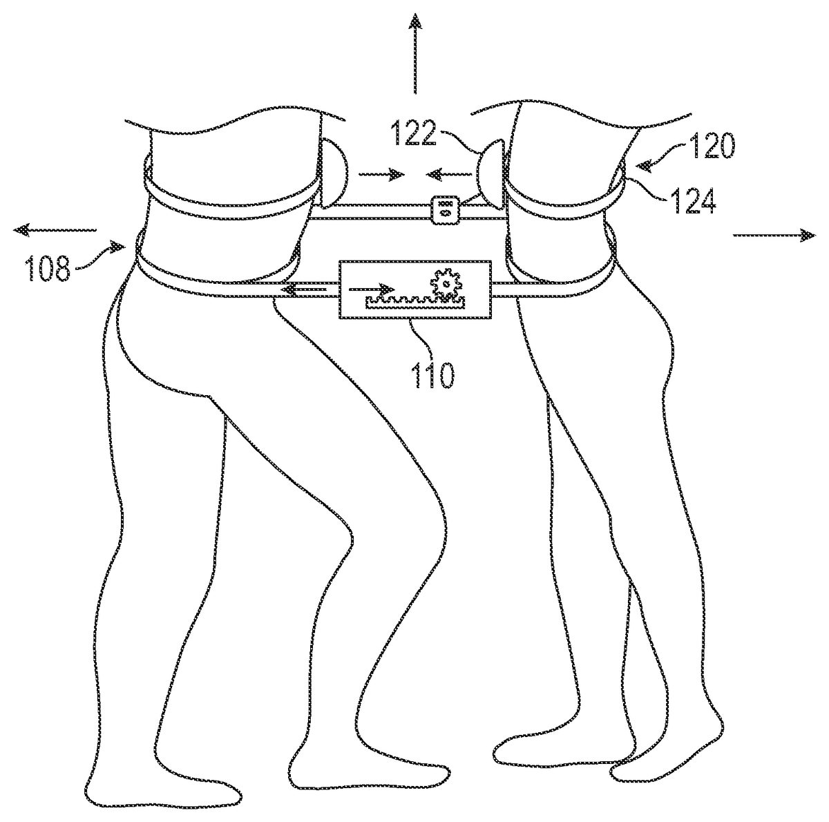
The belt or strap108can be placed on many parts of the players' bodies and fastened via conventional means, such as with Velcro®, snaps, belt buckle, or the like. For example, the strap(s) can be placed on a leg of each player so that the players have to pull their legs apart in order to engage a particular game action or function. The strap may also be placed around other players' parts such around their forearms, chests, hips, abdomens, etc.FIG. 12shows the TSD ofFIGS. 9 and 10placed around the waists of two players.
As another means of cooperative game play, the invention may also include a pressure sensitive device (PSD) which requires the players to press together in order to turn on or off the PSD. The PSD may include any device capable of measuring pressure exerted by the players, such as a switch, pad, button, etc. which provides variable input to the game CPU, such as a variable resistance pressure switch. The variable resistance switch may include an air bladder or weight scale mechanism to measure on/off pressure or amount of pressure depending on the game design. The PSD may be attached directly to the players' clothing or skin or may be attached to a belt, strap, or other device that goes around one or more of each of the players' body parts, including their heads, arms, legs, waists, abdomens, etc.
A preferred embodiment of the PSD120using an air bladder is shown inFIG. 11. The air bladder122shown is attached to a belt or strap124which in turn encircles the waist, abdomen, or other body part of the player.FIG. 12shows the PSD120on a strap124that is wrapped around the players' waists. Alternatively, the PSD120could be mounted on the players' foreheads (not shown) so the players would need to push their foreheads together to engage a particular game action. The surface of the PSD is preferably covered with some type of cloth, denim, padding, rubber, or other non-slip material to enable contact between the players and to protect the devices. Inside the PSD is a switch, mouse, or other device that measures the variable amount of pressure placed on the device by the players which is then communicated wirelessly or otherwise to the game CPU which in turn determines the movement of one or more game objects on the screen.
While in the foregoing specification this invention has been described in relation to certain preferred embodiments thereof, and many details have been set forth for purposes of illustration, it will be apparent to those skilled in the art that the invention is susceptible to additional embodiments and that certain of the details described herein may be varied considerably without departing from the basic principles of the invention.
Having described the invention with reference to particular compositions, theories of effectiveness, and the like, it will be apparent to those of skill in the art that it is not intended that the invention be limited by such illustrative embodiments or mechanisms, and that modifications can be made without departing from the scope or spirit of the invention, as defined by the appended claims. It is intended that all such obvious modifications and variations be included within the scope of the present invention as defined in the appended claims. The claims are meant to cover the claimed components and steps in any sequence which is effective to meet the objectives there intended, unless the context specifically indicates to the contrary.
Claims
- A video game controller for cooperative play by two or more players comprising: a game controller having a housing having a first portion being manipulable by a first player and a second portion being manipulable by a second player;an accelerometer in said game controller for sensing the orientation of the game controller;said accelerometer capable of communicating with a microprocessor, whereby said microprocessor is configured to communicate with a computer processing unit (CPU) that in turn displays a video game having at least one game object;whereby cooperative movement of the game controller by the players controls the movement of the game object;and further providing that the cooperative movement of the game controller is detected by a device selected from the group consisting of a tension sensitive device (TSD), a pressure sensitive device (PSD), and both a TSD and a PSD, said TSD and PSD being capable of measuring the amount of pressure cooperatively exerted on the game controller by the players;whereby the TSD comprises a potentiometer to measure the amount of pressure cooperatively exerted on the game controller by the players, said potentiometer comprising: a control shaft mounting a pinion;a gear rack engaging the pinion to rotate the control shaft in response to relative movement of the rack and pinion;and further providing that the rack and pinion measure the tension or resistance placed by the players on a belt or a strap that is wrapped around one or more portions of the players' bodies.
- A video game controller for cooperative play by two or more players comprising: a game controller having a housing having a first portion being manipulable by a first player and a second portion being manipulable by a second player;an accelerometer in said game controller for sensing the orientation of the game controller;said accelerometer capable of communicating with a microprocessor, whereby said microprocessor is configured to communicate with a computer processing unit (CPU) that in turn displays a video game having at least one game object;whereby cooperative movement of the game controller by the players controls the movement of the game object;and further providing that the cooperative movement of the game controller is detected by a device selected from the group consisting of a tension sensitive device (TSD), a pressure sensitive device (PSD), and both a TSD and a PSD, said TSD and PSD being capable of measuring the amount of pressure cooperatively exerted on the game controller by the players;whereby the PSD is a variable resistance switch (VRS) which measures the variable amount of pressure placed on the PSD by the players;and further providing that the VRS includes an air bladder or weight scale mechanism.
- A video game controller according to claim 1 whereby the housing has a third portion being manipulable by a third player.
- A video game controller according to claim 3 whereby the housing has a fourth portion being manipulable by a fourth player.
- A video game controller according to claim 2 whereby the housing has a third portion being manipulable by a third player.
- A video game controller according to claim 5 whereby the housing has a fourth portion being manipulable by a fourth player.
Disclaimer: Data collected from the USPTO and may be malformed, incomplete, and/or otherwise inaccurate.