U.S. Pat. No. 8,529,357
COMBINATION TABLET COMPUTER AND GAME CONTROLLER WITH FLEXIBLE BRIDGE SECTION
AssigneeWikipad, Inc.
Issue DateFebruary 28, 2013
Illustrative Figure
Abstract
An apparatus generally directed to a combination tablet computer and game controller. The tablet computer provides a plurality of sides, in which each of the sides are disposed between an electronic display screen and a back. The computer game controller provides side structures adjacent the tablet computer on at least two opposing sides. The computer game controller further preferably providing input module apertures and a camera. Preferably, each input module aperture selectively accepts either a game control module or a removable keyboard module. The input module apertures are preferably adjacent each of the at least two opposing sides of the tablet computer, and the camera communicates with each the electronic game controller and the tablet computer. The electronic game controller further provides an integrated transaction card input feature.
Description
DETAILED DESCRIPTION The present disclosure generally relates to a combination game controller and information input device directed to controlling electronic games and entry of information to a tablet computer, also referred to herein as video games, computer and applications games. The apparatus preferably includes a tablet computer, an electronic game communicating with the tablet computer, and an input device for controlling movement of a virtual object provided by the electronic game, and entry of information into the tablet computer. In a preferred embodiment, the input device includes a pair of opposing side structures adjacent opposing sides of plurality of sides of the tablet computer. The input device further preferably includes a plurality of input switches, wherein said input switches are adjacent each of the at least two opposing sides of the plurality of sides of the tablet computer, and a bridge structure disposed between the pair of sides to form a three sided structure. The third structure mitigates inadvertent removal of the tablet computer from the three sided structure when the tablet computer is fully nested within the three sided structure. Turning to the drawings,FIG. 1provides an exemplary game controller and information entry device (“G&D”)100capable of being used in accordance with various embodiments of the present invention. The exemplary G&D100has at least a tablet computer102that providing a plurality of sides, such as104,106,108, and126. Each of the plurality of sides104,106, and108are disposed between an electronic display screen110, of the tablet computer102, and a back112(shown byFIG. 2) of the tablet computer102operates. The G&D100further preferably includes an input device114. In a preferred embodiment, the input device114provides a pair of side structures,116and118. One of the pair of side structures, for example 116, is adjacent to and confines the tablet computer102on a first side, such as104of the plurality of sides104,106,108, and126of the tablet computer102. The ...
DETAILED DESCRIPTION
The present disclosure generally relates to a combination game controller and information input device directed to controlling electronic games and entry of information to a tablet computer, also referred to herein as video games, computer and applications games. The apparatus preferably includes a tablet computer, an electronic game communicating with the tablet computer, and an input device for controlling movement of a virtual object provided by the electronic game, and entry of information into the tablet computer. In a preferred embodiment, the input device includes a pair of opposing side structures adjacent opposing sides of plurality of sides of the tablet computer. The input device further preferably includes a plurality of input switches, wherein said input switches are adjacent each of the at least two opposing sides of the plurality of sides of the tablet computer, and a bridge structure disposed between the pair of sides to form a three sided structure. The third structure mitigates inadvertent removal of the tablet computer from the three sided structure when the tablet computer is fully nested within the three sided structure.
Turning to the drawings,FIG. 1provides an exemplary game controller and information entry device (“G&D”)100capable of being used in accordance with various embodiments of the present invention. The exemplary G&D100has at least a tablet computer102that providing a plurality of sides, such as104,106,108, and126. Each of the plurality of sides104,106, and108are disposed between an electronic display screen110, of the tablet computer102, and a back112(shown byFIG. 2) of the tablet computer102operates. The G&D100further preferably includes an input device114.
In a preferred embodiment, the input device114provides a pair of side structures,116and118. One of the pair of side structures, for example 116, is adjacent to and confines the tablet computer102on a first side, such as104of the plurality of sides104,106,108, and126of the tablet computer102. The second side structure of the pair of side structures, such as118, is adjacent to and confines the tablet computer102on a second side, such as108, of the plurality of sides104,106,108, and126of the tablet computer102, wherein the first and second sides, such as104and108, of the plurality of sides104,106,108, and126of the tablet computer102are opposing sides of the plurality of sides104,106,108, and126, of the tablet computer102.
In a preferred embodiment, the input device114further provides a plurality of removable game control modules120and122, wherein the removable game control modules120and122are adjacent each of the at least two opposing sides104and108, of the plurality of sides104,106,108, and126, of the tablet computer102, and a bridge structure124, disposed between the pair of side structures116and118, and adjacent the third side126, of the plurality of sides104,106,108, and126, of the tablet computer102.
In a preferred embodiment, the removable game control modules120and122may be removed from the input device114, and replaced by removable keyboard modules164and166, ofFIG. 8. To facilitate the exchange of modules, the input device preferably provides a pair of input module apertures170. The removable keyboard modules collectively form a full function keyboard and each provide an auxiliary electronic display screen (“ADS”)168, each ADS168having at least the functionality of the electronic display screen110.
In an alternate embodiment, shown byFIG. 10, the removable keyboard modules164and166are a pair of touch responsive electronic display screens172and174, each of the touch responsive electronic display screens having at least the functionality of the electronic display screen110, include the functionality of a mouse pad portions176and178, and selectively presents keys of a keyboard180and182for information entry. Preferably, the keys are virtual keys that respond to a touch by a user.
Returning toFIG. 1, preferably, the bridge structure124in combination with the pair of side structures116and118form a three sided structure128(ofFIG. 5) (also referred to herein as a u-shaped structure128of the input device114), in which the tablet computer102nests, such that the tablet computer102is confined by the u-shaped structure128, and the u-shaped structure128mitigates inadvertent removal of the tablet computer102from the u-shaped structure128when the tablet computer102is fully nested within the three sided structure128.
The G&D100ofFIG. 1, further preferably includes a video game130. Preferably, the video game130provides a virtual object132displayed by the electronic display screen110, the virtual object132is responsive to input from the input device114. An example of a response of the virtual object132would be movement of the virtual object132, or the loading of an alternate computer game, based on a predetermined signal provided by the input device114, or an appearance of a character. It is noted thatFIG. 1displays the housings of the plurality of switches, whereas at least some of the plurality of switches are shown in the partial cutaway ofFIG. 3.
FIG. 2depicts and reveals the back112of the tablet computer102. Further shown byFIG. 2, is the input device114, which provides a pair of trigger switches136and138, supported by their corresponding side structures116and118respectively.
FIG. 3shows that a predetermined number of the plurality of switches140, collaborate with each other to form an input apparatus142, the input apparatus142controls display of virtual objects displayed on the electronic display screen110of the tablet computer102. Preferably, the input apparatus142is a joystick142.FIG. 3further shows that the input device114provides a plurality of buttons144and119of the removable game control modules120, which activate corresponding switches145and121. The main function of the trigger138, the joystick142, and the buttons144and119of the removable game control modules120is to govern the movement/actions of a playable body/object or otherwise influence events in a video game130(ofFIG. 1) or an alternate computer game.
FIG. 4shows the G&D100, further includes a second joystick146, and a second button148, which are provided on the side structure116, adjacent the trigger136. WhileFIG. 5shows the central processing unit (CPU)150, of the input device114.
FIG. 6shows the input device114includes the CPU150, interacting with the plurality of switches152, which preferably include at least switches119of the removable game control modules120(ofFIG. 1), switches117of the removable game control modules122(ofFIG. 1),136,138,142,144,146, and148(ofFIGS. 2 and 3).FIG. 6further shows the input device114includes a communications protocol154providing the communication link between the tablet computer102, and the input device114. In a preferred embodiment, a Universal Serial Bus (USB) communications protocol is utilized. However, as those skilled in the art will recognize, the communications protocol154is not limited to a USB protocol.
FIG. 6further shows that the tablet computer102preferably includes at least a CPU156, interacting with the electronic display screen110, the video game130, a device driver158, which facilitates the interaction between the tablet computer102and the input device114, and a communications protocol160providing the communication link between the tablet computer102, and the input device114. In a preferred embodiment, a Universal Serial Bus (USB) communications protocol is utilized. However, as those skilled in the art will recognize, the communications protocol160is not limited to a USB protocol.
FIG. 7shows an alternative embodiment of an exemplary game controller162, in which the device driver158and the video game130are located in the input device114.
FIG. 8shows in a preferred embodiment, the G&D100includes a first camera184, on a first side of the tablet computer102, a second camera186, on the back side of the tablet computer102(shown byFIG. 9), a third camera188on a first side of the input device114, and a fourth camera190on the back side of the input device114(shown byFIG. 9).
In a preferred embodiment, each of the four cameras may selectively function independently, or may be used in conjunction with one another, and each of the four cameras184,186,188, and190are fully functional in capturing still and video images. Additionally, and preferably, the first and second cameras184and186, are fully operative, even when the tablet computer102is detached from the input device114, while the third and fourth cameras188and190are fully functional, even when the input device114is detached from the tablet computer102.
In a preferred embodiment, when the tablet computer102is nested in the input device114, the first and second cameras,184and186, are responsive, either independently or simultaneously, to input from either the tablet computer102, or the input device114, depending on which device is selected for control of the first and second cameras,184and186. Further, in the preferred embodiment, each the tablet computer102and the input device114, are configured with a Bluetooth protocol stack communication feature, which permits the user to operate the first and second cameras,184and186, of the tablet computer102with the input device114, even when the tablet computer102is detached from the input device114. Likewise, when the tablet computer102and the input device114are configured with a Bluetooth protocol stack communication feature, the user may operate the third and fourth cameras,188and190, of the input device114, using the tablet computer102. In other words, in the preferred embodiment, each of the four cameras184,186,188, and190, may be selectively operated, individually or collectively, whether or not the tablet computer102is nested within the input device114.
FIG. 9shows that in a preferred embodiment, the input device114, includes an auxiliary power source192, and an auxiliary data storage device194, which preferably includes a cache portion196. Preferably, the auxiliary power source192, is a lithium ion battery, which provides power to the input device114, and the tablet computer102, when the power source of the tablet computer102is depilated; and the auxiliary data storage device194is a solid state hard drive.
In the preferred embodiment, the cache196is sized to buffer synchronized input from each of the cameras184,186,188, and190, such that the auxiliary data storage device194may store and retrieve images, still or video, for display seamlessly, including a simultaneous output of video images recorded by each of the cameras184,186,188, and190.
In a non-limiting exemplary application of utilizing the cameras184,186,188, and190, the first camera184could be trained on an information presenter, while the second camera186is trained on a portion of an audience attending the presentation. The third camera188, could be trained on a screen used by the presenter for presenting their information to the audience, while the fourth camera is trained on an alternate portion of the audience. By simultaneously replaying the recorded presentation, a response of the audience to the information, and sequence of information being presented, may be analyzed for fostering improvements to the presentation.
FIG. 11shows an alternative embodiment of a video game controller200, which provides an integrated transaction card input feature202. Preferably, the integrated transaction card input feature202, includes a transaction card slot204, and a transaction card reader206. In a preferred embodiment, the transaction card reader206, is a magnetic strip reader, but as those skilled in the art will recognize, the transaction card reader can be, in the alternate: is an optical character recognition reader; a barcode reader; an object recognition reader, or a pattern recognition reader.
FIG. 12shows that in a preferred embodiment, a combination tablet computer and electronic game controller with an integrated point of sale device210preferably includes a tablet computer212, having a plurality of sides214, each of the plurality of sides214, are disposed between an electronic display screen216, of the tablet computer and a back218of the tablet computer, and an input device220, in electronic communication with the tablet computer212. The input device220preferably provides side structures222, adjacent to and confining the tablet computer on at least two opposing sides of the plurality of sides214of the tablet computer212. The input device220, further preferably provides input module apertures224, each input module aperture224, selectively accepts either a game control module, such as102and122ofFIG. 1, or a removable keyboard module, such as226and228. Preferably, the input module apertures224are adjacent each of the at least two opposing sides of the plurality of sides214of the tablet computer212.
FIG. 12further shows that in a preferred embodiment, the combination tablet computer and electronic game controller with an integrated point of sale device210preferably includes a camera230, communicating with each the input device220, and the tablet computer212. The camera230, selectively captures either still or video images, and that the input device220, further provides an integrated transaction card input feature232, which interacts with a transaction card234, and that preferably, the input device is an electronic game controller220. Preferably, the camera230is a first camera, having a lens facing the user while the user is facing the electronic display screen216, and includes at least a second camera, such as186or190(ofFIG. 9), having a lens facing in a direction opposite that of the first camera184.
FIG. 12additionally shows an application236, displayed on the electronic display screen216, of the tablet computer212. Preferably, the application236, displayed on the electronic display screen216of the tablet computer212, is a point of sale transactional computer application, which interacts with the electronic game controller220and the tablet computer212.
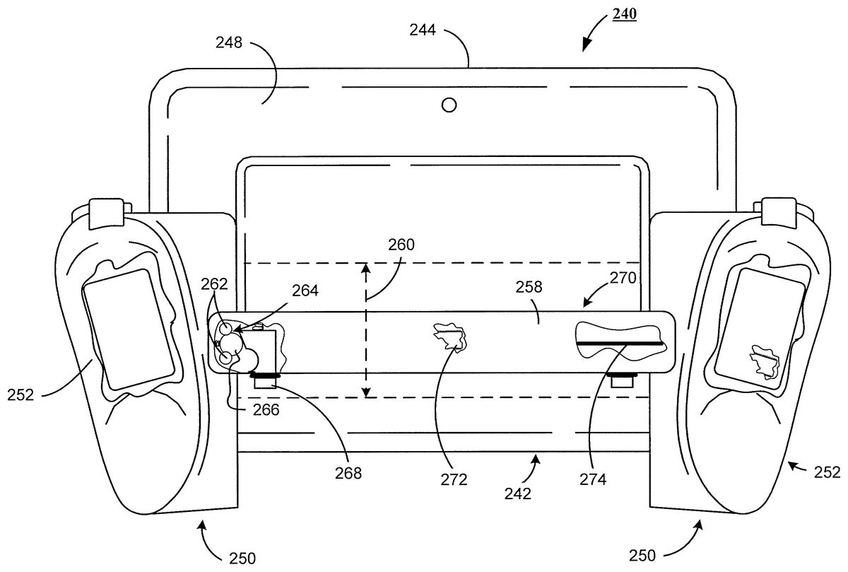
FIG. 13shows an alternative embodiment of a combination tablet computer and electronic game control240(also referred to herein as a device240). The tablet computer242, preferably provides a plurality of sides244, each of the plurality of sides are disposed between an electronic display screen246, of the tablet computer242, and a back248of the tablet computer242.
Preferably, the electronic game controller250(also referred to herein as input device250), is in electronic communication with the tablet computer242. Preferably, the input device250, provides a pair of control modules252. The pair of control modules252, are adjacent to and confining the tablet computer242, on at least two opposing sides of the plurality of sides244, of the tablet computer242. The pair of control modules252, preferably provide input module apertures254, each input module aperture254, secures an instructional input device256. Preferably, the input module apertures254, are adjacent each of the at least two opposing sides of the plurality of sides244, of the tablet computer242.
FIG. 14shows the back248, of the tablet computer242, and the tablet computer242, partially positioned within the input device250.FIG. 14further shows a structural bridge258, securing the pair of control modules252, one to the other, and communicating with the back248, of the tablet computer242, at a mid-region260, of the back248, of the tablet computer242.
FIG. 14further shows that the pair of control modules252, provide a confinement boss262, and the confinement boss262provides a fastening detent264. The fastening detent264, interacts with a retention member266, to secure the structural bridge258, to the pair of control modules252. In a preferred embodiment, the retention member266, is responsive to a catch268, which preferably is a spring activated catch268, and the retention member268is preferably a spring loaded retention member268. Still further,FIG. 14, shows that in a preferred embodiment, the structural bridge258, provides a communication link270, which passing signals between the pair of control modules252.
Continuing withFIG. 14, in a preferred embodiment, the communication link270, provides a communication module272, and in the alternative, provides a signal pathway274, for use in passing signals between the pair of control modules252. In a preferred embodiment, the communication module272is a wireless communication module272, which operates in a frequency range of 2.4 GHz. In an alternate preferred embodiment, the wireless communication module272is a personal area network. As those skilled in the art, a personal area network (PAN) is a computer network used for communication among computerized devices, including telephones and personal digital assistants. PANs can be used for communication among the personal devices themselves (intrapersonal communication), or for connecting to a higher level network and the Internet (an uplink). A wireless personal area network (WPAN) is a PAN carried over wireless network technologies such as IrDA, Bluetooth, Wireless USB, Z-Wave, ZigBee, or even Body Area Network. The reach of a WPAN varies from a few centimeters to a few meters. A PAN may also be carried over wired computer buses such as USB and FireWire.
In an embodiment that utilizes the signal pathway274, as the communication link, the signal pathway274may be in the form of a metallic conductor, a fiber optic conductor, a conductive polymer, or the conductive layer of a flex circuit. The skilled artisan will further appreciate that the structural bridge258(ofFIG. 14), or276(ofFIG. 15) may be either formed from a ridged material, such as a ridged polymer, or from a flexible material, such as a flexible polymer. In a preferred embodiment, when a flexible material is selected, and the signal pathway274is a wired pathway, the signal pathway274may be coupled externally to the structural bridge276, as shown byFIG. 15.
FIG. 15further shows that in a preferred embodiment, the instructional input device256, may be an electronic game control module278(which may be either removable, or fixed), or a keyboard module280(ofFIG. 13, which may be either removable, or fixed).
It is to be understood that even though numerous characteristics and configurations of various embodiments of the present invention have been set forth in the foregoing description, together with details of the structure and function of various embodiments of the invention, this detailed description is illustrative only, and changes may be made in detail, especially in matters of structure and arrangements of parts within the principles of the present invention to the full extent indicated by the broad general meaning of the terms in which the appended claims are expressed. For example, the particular elements may vary depending on the particular tablet computer without departing from the spirit and scope of the present invention.
Claims
- A device comprising: a tablet computer, the tablet computer providing a plurality of sides, each of the plurality of sides are disposed between an electronic display screen of the tablet computer and a back of the tablet computer;an input device in electronic communication with the tablet computer, the input device providing a pair of control modules, the pair of control modules adjacent to and confining the tablet computer on at least two opposing sides of the plurality of sides of the tablet computer, the pair of control modules providing input module apertures, each input module aperture secures an instructional input device, wherein said input module apertures are adjacent each of the at least two opposing sides of the plurality of sides of the tablet computer;and a structural bridge securing the pair of control modules one to the other and communicating with the back of the tablet computer at a mid-region of the back of the tablet computer, and wherein the input device is an electronic game controller, in which the pair of control modules provide a confinement boss, and in which the structural bridge comprising: a communication link passing signals between the pair of control modules;and a fastening mechanism cooperating with the confinement boss to secure the pair of control modules one to the other.
- The device of claim 1 , in which the instructional input device is a removable input device.
- The device of claim 1 , in which the instructional input device is a game control module.
- The device of claim 1 , in which the instructional input device is a keyboard module.
- The device of claim 2 , in which the removable instructional input device is a removable game control module.
- The device of claim 2 , in which the removable instructional input device is a removable keyboard module.
- The device of claim 1 , in which the structural bridge is a ridged structure.
- The device of claim 7 , in which the rigid structural bridge is a removable rigid structure.
- The device of claim 1 , in which the structural bridge is a flexible structure.
- The device of claim 9 , in which the flexible structural bridge is a removable rigid structure.
- The device of claim 1 , in which the communication link is a signal pathway.
- The device of claim 11 , in which the signal pathway is a metallic pathway.
- The device of claim 11 , in which the signal pathway is a fiber optic pathway.
- The device of claim 1 , in which the communication link provides a communication module.
- The device of claim 14 , in which the communication module is a wired communication module.
- The device of claim 14 , in which the communication module is a wireless communication module.
- The device of claim 16 , in which the wireless communication module operates in a frequency range of 2.4 GHz.
- The device of claim 16 , in which the wireless communication module is a personal area network.
- The device of claim 16 , in which the wireless communication module utilizes infrared technology for data transactions.
Disclaimer: Data collected from the USPTO and may be malformed, incomplete, and/or otherwise inaccurate.