U.S. Pat. No. 8,523,677
CAMERA CONTROL FOR THIRD-PERSON CONSOLE VIDEO GAME
AssigneeMicrosoft Corporation
Issue DateDecember 29, 2008
Illustrative Figure
Abstract
In a third-person shooter video game, the viewing perspective is smoothly transitioned between an “explorer” viewpoint and a “ready” viewpoint as game conditions change. In the “explorer” viewpoint, scenes are depicted from a camera positioned behind and removed from a character. The explorer viewpoint offers a wide angle of view of the surrounding combat area, enabling the game player to scout the terrain. In the “ready” viewpoint, scenes are depicted from the camera as it is repositioned close to the character. The ready viewpoint provides a narrower angle of view to facilitate better aiming when the character is engaged in armed combat. The transition between the explorer and ready viewpoints tracks a non-linear path.
Description
The same numbers are used throughout the disclosure and figures to reference like components and features. DETAILED DESCRIPTION The following disclosure describes a camera control technique for a third-person shooter video game. For discussion purposes, the camera control technique is described in the context of a squad-based shooter video game for a console-based gaming system. In particular, exemplary screen shots showing various camera positions are taken from the video game title, Brute Force, which is developed for Microsoft's Xbox® gaming system. With squad-based games, a player controls a squad of characters, rather than just a single character. The player can give orders to one or more characters of the squad, and the characters carry out the orders without direct intervention from the player. The gaming system will be described first, followed by a discussion of the camera control technique. Gaming System FIG. 1shows an exemplary gaming system100. It includes a game console102and up to four controllers, as represented by controllers104(1) and104(2). The game console102is equipped with an internal hard disk drive and a portable media drive106. The portable media drive106supports various forms of portable storage media as represented by optical storage disc108. Examples of suitable portable storage media include DVD, CD-ROM, game discs, game cartridges, and so forth. The game console102has four slots110on its front face to support up to four controllers, although the number and arrangement of slots may be modified. A power button112and an eject button114are also positioned on the front face of the game console102. The power button112switches power to the game console and the eject button114alternately opens and closes a tray of the portable media drive106to allow insertion and extraction of the storage disc108. The game console102connects to a television or other display (not shown) via A/V interfacing cables120. A power cable122provides power to the game ...
The same numbers are used throughout the disclosure and figures to reference like components and features.
DETAILED DESCRIPTION
The following disclosure describes a camera control technique for a third-person shooter video game. For discussion purposes, the camera control technique is described in the context of a squad-based shooter video game for a console-based gaming system. In particular, exemplary screen shots showing various camera positions are taken from the video game title, Brute Force, which is developed for Microsoft's Xbox® gaming system. With squad-based games, a player controls a squad of characters, rather than just a single character. The player can give orders to one or more characters of the squad, and the characters carry out the orders without direct intervention from the player. The gaming system will be described first, followed by a discussion of the camera control technique.
Gaming System
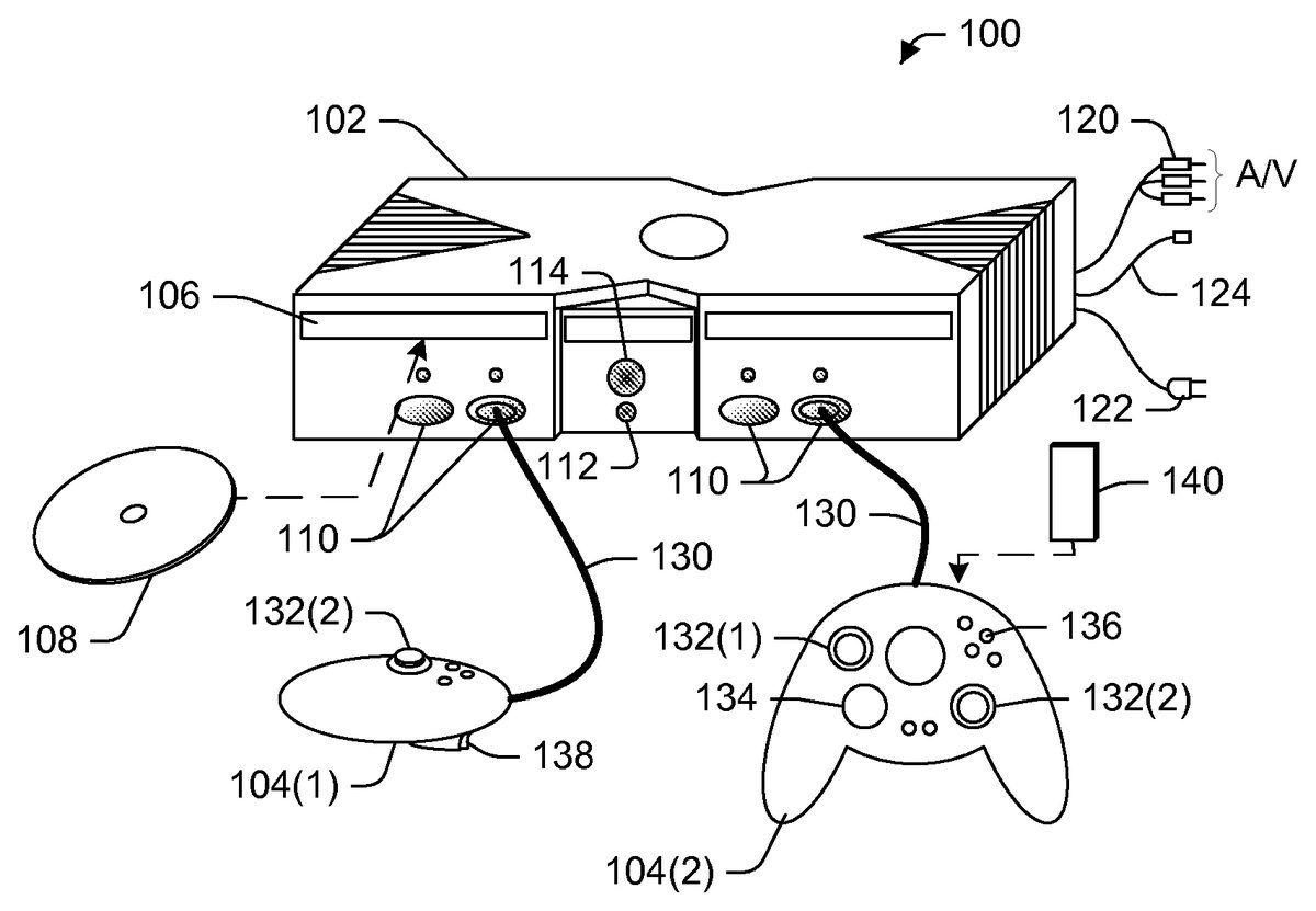
FIG. 1shows an exemplary gaming system100. It includes a game console102and up to four controllers, as represented by controllers104(1) and104(2). The game console102is equipped with an internal hard disk drive and a portable media drive106. The portable media drive106supports various forms of portable storage media as represented by optical storage disc108. Examples of suitable portable storage media include DVD, CD-ROM, game discs, game cartridges, and so forth.
The game console102has four slots110on its front face to support up to four controllers, although the number and arrangement of slots may be modified. A power button112and an eject button114are also positioned on the front face of the game console102. The power button112switches power to the game console and the eject button114alternately opens and closes a tray of the portable media drive106to allow insertion and extraction of the storage disc108.
The game console102connects to a television or other display (not shown) via A/V interfacing cables120. A power cable122provides power to the game console. The game console102may further be equipped with internal or externally added network capabilities, as represented by the cable or modem connector124to facilitate access to a network, such as a local area network (LAN) or the Internet.
Each controller104is coupled to the game console102via a wire or wireless interface. In the illustrated implementation, the controllers are USB (Universal Serial Bus) compatible and are connected to the console102via serial cables130. The controller102may be equipped with any of a wide variety of user interaction mechanisms. As illustrated inFIG. 1, each controller104is equipped with two thumbsticks132(1) and132(2), a directional or D-pad134, surface buttons136, and two triggers138. These mechanisms are merely representative, and other known gaming mechanisms may be substituted for or added to those shown inFIG. 1.
A memory unit (MU)140may be inserted into the controller104to provide additional and portable storage. Portable memory units enable users to store game parameters and transport them for play on other consoles. In the described implementation, each controller is configured to accommodate two memory units140, although more or less than two units may be employed in other implementations.
The gaming system100is capable of playing, for example, games, music, and videos. With the different storage offerings, titles can be played from the hard disk drive or the portable medium108in drive106, from an online source, or from a memory unit140. A sample of what the gaming system100is capable of playing back includes:1. Game titles played from CD and DVD discs, from the hard disk drive, or from an online source.2. Digital music played from a CD in the portable media drive106, from a compressed file on the hard disk drive (e.g., Windows Media Audio (WMA) format), or from online streaming sources.3. Digital audio/video played from a DVD disc in the portable media drive106, from a file on the hard disk drive (e.g., Windows Media Video (WMV) format), or from online streaming sources.
FIG. 2shows functional components of the gaming system100in more detail. The game console102has a central processing unit (CPU)200and a memory controller202that facilitates processor access to various types of memory, including a flash ROM (Read Only Memory)204, a RAM (Random Access Memory)206, a hard disk drive208, and the portable media drive106. The CPU200is equipped with a level 1 cache210and a level 2 cache212to temporarily store data and hence reduce the number of memory access cycles, thereby improving processing speed and throughput.
The CPU200, memory controller202, and various memory devices are interconnected via one or more buses, including serial and parallel buses, a memory bus, a peripheral bus, and a processor or local bus using any of a variety of bus architectures. By way of example, such architectures can include an Industry Standard Architecture (ISA) bus, a Micro Channel Architecture (MCA) bus, an Enhanced ISA (EISA) bus, a Video Electronics Standards Association (VESA) local bus, and a Peripheral Component Interconnect (PCI) bus.
As one suitable implementation, the CPU200, memory controller202, ROM204, and RAM206are integrated onto a common module214. In this implementation, ROM204is configured as a flash ROM that is connected to the memory controller202via a PCI (Peripheral Component Interconnect) bus and a ROM bus (neither of which are shown). RAM206is configured as multiple DDR SDRAM (Double Data Rate Synchronous Dynamic RAM) modules that are independently controlled by the memory controller202via separate buses (not shown). The hard disk drive208and portable media drive106are connected to the memory controller via the PCI bus and an ATA (AT Attachment) bus216.
A 3D graphics processing unit220and a video encoder222form a video processing pipeline for high speed and high resolution graphics processing. Data is carried from the graphics processing unit220to the video encoder222via a digital video bus (not shown). An audio processing unit224and an audio codec (coder/decoder)226form a corresponding audio processing pipeline with high fidelity and stereo processing. Audio data is carried between the audio processing unit224and the audio codec226via a communication link (not shown). The video and audio processing pipelines output data to an A/V (audio/video) port228for transmission to the television or other display. In the illustrated implementation, the video and audio processing components220-228are mounted on the module214.
Also implemented on the module214are a USB host controller230and a network interface232. The USB host controller230is coupled to the CPU200and the memory controller202via a bus (e.g., PCI bus) and serves as host for the peripheral controllers104(1)-104(4). The network interface232provides access to a network (e.g., LAN, Internet, etc.) and may be any of a wide variety of various wired or wireless interface components including an Ethernet card, a modem, a Bluetooth module, a cable modem, and the like.
The game console102has two dual controller support subassemblies240(1) and240(2), with each subassembly supporting two game controllers104(1)-104(4). A front panel I/O subassembly242supports the functionality of the power button112and the eject button114, as well as any LEDs (light emitting diodes) or other indicators exposed on the outer surface of the game console. The subassemblies240(1),240(2), and242are coupled to the module214via one or more cable assemblies244.
Eight memory units140(1)-140(8) are illustrated as being connectable to the four controllers104(1)-104(4), i.e., two memory units for each controller. Each memory unit140offers additional storage on which games, game parameters, and other data may be stored. When inserted into a controller, the memory unit140can be accessed by the memory controller202.
A system power supply module250provides power to the components of the gaming system100. A fan252cools the circuitry within the game console102.
A console user interface (UI) application260is stored on the hard disk drive208. When the game console is powered on, various portions of the console application260are loaded into RAM206and/or caches210,212and executed on the CPU200. The console application260presents a graphical user interface that provides a consistent user experience when navigating to different media types available on the game console.
The game console102implements a cryptography engine to perform common cryptographic functions, such as encryption, decryption, authentication, digital signing, hashing, and the like. The cryptography engine may be implemented as part of the CPU200, or in software stored in memory (e.g., ROM204, hard disk drive208) that executes on the CPU, so that the CPU is configured to perform the cryptographic functions.
The gaming system100may be operated as a standalone system by simply connecting the system to a television or other display. In this standalone mode, the gaming system100allows one or more players to play games, watch movies, or listen to music. However, with the integration of network connectivity made available through the network interface232, the gaming system100may further be operated as a participant in a larger network gaming community.
Video games may be stored on various storage media for play on the game console. For instance, a video game may be stored on the portable storage disc108, which is read by drive106. Alternatively, the video game may be stored in hard disk drive208, being transferred from a portable storage medium or downloaded from a network. During play, portions of the game are temporarily loaded into RAM memory206, caches210and212, and executed by the CPU200. One particular video game of the shooter genre is described next to help explain camera control techniques used in third-person video games.
Camera Control
In a third-person shooter video game, scenes are depicted from a perspective removed from the character being controlled. The scenes are created as if taken from a camera viewpoint residing behind the character.
FIG. 3illustrates a third-person camera control technique300for a video game. The camera control technique300controls movement of a camera perspective, represented by camera302, between two different viewpoints taken from behind a controlled character304. A first camera viewpoint306positions the camera302farthest from the character304. This viewpoint is referred to as the “explorer” viewpoint, as the camera follows the character through the action from a predefined distance that enables the player to scout the terrain. The explorer viewpoint306provides a wide angle of view308that allows the player to see more of the surrounding area as the character moves about.
A second camera viewpoint310positions the camera302closest to the character304. This viewpoint is referred to as the “ready” viewpoint, as the camera is positioned to facilitate better aiming when the character shoots at a target. The ready viewpoint310provides a narrower angle of view312as the player focuses on the target.
The camera302is moved along a non-linear arc320between the two viewpoints306and310. The arc320facilitates a smooth and natural viewing perspective as the camera transitions from the hovering explorer viewpoint306to the close-up ready viewpoint310. Selection of the appropriate viewpoint is governed by certain events that occur during game play. In one implementation, the explorer viewpoint306is the default camera position. Then, upon occurrence of certain predefined events, the camera is moved to the ready viewpoint310along arc320. The predefined events are associated with readying the character for combat. These events are described below in more detail. The camera remains in the ready viewpoint as long as one of the events occurs. When no predefined event is present, the camera transitions back along arc320to the explorer viewpoint306after a predefined delay period.
FIG. 4shows an exemplary scene400from the squad-based shooter video game title, Brute Force, when the camera is in the explorer viewpoint. In scene400, the “Tex” character402from the squad is illustrated in a combat scene. The Tex character402is currently the character being directly controlled by the player. The other characters from the squad are not shown in this scene, but a squad status display404and a radar display406keeps the player informed as to the other characters location and current assignment. For the selected character (e.g., Tex), the player controls where that character moves, what that character sees, and how that character acts. Additionally, the player can issue commands to one or more other characters on the squad, such as where to move and how to function in combat. Artificial intelligence built into the video game controls the other non-selected characters of the squad to perform functions consistent with the commands instructed by the player. The characters' current commands are depicted on the squad status display404.
In the explorer viewpoint, the camera is positioned behind the selected character, as represented by the rearward hovering viewing perspective taken from behind the Tex character402inFIG. 4. This camera viewpoint offers a relatively wide angle of view to see more of the surrounding area. From the explorer viewpoint, the camera is pivotal so that the player can look around the scene by actuating the thumbstick132, or other actuator, on the controller104. This ability to see more of the combat area and pivot around for wide area viewing enables the player to better grasp the current landscape and combat scenario and thereby develop a more informed strategy for attack.
At the center of the screen is a reticle410, which is a grid or pattern that one would see when sighting a target through an eyepiece of a weapon scope. Unlike conventional shooter games, where the player moves the reticle around the screen at various targets, the reticle410in the Brute Force shooter game remains stationary. The player maneuvers the controlled character in order to position the stationary reticle on a desired target. With the camera behind the character in the explorer viewpoint, there is the possibility of obstacles interfering with a line-of-sight of the character. Additionally, in some situations, the character might get in the way of the reticle410and hence the target at which the player is aiming.
To minimize line-of-sight obstructions, the camera position is controlled to move from the explorer viewpoint to the ready viewpoint when certain predefined events occur. One example event is when the player partially squeezes the trigger138on the controller104. Such action causes the character to ready its weapon, while the camera moves to the ready viewpoint in order to facilitate better aiming and shooting. Another event is when the reticle410is positioned over an enemy.
A third event that triggers transition to the ready viewpoint is when the player moves into a certain region on the combat map. That is, the game developer may preset certain regions that force the camera perspective to the ready viewpoint. For example, suppose the character enters a forest. In such an environment, the camera might otherwise being constantly moving in and out between viewpoints to avoid trees or other obstacles from obstructing the player's vision of the character. By forcing the camera to the ready viewpoint, the annoying in-and-out bouncing is eliminated.
FIG. 5shows the same scene400, but with the camera is in the ready viewpoint. The camera is moved much closer to the controlled Tex character402and the angle of view is narrowed. From this viewpoint, the player is better able to aim at targets through the reticle410. The player positions the character to place the reticle410over intended targets, and then fires at the target by squeezing trigger138on controller104.
The camera remains in the ready viewpoint as long as any one of the conditions is met (e.g., player is actuating trigger138, character is located in specified region, or reticle is positioned over an enemy). When these conditions are no longer met for a predefined period of time, the camera transitions back to the explorer viewpoint ofFIG. 4.
It may be possible for the character to partially or completely obscure the player's vision of the reticle410in either the explorer or ready viewpoints. In this situation, the character becomes translucent so that the player can see through the character to view the reticle410and underlying target.
Transitioning Between Viewpoints
FIGS. 6 and 7show one exemplary procedure for transitioning the camera between the explorer viewpoint and the ready viewpoint. When the camera is in the explorer viewpoint, the gaming system continually evaluates whether certain conditions dictate movement of the camera to the ready viewpoint. When the camera is in the ready viewpoint, the gaming system continually evaluates whether the conditions are still being met within a prescribed timeout period.
The processes for transitioning between these viewpoints are described separately below. The processes are illustrated as a series of blocks that represent individual operations or acts performed by the gaming system in response to executing the video game. The processes may be implemented in any suitable hardware, software, firmware, or combination thereof. In the case of software and firmware, processes represent sets of operations implemented as computer-executable instructions stored in memory and executable by one or more processors.
Explorer-to-Ready Transition
FIG. 6shows a process600for determining when to transition from the explorer viewpoint to the ready viewpoint. At block602, the camera is initially positioned at the explorer viewpoint. With the camera in this state, the gaming system evaluates several conditions to decide whether to move the camera to the ready viewpoint. Three representative conditions are examined at blocks604,606, and608. More or fewer conditions may be employed.
At block604, the gaming system determines whether the player has squeezed the trigger138. This affirmative action suggests that the player has a desire to shoot at a target, or at least be ready to shoot. If this event does not occur (i.e., the “No” branch from block604), the gaming system determines whether the reticle is positioned over a target (block606). By positioning the reticle over a target, the gaming system anticipates the player's desire to shoot at the target. If neither the first nor the second condition is present (i.e., the “No” branch from block606), the gaming system determines whether the controlled character has moved to a specified region of the combat map that is associated with the ready viewpoint (block608). If none of the conditions is met (i.e., the “No” branch from block608), the camera remains at the explorer viewpoint (block602).
Conversely, if anyone of the conditions is met, such as the trigger is actuated (i.e., the “Yes” branch from block604) or the reticle is positioned over a target (i.e., the “Yes” branch from block606) or the character is in a specified ready region (i.e., the “Yes” branch from block608), the camera is transitioned smoothly along the non-linear path to the ready viewpoint (block610).
Ready-to-Explorer Transition
FIG. 7shows a process700for determining when to transition from the ready viewpoint to the explorer viewpoint. At block702, the camera is currently positioned at the ready viewpoint. At block704, the gaming system sets a timer for a programmable delay period (e.g.,20seconds). With the camera in the ready state, the gaming system evaluates whether any of the conditions to keep the camera in the ready viewpoint are still valid. The same three representative conditions are examined at blocks706,708, and710. As before, more or fewer conditions may be employed.
At block706, the gaming system determines whether the player continues to press the trigger138. If this event does not occur (i.e., the “No” branch from block706), the gaming system determines whether the reticle is positioned over a target (block708). If neither the first nor second condition is present (i.e., the “No” branch from block708), the gaming system determines whether the controlled character has moved to a pre-specified region of the combat map that is associated with the ready viewpoint (block710). If no conditions are met (i.e., the “No” branch from block710), the gaming system determines whether the delay period has expired (block712). If not (i.e., the “No” branch from block712), the gaming system continues to evaluate the conditions. Conversely, if anyone of the conditions is met before the time delay expires, the camera remains positioned at the ready viewpoint and the timer is reset.
When no conditions are met and the delay period expires (i.e., the “Yes” branch from block712), the camera is transitioned smoothly back along the non-linear path to the explorer viewpoint (block714).
CONCLUSION
Although the invention has been described in language specific to structural features and/or methodological acts, it is to be understood that the invention defined in the appended claims is not necessarily limited to the specific features or acts described. Rather, the specific features and acts are disclosed as exemplary forms of implementing the claimed invention.
Claims
- A method comprising: presenting a scene from a first camera viewpoint remote from a character being controlled;depicting an aiming reticle, the aiming reticle from a third-person perspective remaining stationary such that the character being controlled moves relative to the reticle in order to position the reticle on a target;in response to an occurrence of an event, wherein the event comprises a placement of the aiming reticle over the target, transitioning to present the scene from a second camera viewpoint closer to the character being controlled;and transitioning back to the first camera viewpoint after the event ceases to exist and a time delay lapses.
- The method as recited in claim 1 , wherein the event further comprises at least one of: the character being placed in a combat ready state, a player-actuation of a controller directing the character to fire a weapon, and a movement of the character into a combat region.
- The method as recited in claim 1 , further comprising presenting the scene from the first camera viewpoint with a first angle of view and presenting the scene from the second camera viewpoint with a second angle of view different than the first angle of view.
- The method as recited in claim 3 , wherein the first angle of view is wider than the second angle of view.
- The method as recited in claim 1 , wherein the character becomes translucent when the character at least partially overlaps the aiming reticle.
- A method, comprising: moving a viewing perspective of scenes in a video game between an explorer viewpoint that shows the scenes from a third-person perspective taken behind and remote from a character being controlled and a ready viewpoint that shows the scenes from a third-person perspective taken from behind, but close to, the character;and depicting a reticle to assist in aiming at a target, the reticle remaining stationary such that the character being controlled moves relative to the reticle in order to position the reticle on a desired target, wherein the explorer viewpoint is a default, and the viewing perspective is moved to the ready viewpoint in response to at least one of the following conditions: player-actuation of a controller that is indicative of shooting;placement of an aiming reticle over a target;or movement of the character into a specified combat region.
- The method as recited in claim 6 , wherein the viewing perspective transitions between the explorer viewpoint and the ready viewpoint along a non-linear path.
- The method as recited in claim 6 , wherein the scenes are depicted at the explorer viewpoint as if taken through a first angle of view and the scenes are depicted at the ready viewpoint as if taken through a second angle of view different than the first angle of view.
- The method as recited in claim 8 , wherein the first angle of view is wider than the second angle of view.
- The method as recited in claim 9 , wherein the viewing perspective is returned from the ready viewpoint to the explorer viewpoint when none of the conditions arises for a specified time period.
- The method as recited in claim 6 , further comprising: causing the character to become translucent when the character at least partially blocks the reticle.
- A computer-readable memory storing computer executable instructions that, when executed by a processor, perform acts comprising: displaying scenes from a third-person perspective relative to a character being controlled in a video game, wherein the third-person perspective including an explorer viewpoint remote from the character that trails the character as the character moves around and a ready viewpoint close to the character;depicting a reticle to assist in aiming at a target, the reticle remaining stationary such that the character being controlled moves relative to the reticle in order to position the reticle on the target;and moving between the explorer viewpoint and the ready viewpoint as events change in the video game, wherein the moving comprises changing from the ready viewpoint to the explorer viewpoint after a predefined event ceases to exist and a specified time delay lapses, wherein the moving comprises changing from the explorer viewpoint to the ready viewpoint if one of the following events occurs: sensing player-actuation of a controller that is indicative of shooting;placement of the reticle over the target;or positioning of the character in a pre-specified combat region.
- The computer-readable memory as recited in claim 12 , wherein the moving further comprises changing from the explorer viewpoint to the ready viewpoint when the character is readied for shooting.
- The computer-readable memory as recited in claim 12 , wherein the moving comprises smoothly shifting the third-person perspective along a non-linear path between the explorer viewpoint and the ready viewpoint.
- The computer-readable memory as recited in claim 12 , further comprising computer executable instructions that, when executed by a processor, cause the character to become translucent when the character at least partially blocks the reticle.
- A console-based shooter video game, the console-based shooter video game comprising computer executable instructions stored on computer-readable media that, when executed by a processor, perform acts comprising: facilitating combat action during which a player controls at least one character from a third-person perspective;depicting action from an explorer viewpoint residing behind and removed from the character being controlled that enables a player to view a greater surrounding area;and transitioning from the explorer viewpoint to a ready viewpoint residing behind and near the character being controlled that enables the player to aim at potential targets, the transition occurring in response to an event related to readying the character to shoot, the shooter video game transitioning back to the explorer viewpoint when the character is no longer being readied to shoot and a specified time delay lapses and including a stationary reticle wherein the character is maneuverable relative to the stationary reticle in order to position the stationary reticle, wherein the event comprises a movement of the character into a combat region.
- The console-based shooter video game as recited in claim 16 , wherein the event further comprises: sensing player-actuation of a controller that is indicative of shooting;and placement of an aiming reticle over a target.
- A console-based shooter video game, the console-based shooter video game comprising computer executable instructions stored on a computer-readable media that, when executed by a processor, perform acts comprising: facilitating combat action;and transitioning from an explorer viewpoint to a ready viewpoint residing behind and near a character that enables a player to aim at potential targets, the transition occurring in response to movement of the character into a pre-specified combat region, the console-based shooter video game including a stationary reticle wherein the character is maneuverable relative to the stationary reticle in order to position the stationary reticle on a desired target.
- The console-based shooter video game as recited in claim 18 , wherein the shooter video game transitions back to the explorer viewpoint when the character is moved out of the pre-specified combat region.
- The console-based shooter video game as recited in claim 18 , the shooter video game being further configured to depict at least one of a squad status display and a radar display corresponding to a squad of player-selectable characters.
Disclaimer: Data collected from the USPTO and may be malformed, incomplete, and/or otherwise inaccurate.