U.S. Pat. No. 8,517,837
Control Unit For A Video Games Console Provided With A Tactile Screen
AssigneeBigben Interactive, Société Anonyme
Issue DateAugust 10, 2012
Illustrative Figure
Abstract
A control unit for a home video game console, including a control unit body, a display supported by the control unit body for displaying information and/or images relating to the game, and a recess defined by the control unit body for accommodating a second control unit equipped with an accelerometer and/or with tilt sensors. The recess has an electrical connection between the two control units, wherein the displayed information and/or images are changed in response to signals received by the accelerometer and/or the tilt sensors and transmitted to the display through the electrical connection. A touch screen overlying at least partially over the display, detects tactile commands including a sequence of locations touched on the screen able to change the displayed information and/or images.
Description
Like reference symbols in the various drawings indicate like elements. DETAILED DESCRIPTION Referring toFIG. 4, in some implementations, a game controller100includes a first control unit102having a second control unit104inserted within. This game controller is designed to be integrated into a game system similar to those presented inFIGS. 2 and 3. In some examples, the first control unit102includes a display106, an LCD screen for example, enabling the display of information and/or images relating to the game in progress. This LCD screen is overlaid with a touch screen108capable of detecting tactile commands in the form of a sequence of locations touched on the screen. These commands make it possible to modify the displayed information and/or images. The first control unit102also includes a recess110designed to accommodate the second control unit104. Advantageously, the first control unit includes only the touch screen as a control member for direct interaction with the flow of the game and hence with the displayed information and/or images. The second control unit104is a unit similar to that illustrated inFIG. 1. This control unit104is equipped with an accelerometer and/or with tilt sensors (not shown). An electrical connection (138,FIG. 6;140,FIG. 1) between the two control units is provided such that the signals received by the accelerometer and/or the tilt sensors also make it possible to change the information and/or images displayed on the LCD screen. The recess110of the first control unit is made on the face bearing the display106, so that control buttons112of the second control unit, placed on its upper surface, remain accessible. The control buttons112can be used in the traditional manner. The signals received from the accelerometer and/or from the tilt sensors via the electrical connection with the second control unit and the tactile commands received via the touch screen are able to simultaneously change the displayed information and/or images. ...
Like reference symbols in the various drawings indicate like elements.
DETAILED DESCRIPTION
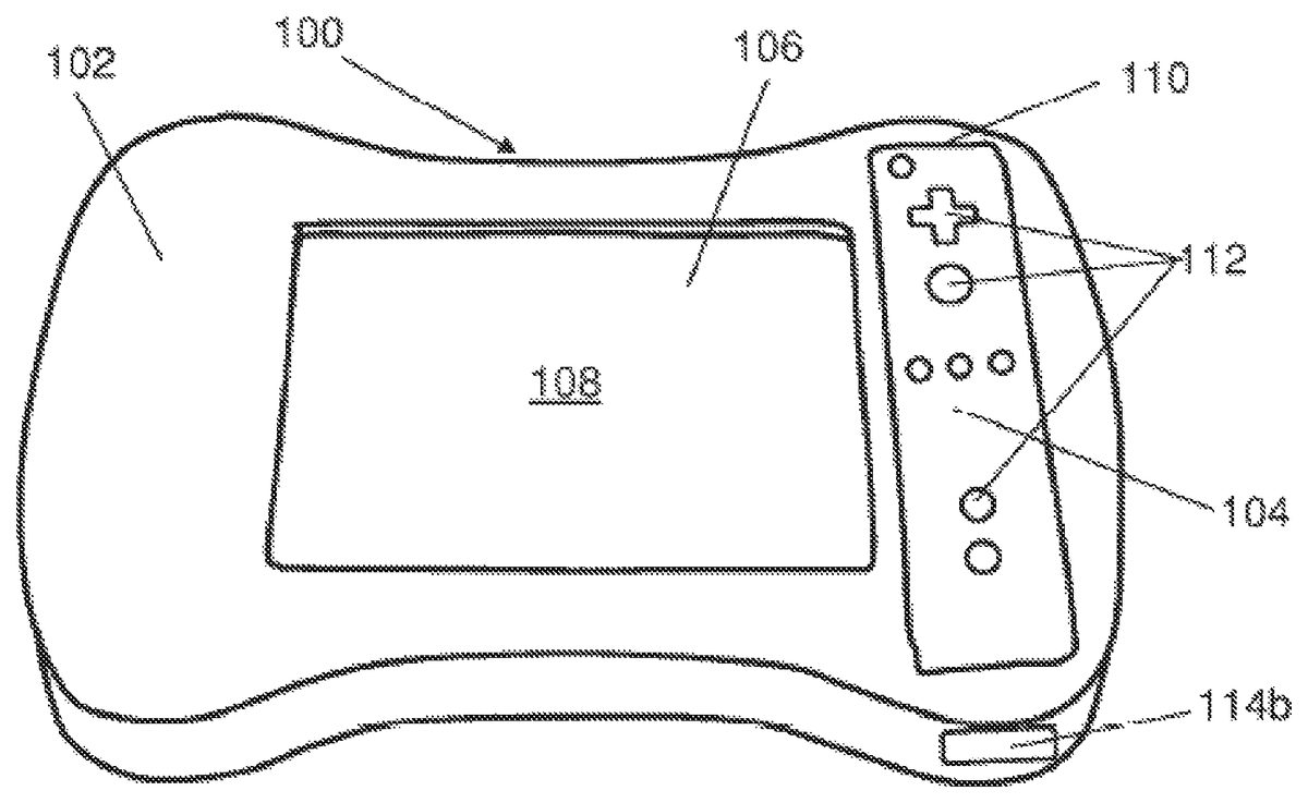
Referring toFIG. 4, in some implementations, a game controller100includes a first control unit102having a second control unit104inserted within. This game controller is designed to be integrated into a game system similar to those presented inFIGS. 2 and 3.
In some examples, the first control unit102includes a display106, an LCD screen for example, enabling the display of information and/or images relating to the game in progress. This LCD screen is overlaid with a touch screen108capable of detecting tactile commands in the form of a sequence of locations touched on the screen. These commands make it possible to modify the displayed information and/or images. The first control unit102also includes a recess110designed to accommodate the second control unit104. Advantageously, the first control unit includes only the touch screen as a control member for direct interaction with the flow of the game and hence with the displayed information and/or images.
The second control unit104is a unit similar to that illustrated inFIG. 1. This control unit104is equipped with an accelerometer and/or with tilt sensors (not shown). An electrical connection (138,FIG. 6;140,FIG. 1) between the two control units is provided such that the signals received by the accelerometer and/or the tilt sensors also make it possible to change the information and/or images displayed on the LCD screen. The recess110of the first control unit is made on the face bearing the display106, so that control buttons112of the second control unit, placed on its upper surface, remain accessible. The control buttons112can be used in the traditional manner.
The signals received from the accelerometer and/or from the tilt sensors via the electrical connection with the second control unit and the tactile commands received via the touch screen are able to simultaneously change the displayed information and/or images. The combination of these two commands, namely detection of the motion of the game controller100and detection of touching performed on the screen108makes it possible to offer a new manner of play that is immersive and interactive, as will be illustrated withFIGS. 9a,9b,9cand10b.
The first control unit102is connected to the game console of the system solely through the second control unit104, which makes it possible to simplify the electronics of the first unit. To this end, the first unit may be connected to the second unit through a connector (140,FIG. 2) already present on the latter. For this purpose there is provided an internal cable (138,FIG. 7) reaching into the recess110. In this manner all the tactile commands can be transmitted to the second unit, then to the console. A manual switch can be provided to operate this functionality.
FIG. 5ashows a side view of the first control unit102. As mentioned previously, the second control unit advantageously includes means of communicating with the video game console, such as for example radio frequency or infrared transmission means. To ensure good transmission between the second control unit and the game console, it is arranged that the first control unit102includes, on one lateral face, an opening114alocated facing the communication means of the second control unit when it is inserted into the recess provided for this purpose.
In some implementations, it is provided that the first control unit be “ambidextrous”, that is usable either by a right-handed or by a left-handed person. To this end, the first control unit102may exhibit a generally symmetrical shape with respect to the LCD screen106. Thus to use the game controller100in a right-handed or left-handed configuration, one need only position the second control unit as shownFIG. 4(right-handed configuration), or inFIG. 6respectively (left-handed configuration).FIG. 5bshows a side view of the first control unit102that is opposite toFIG. 5a. To ensure good transmission between the second control unit and the game console, there is provided on the lateral face opposite that having the opening114aan opening114balso placed facing the communication means of the second control unit when it is inserted in the recess in the left-handed configuration. The openings114aand114bcan be covered with a lens.
Returning toFIG. 6, it therefore shows a reversed view of the second control unit102wherein the second control unit104has been inserted, in the left-handed configuration.
It is also arranged that the touch screen108can be provided with a peripheral frame116capable of holding game boards or grids as shown for example inFIG. 10a. Such a frame makes it possible to change the display that is visible by the player without the need to operate the display of the first control unit; only tactile commands on the touch screen are detected.
FIG. 7shows a bottom view of the first control unit102without the second control unit in its recess110. In this figure, the electrical connection138can be seen for the first unit designed to be connected with the connection (140,FIG. 1) of the second unit, as well as electrical contacts118a(for the right-handed configuration),118b(for the left-handed configuration) placed at the bottom of the recess110to make contact with corresponding contact means (120,FIG. 1) placed on the lower surface of the second unit (104,FIG. 1). Thus, when the second control unit is inserted in the right-handed configuration (FIG. 4), the contacts120of the second unit are in contact with the contacts118aof the first unit, providing power supply to the first unit by the second, the electrical connection between the two control units being provided by the insertion of the connecting element138of the first unit into the corresponding connecting element140of the second unit. The communication means are then arranged facing the lateral opening114a. Likewise, when the second control unit is inserted in the left-handed configuration (FIG. 6), the connecting elements138and140provide the electrical connection between the two control units while the electrical contacts120are in contact with the corresponding contacts118bof the first unit, providing power supply to the first unit. In this other position, the communication means of the second unit are then arranged facing the lateral opening114b.
To ensure the ambidextrous nature of the first control unit, it is provided that the display106is reversible. The electrical contacts118a,118bare then used as detectors for automatically detecting the insertion orientation of the control unit. Indeed, the contacts118aor118brespectively making contact with the corresponding contacts120of the second unit depending on the configuration used, enabling the determination of the insertion orientation of the second unit and to appropriately control the inversion of the display if necessary.
FIG. 8shows the first control unit102equipped with an accessory122. For this purpose, the first unit102includes a hollow recess124(see alsoFIG. 7), or alternatively a projecting plug, capable of receiving an accessory122so as to form an immersive assembly126, as for example a guitar. It is arranged to provide the plug124with electrical connection with the accessory122so as to further increase the play possibilities with the game controller constituted by the two assembled control units102and104. Thus for example the accessory122, in the form of a handle, can include control buttons128making it possible to simulate the pressure of fingers on strings, while the LCD screen106will display the strings of the guitar and will detect through the touch-screen overlying it the player's strumming commands, and the second unit will be used to detect the motions of the player and to display them for example on the central screen connected to the console (not shown). More generally, it will be understood that the plug provided makes it possible to design an accessory for it to transform the appearance of the game controller and make it more immersive.
FIGS. 9a,9band9cshow a sequence of information and images displayed on the display106of the first control unit according to one interactive and immersive game example.FIG. 9ashows the selection of starting scenery134which can be obtained by any kind of command including tactile commands. Thereafter, the player can personalize the game by using personal images130showing for example his own car and his own face. He can also insert personalized dialogs132. In the remainder of the game's flow, the user can use either tactile commands of the first control unit or the acceleration commands of the second control unit, or the two simultaneously, to change the display. Thus for example he can use his fingers on the touch screen to move his character or to change the dialogs in a pre-programmed list of dialogs.FIG. 9cshows a modified display whereon the character and his car130have moved so as to arrive at their destination. The movement between the initial scenery134(FIGS. 9a,9b), showing a road, and the destination scenery136(FIG. 9c), showing a train station, can for example be carried out by signals received from the accelerometer of the second unit allowing the character and his car130to travel over a road circuit (image sequence not shown) connecting the departure and arrival scenery. During the movement carried out by using the game controller as a steering wheel, the player can be led to touch the screen to carry out additional actions provided in the game flow, such as for example to blow the horn by pressing twice on the touch screen, operating his turn signal by sliding his finger to the right or left on the screen, etc.
FIGS. 10aand10bshow the display of the first control unit according to two other game examples.FIG. 10ashows an example wherein a piano game board has been inserted into the frame shown inFIG. 6. At the same time, a piano simulation game is launched on the console enabling interpretation of the tactile commands received on the touch screen. Detection of the force and duration of finger contact on the piano keys can advantageously be provided to faithfully reproduce the sound that the same touch would have caused on a real piano.FIG. 10bshows an arcade game implementing snowmen behind which the characters can take shelter. The player for example will need, through tactile commands, to throw snowballs to hit the characters; likewise he can use sensors from the second unit to avoid snowballs thrown at him by another player.
Having presented the invention above by means of a few examples, it will be understood that the game controller resulting from the assembly of the two control units offers a large number of possibilities for the player in terms of immersion and interaction. In particular, the integration of a touch screen on the first unit provides great flexibility in addition to the possibilities offered by the acceleration or tilt sensors present on the second unit. The combination allows accurate control of the pointers and of the characters. It will also be understood that the use of such a controller proves to be very intuitive and that players have commands that are easy to use.
Among other applications that can be contemplated for such a controller can be mentioned painting, drawing, image and video processing, the creation of personalized animation that can be included in a dedicated game, word processing, and Internet navigation. This controller also proves to be well suited to educational games with the possible use of a stylus. Thus for example the program can ask for words to be entered and associate them with images shown on screen, to complete words by filling in missing letters, to form letters by using a special stylus. The program can also pronounce each letter and the word formed by the letters to help in teaching sounds. The program can also read stories while allowing the player to interact with the story by pressing on the touch screen or to immerse himself by using the commands of the second unit. The player can also personalize the characters and add them to the story with their own names (seeFIGS. 9a,9b,9c), as well as the audio environment by adding music and sound effects of their creations and thus create their true animated story. Specific game grids can be set in the frame provided for this purpose for the different parts of the game or the story. It is understood that such a controller has the advantage of helping children to intuitively develop coordination between their hand and their eyes, as well as to develop their creativity.
As has often been mentioned, such a game controller advantageously makes it possible to take advantage of two commands, one tactile and the other by motion detection, to provide games with an immersive and interactive interface. For example, a maze game wherein the player must move a ball by moving the game controller which applies the motions performed and detected thanks to the sensors of the second control unit, while still at the same time avoiding traps, by using tactile screen tapping or rubbing commands at designated places, or even drawing something that allows him to avoid the trap that is set, for example a bridge to cross a river and thus progress within the maze.
It can finally be noted that such a game controller is particularly suited for network games for which certain information and/or images must be displayed only for the player concerned through his controller and where other information and/or images are displayed so as to be visible to all players on the central screen of the game system.
It will be understood that various modifications and/or improvements that are obvious to the person skilled in the art can be applied to the different embodiments of the invention described in the present description without departing from the scope of the invention defined by the appended claims. Accordingly, other implementations are within the scope of the following claims.
Claims
- A control unit for a home video game console, the control unit comprising: a control unit body;a display supported by the control unit body for displaying information or images relating to the game;and a recess defined by the control unit body for accommodating a second control unit equipped with at least one of an accelerometer or tilt sensors, the recess having an electrical connection between the two control units, wherein the displayed information or images are changed in response to signals received by the accelerometer or the tilt sensors and transmitted to the display through the electrical connection, and a touch screen overlying at least partially over the display wherein the touch screen detecting tactile commands includes a sequence of locations touched on the screen able to change the displayed information and/or images.
- The control unit of claim 1 , wherein the changed information or images are transmitted through the electrical connection to the second control unit having a communicator for communicating with the video game console.
- The control unit of claim 1 , wherein the signals received from the accelerometer or the tilt sensors through the electrical connection with the second control unit and the tactile commands received via the touch screen are able to simultaneously change the displayed information and/or images.
- The control unit of claim 1 , wherein a power supply is provided by the second control unit via electrical contacts.
- The control unit of claim 1 , wherein the touch screen is the sole control member of the control unit for direct interaction with the displayed information or images.
- The control unit of claim 5 , wherein the recess is arranged on the face bearing the display, wherein control buttons of the second control unit are accessible and an opening is made in a lateral face facing the communicator of the second control unit when it is inserted into the recess.
- The control unit of claim 1 , wherein the display is reversible and wherein the recess receives the second control unit in two reversed positions and includes a detector for detecting the insertion orientation of the second control unit for controlling the reversal of the display.
- The control unit of claim 7 , wherein the detector automatically detects the orientation of the second control unit by the electrical power supply contacts placed at the bottom of the recess.
- The control unit of claim 1 , wherein the touch screen includes a peripheral frame arranged for holding game grids.
- The control unit of claim 1 , wherein the control unit body defines a second recess for receiving an accessory to constitute an immersive assembly.
- The control unit of claim 10 , wherein the second recess includes an electrical connection for connecting with the accessory.
- The control unit of claim 1 , wherein the body further includes a second recess defined by the control unit body for receiving an accessory to constitute an immersive assembly.
- A game controller comprising: a first control unit comprising: a control unit body;a display supported by the control unit body for displaying information or images relating to the game;and a recess defined by the control unit body for accommodating a second control unit equipped with at least one of an accelerometer or tilt sensors, the recess having an electrical connection between the two control units, wherein the displayed information or images are changed in response to signals received by the accelerometer or the tilt sensors and transmitted to the display through the electrical connection, and a touch screen overlying at least partially over the display wherein the touch screen detecting tactile commands including a sequence of locations touched on the screen able to change the displayed information or images;and a second control unit insertable into the recess in the first control unit and connectable to the first control unit via the electrical connection in the recess, the second control unit having at least one of an accelerometer or tilt sensors, and a communicator for communicating with the video game console.
- The game controller of claim 13 , wherein the first control unit includes the touch screen as the sole control member for direct interaction with the displayed information or images and wherein the second control unit includes control buttons that are accessible through an opening in the recess.
- The control unit of claim 13 , wherein the display is reversible and wherein the recess receives the second control unit in two reversed positions and includes a detector for detecting the insertion orientation of the second control unit for controlling the reversal of the display means.
- A game system comprising: a home video game console;a central display device;and at least two game controllers, wherein each game controller comprises: a display supported by the control unit body for displaying information and/or images relating to the game;and a recess defined by the control unit body for accommodating a second control unit equipped with at least one of an accelerometer or tilt sensors, the recess having an electrical connection between the two control units, wherein the displayed information or images are changed in response to signals received by the accelerometer or the tilt sensors and transmitted to the display through the electrical connection, and a touch screen overlying at least partially over the display wherein the touch screen detecting tactile commands including a sequence of locations touched on the screen able to change the displayed information or images;and each game controller is usable in a network with other game controllers connected to the console, the display device displaying information or images relating to the game, shared between the different game controllers and the display of each game controller arranged for displaying information or images relating to the game and personalized information and/or images.
- The game system of claim 16 , wherein the personalized information or images change simultaneously in response to the signals received from the accelerometer or the tilt sensors and/or in response to the tactile commands received from the touch screen of the corresponding game controller.
- The control unit of claim 15 , wherein the detector automatically detects the orientation of the second control unit by the electrical power supply contacts placed at the bottom of the recess.
- The control unit of claim 16 , wherein the display is reversible and wherein the recess receives the second control unit in two reversed positions and includes a detector for detecting the insertion orientation of the second control unit acting as means for controlling the reversal of the display means.
- The control unit of claim 19 , wherein the detector automatically detects the orientation of the second control unit by the electrical power supply contacts placed at the bottom of the recess.
Disclaimer: Data collected from the USPTO and may be malformed, incomplete, and/or otherwise inaccurate.