U.S. Pat. No. 8,491,388
GAME SYSTEM AND GAME CONTROLLER
AssigneeSony Corporation; Sony Computer Entertainment Inc.
Issue DateNovember 14, 2008
Illustrative Figure
Abstract
A controller includes at least one vibrator and a vibration control unit which converts an operation input signal which is input to a predetermined operation button into a vibration control signal so as to be supplied to a vibrator. A motion sensor in a sensor unit detects vibration caused by the drive of the vibrator. Sensor output signal value obtained as a result of the detection by the sensor unit is transmitted from a wireless communication module to a game device. A game device achieves a function of automatically firing in succession in a game, based on the sensor output signal value.
Description
DETAILED DESCRIPTION OF THE INVENTION The invention will now be described by reference to the preferred embodiments. This does not intend to limit the scope of the present invention, but to exemplify the invention. FIG. 1shows a use environment of a game system according to an exemplary embodiment of the present invention. A game system1includes an image display unit3, an audio output unit4, a game device10, and a controller20. The image display unit3, the audio output unit4, and the controller20are connected to the game device10. The image display unit3is a display for outputting image signals. The image display unit3receives image signals generated by the game device10, and displays a game screen. The audio output unit4, which are speakers for outputting sound, receives audio signals generated by the game device10, and outputs game audio. The image display unit3and the audio output unit4constitute an output apparatus of the game system1. The game device10and the image display unit3may be connected via wire, such as AV cables, or wireless to each other. Also, a home network using network (LAN) cables or a wireless LAN may be formed between the game device10and the output apparatus. The controller20is an input device where operation data of a game for a user to operate characters in the game are inputted. The game device10is a processor unit which processes game applications based on game operation data supplied from the controller20and generates image signals and audio signals representing the processing result of the game applications and audio signals. The game device10uses the output signal of a motion sensor supplied from the controller20as the game operation data, and also has a function of processing the game applications. The technique described in the present exemplary embodiment can be realized by an entertainment system for executing not only a game application but also ...
DETAILED DESCRIPTION OF THE INVENTION
The invention will now be described by reference to the preferred embodiments. This does not intend to limit the scope of the present invention, but to exemplify the invention.
FIG. 1shows a use environment of a game system according to an exemplary embodiment of the present invention. A game system1includes an image display unit3, an audio output unit4, a game device10, and a controller20. The image display unit3, the audio output unit4, and the controller20are connected to the game device10.
The image display unit3is a display for outputting image signals. The image display unit3receives image signals generated by the game device10, and displays a game screen. The audio output unit4, which are speakers for outputting sound, receives audio signals generated by the game device10, and outputs game audio. The image display unit3and the audio output unit4constitute an output apparatus of the game system1. The game device10and the image display unit3may be connected via wire, such as AV cables, or wireless to each other. Also, a home network using network (LAN) cables or a wireless LAN may be formed between the game device10and the output apparatus.
The controller20is an input device where operation data of a game for a user to operate characters in the game are inputted. The game device10is a processor unit which processes game applications based on game operation data supplied from the controller20and generates image signals and audio signals representing the processing result of the game applications and audio signals. The game device10uses the output signal of a motion sensor supplied from the controller20as the game operation data, and also has a function of processing the game applications. The technique described in the present exemplary embodiment can be realized by an entertainment system for executing not only a game application but also other kinds of applications. A description is given hereinbelow of the game system1, which executes a game application, representing the entertainment system.
The controller20has a function of transmitting the game operation data to the game device10. In the present exemplary embodiment, the controller20is structured as a wireless controller capable of performing wireless communication with the game device10. The controller20and the game device10may establish wireless communication therebetween using Bluetooth (registered trademark) protocol. In the transmission and reception of the game operation data, the game device10functions as a base unit, namely a master unit, whereas the controller20functions as a handset, namely a slave unit. It is to be noted here that the controller20is not limited to a wireless controller but may be a wired controller connected to the game device10through a cable.
The controller20is powered by battery (not shown) and is structured by including a plurality of buttons and keys for effecting game inputs to perform a game. When the user operates such buttons and keys on the controller20, the operation input signals are periodically transmitted wirelessly to the game device10. Also, the controller20is structured by including a 3-axis acceleration sensor for detecting the acceleration of the controller20in the 3-axis directions and an angular velocity sensor for detecting the angular velocity around a predetermined axis. The 3-axis acceleration sensor and the angular velocity sensor constitute a sensor that detects the motion of the controller20. The value detected by each sensor is periodically transmitted wirelessly to the game device10, and those detected values are handled as game operation data according to the progress of a game. For example, in a racing game where the controller20is used as a steering wheel of a vehicle and the user moves the vehicle in the game by moving the controller20operating as the steering wheel, the output signal values of the 3-axis acceleration sensor and the angular velocity sensor are utilized as the game operation data.
The game device10receives the game operation data on the game application from the controller20, controls the progress of the game according to the game operation data, and generates game image signals and game audio signals. The game image signals and game audio signals thus generated are outputted from the image display unit3and the audio output unit4, respectively.
In the game systems of recent years, a game controller having a vibrator such as a motor has been in wide use. Driving the vibrator in accordance with the state of a game character gives a virtual sense of reality to the user, which in turn is effective in enhancing the charm of the game. In the game system1according to the present exemplary embodiment, the controller20is provided with vibrators. The motion sensor detects the vibration of the vibrators caused by the drive of the vibrators, and the values detected by the motion sensor are utilized as the game operation data. This achieves the operation input data to the game device10not found in the conventional practice.
The controller20has a function of generating vibration control signals, with which to vibrate the controller20itself, according to the button operation by the user. The controller20converts an operation input signal which is input to the button into a vibration control signal so as to be supplied to the vibrators. While the user keeps pressing down on a predetermined button, the vibration control signal continues to be produced and these signals may be supplied to the vibrators. When a predetermined button of the controller20is depressed, the controller may supply a vibration start signal to the vibrators so as to derive the vibrators. When pressing down on the predetermined button has been completed, namely, when the predetermined button is released, the controller20may supply a vibration stop signal to the vibrators so as to stop the drive of the vibrators.
The game device10may have a function of transmitting the vibration control signal, with which to vibrate the vibrators, to the controller20according to the progress of a game application or the button operation by the user. Upon receiving the vibration start signal, the controller20drives the vibrators; and upon receiving the vibration stop signal, the controller20stops the drive of the vibrators. It is to be noted that the game device10may transmit, for each transmission frame, the vibration control signal specifying whether the vibrator is to be driven or not. In such a case, the controller20operates based on this control vibration signal. It is to be noted that the vibration control signal supplied to the vibrator in the controller20may be a pulse width modulation (PWM) signal or the like which is a different kind of signal from the vibration control signal supplied from the game device10.
FIG. 2shows an external structure of the controller20. The controller20is provided with a direction key21, analog sticks27, and four kinds of operation buttons26. The four kinds of buttons22to25are distinguished from one another by the marking of different symbols of different colors. That is, the “∘” (circle) button22is marked with a red circle, the “x” (cross) button23with a blue cross, the “□” (square) button24with a purple square, and the “Δ” (triangle) button25with a green triangle.
The user operates the controller20by holding a left-hand grip28awith the left hand and a right-hand grip28bwith the right hand. The direction key21, the analog sticks27, and the operation buttons26are provided on a top surface30of a casing so that the user holding the left-hand grip28aand the right-hand grip28bcan operate them.
Disposed in each of the casings of the left-hand grip28aand the right-hand grip28bis a vibrator, which is constituted by a motor and other parts. The left and right vibrators are driven with the supply of a vibration control signal instructing drive, and the vibration is communicated to the casing of the controller20, which vibrates accordingly. Also, disposed near the center within the casing of the controller20is a board which controls the motion of the controller20. Provided on this board are the aforementioned 3-axis acceleration sensor, angular velocity sensor, and the like. Note also that the casing forming the shell of the controller20is structured by a top casing and a bottom casing, which are fitted to each other, and that the vibrators and the board are fixed to the bottom casing.
The motion sensors, such as a 3-axis acceleration sensor and an angular velocity sensor, on the board not only detect the motion of the controller20, but also detect the vibration of the controller20which may occur as the vibrators are driven. In the game system1according to the present exemplary embodiment, the vibration of the controller20detected by the motion sensors along with the drive of the vibrators is processed as part of operation data for a game. As a result, the vibration of the controller20itself may be utilized as operation input signals to a game while the user feels the vibration thereof as he or she operates it. A predetermined button of the controller20may be assigned to function as a switch for generating a vibration control signal for driving the vibrators, and at the same time the detected values of motion sensors detecting the vibration of the controller20may be utilized as operation input signals in an automatic fire mode of the game, for instance. Thus, the user can enjoy a game with a greater sense of reality as he or she feels the vibration while effecting an automatic fire in the game.
FIG. 3shows an external structure of the back side of the controller20. As viewed from the back side of the casing, the direction key21is provided at an upper right position of the casing, and the operation button26at an upper left position thereof. Also, two analog sticks27are provided in positions between the direction key21and the operation button26. Provided in the middle part of a casing back29is a USB connector46. A USB cable leading from the game device10is connected to the USB connector46, which allows a charging of the controller20. It is to be noted that with the USB cable connected, the controller20may be used as a wired controller as well.
On the casing back29side, an upper operation button32a, an upper operation button32b, a lower operation button34a, and a lower operation button34bare provided in their respective right-left longitudinal symmetrical positions of the casing back29. The upper operation button32aand the upper operation button32bare positioned such that they can be operated with the tips of the forefingers of the left and right hands respectively of the user holding the left-hand grip28aand the right-hand grip28b. And the lower operation button34aand the lower operation button34bare positioned such that they can be operated with the tips of the middle fingers of the user's left and right hands, respectively.
The upper operation button32aand the upper operation button32bare formed as pushbuttons. An input from either one of or both of the upper operation buttons32aand32b, which is effected by a press of the button, becomes an on-off digital input signal. On the other hand, the lower operation button34aand the lower operation button34bare formed as trigger buttons which are supported rotatably. The lower operation buttons34aand34b, which are each a rotatable input interface, produce an analog input signal corresponding to the amount of rotation. It is to be noted that the upper operation buttons32aand32bmay also be formed as an input interface capable of producing analog input signals. The lower operation buttons34aand34bare each supported rotatably by a rotating shaft and biased toward the outside of the casing by a spring or the like. As a result, unless pressed by the user, the lower operation buttons34aand34bremain in their respective positions, biased in the direction away from the casing. Hereinafter, “upper operation button32” and “lower operation button34” indicate either one of or both of “upper operation buttons32aand32b” and either one of or both of “lower operation buttons34aand34b”, respectively.
In the controller20, the lower operation buttons34aand34bare each supported rotatably by a rotating shaft which is disposed substantially parallel to the longitudinal direction of the casing back29. The lower operation buttons34aand34bare each supported rotatably in the upper portion thereof, so that a press on the lower portion of the surface of the lower operation buttons34aand34bby the user causes the lower operation buttons34aand34bto be turned inward into the casing. Formed at the lower end of the surface of the lower operation buttons34is a projection protruding in a direction away from the rotating shaft, or more specifically downward or diagonally downward. Therefore, the projection is disposed on the side of the casing back with respect to the rotating shaft.
A capacitance type sensor may be employed as a means for detecting the amount of rotation of the lower operation button34. The capacitance type sensor can detect the amount of rotation of the lower operation button34by detecting the change in capacitance between two electrodes. Thus, a means for detecting the capacitance between the electrodes as an analog value is provided in the controller20, and the analog value obtained by the detecting means is converted into a digital value corresponding to the amount of rotation. In this manner, the controller20can obtain an input signal value corresponding to the amount of rotation.
In another example, a sensor for detecting resistance change may be employed as a means for detecting the amount of rotation of the lower operation button34. For example, a circuit pattern conducting electricity between two terminals at a predetermined resistance may be provided in the casing, and a conductive rubber may be provided at the end of the turning direction of the lower operation button34. As the lower operation button34is turned, the conductive rubber provided at the end of the turning direction comes into contact with the circuit pattern inside the casing. The conductive rubber is formed deformably so that the area of contact thereof with the circuit pattern changes with the amount of rotation, thus changing the resistance value between the two terminals according to the amount of rotation. In this manner, the amount of rotation can be detected by detecting the above-mentioned resistance value, and the controller20can obtain an input signal value corresponding to the amount of rotation.
FIGS. 4A and 4Bshow an external structure of a side of the controller20.FIGS. 4A and 4Bshow a lower operation button34bas viewed from the right-hand side of the controller20, and it is to be noted that a lower operation button34awhich can be seen from the left-hand side has also the same structure.FIG. 4Aillustrates the lower operation button34bin a state not yet turned, andFIG. 4Bthe lower operation button34bhaving been turned fully around a rotating shaft36b. When the lower operation button34bis turned, the projection thereon functions as a stopper by limiting the turning motion as it comes into contact with the external surface of the casing, or more specifically the edge portion of an opening. Note also that, as illustrated, a shell portion of the casing forming the opening may be inclined downward to make the amount of rotation, namely, the stroke of the lower operation button34larger. And larger stroke means a wider range of analog values that can be inputted.
In a game system1according to the present exemplary embodiment, the function of a switch for driving a vibrator provided inside the casing is assigned to the lower operation button34. The lower operation buttons34aand34bmay be assigned to function as switches to drive the vibrators disposed on the left side and right side respectively, but also either one of the lower operation buttons34aand34bmay be assigned to function as a switch to drive both the vibrators.
In the game system1, the vibration frequency of the vibrator or vibrators may be controlled according to the amount of rotation of the lower operation button34. Also, the amplitude of vibration may be controlled as well. As the casing vibrates along with the drive of the vibrator, the motion sensor detects the vibration. In the game system1, the automatic fire function of a game is realized based on the vibration thus detected.
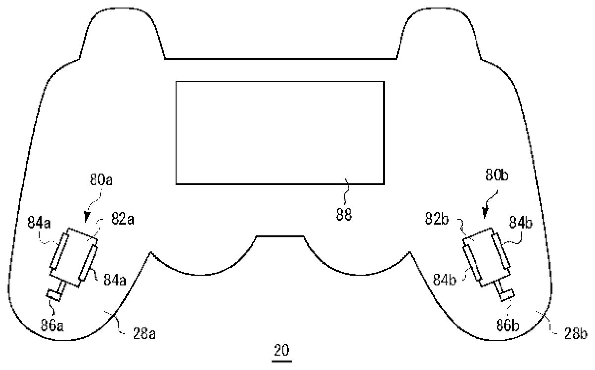
FIG. 5shows an arrangement of a board and vibrators fixed to the bottom casing as they are exposed with the top casing of the controller removed. A board88, which has a horizontally long shape, is fixed in a front center position of the bottom casing. A vibrator80a, which has a motor82aand an eccentric member86aattached to an end of a motor shaft, is fixed to a position of the left-hand grip28aof the bottom casing, held by a pair of clamps84a. Similarly, a vibrator80b, which has a motor82band an eccentric member86b, is fixed to a position of the right-hand grip28bof the bottom casing, held by a pair of clamps84b. The eccentric members86aand86beach having a semicircular shape is fixed to the motor shaft eccentrically and vibrates the casing when the motor shaft rotates. Hereinafter, “vibrator80” indicates either one of or both of “vibrators80aand80b”.
FIG. 6shows an internal structure of the controller20. The controller20includes a processor90, vibrators80aand80b, which are each constituted by a motor and an eccentric member, a wireless communication module72, and a USB connector46. The wireless communication module72has a function of wirelessly transmitting and receiving data to and from a wireless communication module of a game device or game devices10. If one end of a USB cable connected, at the other end thereof, to a USB connector of the game device10is inserted into the USB connector46, then the controller20can perform wired transmission and reception of data to and from the game device10. The processor90carries out processings expected of the controller20. The functions of the processor90and the wireless communication module72may also be realized by circuitry built into the board88provided inside the casing.
The processor90includes a main control unit50, an input receiving unit52, a sensor unit58, an analog-to-digital conversion unit62, a memory64, a read-out unit66, a communication control unit68, and a vibration control unit70. The communication control unit68sends and receives necessary data to and from the wireless communication module72. The following description is about a case where a wireless communication takes place between the controller20and the game device10. However, note that communication may take place between the controller20and the game device10by the use of a USB cable also.
The input receiving unit52receives operation input signals from input units, such as the direction key21, operation buttons26, analog sticks27, upper operation buttons32, and the like, and sends them to the main control unit50. The main control unit50supplies the received operation input signal to the memory64where it is stored. The operation input signal values from the respective input units are stored by overwriting in the respectively assigned areas of the memory64.
The communication control unit68controls the transmission processing by the wireless communication module72with a predetermined period. Since the frame period of game image for the game device10is set at 1/60 seconds, the transmission period of the wireless communication module72is set to a period of 1/60 seconds or shorter, for instance, 11.25 ms. The read-out unit66reads out data from the memory64in time with the transmission period of the wireless communication module72and supplies the data to the communication control unit68. Since the operation input values from the respective input units are stored by overwriting in their respective memory areas, the read-out unit66can supply the latest game operation data to the communication control unit68.
The sensor unit58includes an acceleration sensor54and an angular velocity sensor56. Where the sensor unit58is to include a 3-axis acceleration sensor, the sensor unit58is constituted by including three acceleration sensors54. The acceleration sensor54detects the motion of the controller20in a predetermined axial direction, whereas the angular velocity sensor56detects the motion of the controller20around a predetermined axis. In the present exemplary embodiment, as the acceleration sensor54and/or the angular velocity sensor56detect the vibration of the controller20along with the drive of the vibrator80, the detected value is utilized as game operation data for the game application, for example, for the execution of the automatic fire function.
The analog-to-digital conversion unit62includes a plurality of analog-to-digital converters (ADCs)60. Each of the ADCs60converts analog signals outputted from the sensor unit58to digital signals. The sampling period is preferably set shorter than the transmission period of the wireless communication module72; it may, for instance, be about 2 ms. Also, the analog-to-digital conversion unit62may keep a fixed sampling period, and the sampling period may be controlled desirably by the main control unit50. The ADCs60overwrite sampled values in their assigned areas of the memory64.
As already described above, the read-out unit66reads out data from the memory64in time with a specific transmission period of the wireless communication module72and supplies the data to the communication control unit68. Since the sensor output signal values supplied from the respective ADCs60are stored by overwriting in their respective memory areas, the read-out unit66can supply the latest sensor output signal value to the communication control unit68. The communication control unit68has the wireless communication module72transmit sensor output signals obtained by the motion sensors, such as the acceleration sensor54and the angular velocity sensor56, together with operation values from the operation buttons26and the like received by the input receiving unit52, as game operation data to the game device10.
In the controller20of the present exemplary embodiment, the input receiving unit52sends operation input signals from the lower operation buttons34aand34b, as soon as it receives the input signals, to the vibration control unit70. In this exemplary embodiment, the lower operation buttons34aand34bare the buttons for driving the vibrator80by producing analog input signals corresponding to the amount of operation, namely, the amount of rotation, by the user. The vibration control unit70converts the received operation values into vibration control signals and supplies them to the vibrator80.
The vibration control unit70has a function of determining the vibration frequency of the vibrator80according to the amount of operation of the lower operation button34. The vibration control unit70produces vibration control signals such that the greater the amount of operation thereof, the higher the vibration frequency of the vibrator80will be, and the smaller the amount of operation thereof, the lower the vibration frequency of the vibrator80will be.
FIG. 7Ashows a relationship between the amount of operation of an operation button and the drive voltage supplied to a vibrator. The vibration frequency of the vibrator80can be raised by so arranging that the greater the amount of operation of the operation button34, the higher the drive voltage supplied to the vibrator80will be. Hence, the farther the user pushes the lower operation button34, the higher the vibration frequency will be at which the vibrator80is driven, thus increasing the vibration of the controller20.
Also, the vibration control unit70may have a function of determining the vibration amplitude of the vibrator80according to the amount of operation of the lower operation button34. For example, the vibration control unit70may determine the vibration amplitude of the vibrator80by adjusting the duty ratio of vibration control signals to be supplied to the vibrator80. The vibration control unit70may produce vibration control signals such that the greater the amount of operation of the lower operation button34, the greater the vibration amplitude of the vibrator80will be, and the smaller the amount of operation of the lower operation button34, the smaller the vibration amplitude of the vibrator80will be.
FIG. 7Bshows a relationship between the amount of operation of an operation button and the duty ratio of PWM signals supplied to a vibrator. The vibration amplitude of the vibrator80can be increased by so arranging that the greater the amount of operation of the operation button34, the higher the duty ratio of vibration control signals supplied to the vibrator80will be. Hence, the farther the user pushes the lower operation button34, the greater the vibration amplitude will be at which the vibrator80is driven, thus increasing the vibration of the controller20.
As described above, the vibration control unit70produces vibration control signals to adjust the vibration frequency and/or vibration amplitude of the vibrator80according to the amount of operation of the lower operation button34and supplies them to the vibrator80. And this causes the controller20to vibrate at the vibration frequency and/or vibration amplitude corresponding to the amount of operation of the lower operation button34, and the user can feel the vibration through his/her hands. At this time, the motion sensor, which comprises an acceleration sensor54and an angular velocity sensor56, detects the vibration of the controller20caused by the drive of the vibrator80. This sensor output signal is sent from the wireless communication module72to the game device10to be utilized as game operation data to execute the automatic fire function.
FIG. 8shows a structure of the game device10. The game device10includes a wireless communication module100, a USB connector101, a communication control unit102, a main control unit104, a game operation data supply unit106, an application processing unit110, and an output unit112. In the present exemplary embodiment, the processing functions of the game device10are realized by the CPU, memory, programs loaded in the memory, and the like, and the exemplary embodiment described herein is implemented through the cooperation therebetween. Such programs may be built into the game device10, or may be ones to be supplied externally from a recording medium where they are stored. Hence, it is understood by those skilled in the art that these function blocks can be realized in a variety of forms such as by hardware only, software only, or the combination thereof. In the example ofFIG. 8, the CPU of the game device10realizes the functions of the communication control unit102, the main control unit104, the game operation data supply unit106, and the application processing unit110. It is also to be noted that the game device10may have a plurality of CPUs for the purpose of hardware configuration. In such a case, one CPU may function as the communication control unit102to control the operation of the wireless communication module100; another CPU may function as the main control unit104to control the overall operation of the game device10; another CPU may function as the application processing unit110to execute a game application; and still another CPU may function as the game operation data supply unit106to supply game operation data to the application processing unit110.
The communication control unit102controls the communication processing by the wireless communication module100by sending and receiving necessary data to and from the wireless communication module100, and the wireless communication module100establishes wireless communication with the wireless communication module72of the controller20. The wireless communication module100and the wireless communication module72establish a connection therebetween by the Bluetooth (registered trademark) protocol, for instance. The wireless communication module72of the controller20transmits data, such as game operation data, with a predetermined period, and the communication control unit102supplies the data received by the wireless communication module100to the main control unit104. Note that in a setup where one end of a USB cable connected, at the other end thereof, to a USB connector46of the controller20is inserted into the USB connector101, the communication control unit102may control the processing of communication with the controller20by way of the USB cable.
The main control unit104supplies the operation input values and sensor output signal values supplied from the controller20to the game operation data supply unit106. The game operation data supply unit106converts the received operation input values and sensor output values into game operation data and supplies them to the application processing unit110. When there is a predetermined operation input from the user, the game operation data supply unit106may carry out a processing to produce game operation data for the automatic fire mode. For example, the arrangement may be such that both the shifting to and ending of the automatic fire mode are effected by a simultaneous press on the two lower operation buttons34aand34bby the user and that the game operation data supply unit106determines the timing for producing game operation data for the automatic fire mode upon detecting the simultaneous press on the lower operation buttons34aand34b. The application processing unit110has the game operation data received from the game operation data supply unit106reflected in the processing of the game application. In other words, the application processing unit110executes the automatic fire mode in a game, using the game operation data corresponding to the sensor output values.
FIG. 9shows the output signal of a sensor detecting the motion of a controller caused by the drive of the vibrator. This sensor output signal may be an acceleration sensor output signal of the Z-axis component (vertical component), or may be an acceleration sensor output signal of another axis component, or may even be an angular velocity sensor output signal.FIG. 9Ashows a sensor output signal when the vibrator is driven at low vibration frequency, whereasFIG. 9Bshows a sensor output signal when the vibrator is driven at relatively high vibration frequency. The game operation data supply unit106converts this sensor output signal value into game operation data and supplies them to the application processing unit110.
The game operation data supply unit106may determine the number of virtual bullets to be fired per unit time in the automatic fire mode, for instance, by measuring the sensor output period and may supply the information as game operation data to the application processing unit110. A short sensor output period means the drive of the vibrator80at a high vibration frequency. However, by vibrating the controller20violently and at the same time increasing the number of bullets fired per unit time in automatic fire in the game, it is possible to have the user experience bodily the relationship between the vibration of the controller20and the number of bullets fired. That is, in this case, the higher the vibration frequency of the controller20is, the greater the number of bullets fired by a game character is, so that the user can virtually experience a violent firing of bullets.
Also, the game operation data supply unit106may determine the number of virtual bullets to be fired per unit time in the automatic fire mode by measuring the sensor output amplitude and may supply the information as game operation data to the application processing unit110. A large sensor output amplitude means a large motion of the controller20. However, by vibrating the controller20largely and at the same time increasing the number of bullets fired per unit time in automatic fire in the game, it is possible to have the user experience bodily the relationship between the vibration of the controller20and the number of bullets fired. That is, in this case, the greater the number of bullets fired by a game character is, the larger the vibration amplitude of the controller20is, so that the user can virtually experience a violent firing of bullets.
Note also that the game operation data supply unit106may determine the flying distance of bullets by measuring the sensor output amplitude. That is, it can make the flying distance of bullets longer if the amplitude of sensor output signal is large or shorter if it is small. This allows the user to bodily experience the relationship between the vibration of the controller20and the flying distance of bullets. It is also to be noted that the game operation data supply unit106may determine the number of virtual bullets to be fired per unit time based on the sensor output period and at the same time may determine the flying distance of bullets by the amplitude of sensor output signal.
FIG. 10shows a concrete example of output signals of a sensor detecting the motion of a controller caused by the vibration of vibrators. These sensor output signals represent acceleration sensor output signals of the X-axis component transmitted every 10 milliseconds.FIG. 11shows in a curved line the sensor output signals shown inFIG. 10plotted on the time axis.
The game operation data supply unit106may set a reference value for sensor output signal. And the game operation data supply unit106may supply game operation data for firing a virtual bullet to the application processing unit110when it has detected the sensor output signal going above the reference value from a value equal to or below it or when it has detected the sensor output signal going down to or below the reference value from a value above it. The reference value may be a predetermined fixed value, or, as will be described later, it may be set according to the game environment. In the example ofFIG. 10andFIG. 11, the game operation data supply unit106sets the reference value at512, for instance, and produces and supplies game operation data for firing a virtual bullet to the application processing unit110when the sensor output signal has gone above 512. During the period from 0 to 200 ms, the sensor output signal value goes above 512 from a value equal to or below it at 30 ms, 50 ms, 80 ms, 110 ms, 140 ms, 170 ms, and 200 ms. The game operation data supply unit106produces game operation data for firing a virtual bullet when it determines that the sensor output signal has gone above the reference value. Therefore, in this example, a total of seven virtual bullets are fired automatically during the period of 200 milliseconds.
The application processing unit110may perform a processing such that a virtual bullet is fired when it receives game operation data concerning the pressing of a predetermined operation button26by the user. More specifically, the on state (pressed state) and the off state (released state) of the predetermined operation button26are handled as binary signals of “0” and “1” respectively, and the application processing unit110performs a processing to fire a virtual bullet when the state of the operation button26has shifted from the on state to the off state. That is, the application processing unit110performs a processing to fire a virtual bullet when the status value (operation data) of the predetermined operation button26shifts from “0” to “1”. Using this arrangement, the game operation data supply unit106may convert a sensor output signal equal to or below the reference value to “0” and a sensor output signal above the reference value to “1” and may supply the converted value as game operation data to the application processing unit110. After the processing of a converted value of sensor output signal in the same manner as with the status value of the operation button26, the application processing unit110can perform a processing to fire a virtual bullet when the converted value shifts from “0” to “1”. As a result, a virtual bullet is fired when the sensor output signal goes above the reference value from a value equal to or below it, so that it becomes possible to automatically fire a plurality of virtual bullets in succession within a short time.
The game operation data supply unit106may produce game operation data for firing a virtual bullet when the number of times of the sensor output signal going above the reference value has reached a predetermined number of times. The game operation data supply unit106counts the number of times of the sensor output signal going above the reference value and produces game operation data at a rate of once every predetermined number of times. In this manner, the game operation data supply unit106can adjust the automatic firing rate.
The game operation data supply unit106may monitor the operation input values it receives. And when the game operation data supply unit106decides that an operation input of a lower operation button34has occurred after a state without the operation input thereof, it may set the sensor output signal immediately before it as the reference value. In other words, the game operation data supply unit106monitors the content of operation input values, and when it decides that vibration has started with an operation of a lower operation button34, it employs the sensor output signal value immediately before the start of vibration as the reference value. By the use of the sensor output signal value immediately before the start of vibration as reference, it is now possible to acquire sensor output signals swinging above and below the reference value.
Also, upon detecting an operation input of a lower operation button34after a state without the operation input thereof, the game operation data supply unit106may calculate an average value of a predetermined number of sensor output signals thereafter and employ the average value as the reference value. For example, by referring toFIG. 10andFIG. 11, the game operation data supply unit106averages the five sensor output signal values from the start of vibration to 50 ms ((502+512+515+502+514)/5) and sets the average of 509 as the reference value. By obtaining a reference value based on sensor output signal values during vibration, it is possible to set a reference value appropriate for the actual use environment, such as the position and orientation of the controller20and the like.
When the sensor output signals are high or low relative to the set reference value a predetermined number of times consecutively, the game operation data supply unit106may also change the reference value. For instance, the set reference value is deemed too low if the sensor output signals are higher than the reference value ten times consecutively. Hence, the game operation data supply unit106counts the number of times of the sensor outputs being higher or lower than the reference value consecutively and changes the reference value when the number of times has reached a predetermined number of times. The game operation data supply unit106may also reset the reference value by averaging a predetermined number of sensor output signal values or by adding or subtracting a predetermined value to or from the set reference value.
Although it is the acceleration component of the X axis that is shown inFIG. 10andFIG. 11, the game operation data supply unit106may produce game operation data, using the acceleration component of another axis. Also, the game operation data supply unit106may produce game operation data, using the acceleration components of a plurality of axes. For example, the game operation data supply unit106may determine the timing of the reference value being exceeded from the acceleration components of the X axis and Y axis and may produce game operation data when there is a match between the determined timings for both the axes.
The game operation data supply unit106may change the power of a virtual bullet according to the extent of swing from the reference value. For example, when the absolute value of (sensor output signal value−(minus) reference value) is greater than or equal to a predetermined value at the point of producing game operation data, the game operation data supply unit106may produce such game operation data that the power of a virtual bullet is greater than usual.
The application processing unit110produces image signals and audio signals to reflect game operation data in the motions of game characters and sends them from the output unit112to the image display unit3and the audio output unit4, respectively. For instance, the application processing unit110produces image signals and audio signals for automatic fire of virtual bullets in the game from game operation data and supplies them to the image display unit3and the audio output unit4, respectively. In this manner, the application processing unit110produces game image signals and game audio signals to realize the automatic firing rate, travel distance of bullets, and the like adjusted according to the vibration frequency and amplitude of the controller20, thus realizing a new sense of the game world which fuses the actual vibration of the controller20with the automatic firing rate in the game. In such a game, the controller20starts vibrating when an automatic fire starts and stops vibrating when it stops.
The description so far has dealt with processings for a shooting game. In a fight game, on the other hand, sensor outputs may be reflected in the number of punches and/or kicks delivered by a character, the strength of the character's punches, and the like. For example, for shorter periods of sensor outputs, the number of punches and/or kicks may be increased, whereas for longer periods of sensor outputs, it may be decreased. At the same time, the strength of punches and/or kicks may be increased for greater amplitudes of sensor outputs and decreased for smaller amplitudes thereof.
In the exemplary embodiment described so far, the switch function for driving the vibrators80is assigned to the lower operation buttons34. However, this assignment may be controlled by the game device10. For example, when it is ready for an automatic fire in a game, the game device10may set the input and output paths within the controller20such that operation input signals which are input to the lower operation buttons34are supplied directly to the vibration control unit70. When an automatic fire cannot be effected in the game, operation input signals which are input to the lower operation buttons34are handled the same way as operation input signals to the other operation buttons.
For example, the application processing unit110determines whether the automatic fire function is usable or not based on the progress of an application, and when it is usable, performs a control to connect a path from the lower operation buttons34on the controller20to the vibration control unit70. And when the automatic fire function is not used, the application processing unit110cuts off the path from the lower operation buttons34to the vibration control unit70. The controller20has multiple types of register maps defining the connection paths of the operation buttons, and a path control is performed at the controller20when the application processing unit110instructs a switching of the register maps to the main control unit50of the controller20.
In this manner, the game device10recognizes whether automatic fire is possible or not, so that the game operation data supply unit106can use sensor output signal values sent during a period when auto fire is possible as input signals for automatic fire. On the other hand, the game operation data supply unit106may discard the sensor output signal values sent during the period when the automatic fire mode is off.
The present invention has been described in conjunction with the exemplary embodiments. These exemplary embodiments are given solely by way of illustration. It will be understood by those skilled in the art that various modifications to the combination of each component and each process thereof are possible and that such modifications are also within the scope of the present invention. For example, though a description has been given of a case where there are two vibrators80aand80bin the exemplary embodiments, the number of vibrators80may be one or three or more.
The vibration of the controller20is effected according to the amount of operation of the lower operation button34. However, the arrangement may be such that the vibration of the controller20reaches its maximum at a position where the press on the lower operation button34is not at its maximum. For example, a vibration frequency equal to the natural frequency of the controller20may be set at the middle point of pressing on the lower operation button34, which will result in an arrangement where a maximum vibration is obtained when the user presses the lower operation button34to the middle point.
FIG. 12shows a variation of the structure of the game device10. In the exemplary embodiments so far described, drive control signals are produced within the controller20. However, the game device10as shown inFIG. 12has a function of producing drive control signals from operation input values sent from the controller20. The structure of the game device10ofFIG. 12differs from that of the game device10as shown inFIG. 8in that it includes a vibration control signal generator108for producing vibration control signals.
The application processing unit110, upon receiving operation input values on a predetermined operation button from the game operation data supply unit106, instructs the vibration control signal generator108to produce a vibration control signal. This predetermined operation button is a button assigned as the switch to drive the vibrator80by the application processing unit110, which may, for instance, be a lower operation button34capable of effecting an analog input signal. In this modification, the operation input signal which is input to the lower operation button34at the controller20is transmitted from the wireless communication module72to the game device10together with operation input signal on the other operation buttons. The operation input signal on the lower operation button34is supplied to the application processing unit110by way of the wireless communication module100, the communication control unit102, the main control unit104, and the game operation data supply unit106.
The vibration control signal generator108produces a vibration control signal according to the instruction from the application processing unit110and supplies it to the main control unit104. Upon receiving the vibration control signal from the main control unit104, the communication control unit102has the vibration control signal transmitted from the wireless communication module100to the controller20.
At the controller20, the main control unit50, upon receiving the vibration control signal, supplies it to the vibration control unit70. In this modification, therefore, the vibration control unit70, which does not produce vibration control signals on its own, drives the vibrator80by utilizing the vibration control signal sent from the game device10. As explained with the exemplary embodiments, the sensor output signal value detected by the motion sensor is transmitted periodically from the wireless communication module72to the game device10. While the vibration control signal generator108is generating a vibration control signal to drive the vibrator80, the sensor output signal value to be sent is processed as input signals for an automatic fire by the application processing unit110.
FIG. 13shows a filter circuit for filtering the output signal of a motion sensor. The filter circuit92is disposed between a set of an acceleration sensor54and an angular velocity sensor56and an ADC60. The filter circuit92is configured so that an LPF96ahaving a predetermined cutoff frequency and a BPF96bhaving a predetermined passband can be used selectively by a switch94. For example, the arrangement may be such that the LPF96ahas a cutoff frequency of 15 Hz and the BPF96bhas a passband within a predetermined range of 15 Hz or above. Also, the switch94can select a bypass route96cwhich does not pass through the LPF96aand the BPF96b.
When the output signal of the motion sensor in response to the movement of the controller20by the user is utilized as game operation data, the main control unit50has the switch94connect the sensor output to the LPF96a. This happens, for instance, when the controller20is operated on the assumption of it being a steering wheel of a vehicle. In such a case, the vibration frequency given by the user to the controller20is assumed to be about 15 Hz at most, so that the motion of the controller20caused by the action of the user can be extracted properly by filtering the sensor output signal by the LPF96a. It is to be noted that when the vibrator80is not driven, the main control unit50may have the switch94connect the sensor output to the bypass route96c.
On the other hand, when the motion of the controller20caused by the drive of the vibrator80is to be extracted, the main control unit50has the switch94connect the sensor output to the BPF96b. Where the controller20vibrates due to the drive of the vibrator80, the vibration frequency of the controller20is higher than 15 Hz. Therefore, by filtering the sensor output signal by the BPF96b, it is possible to remove the motion component of the controller20caused by the action of the user and thus extract the motion of the controller20caused by the drive of the vibrator80properly.
Claims
- A game system comprising a game controller and a game device for executing a game application, the game controller including: at least one vibrator configured to be driven by a vibration control signal;an operation button configured to be operated by a user;a vibration control unit configured to convert an operation input signal, which is generated by an operation of the operation button, into the vibration control signal so as to be supplied to the at least one vibrator;a motion sensor configured to detect vibration caused by a drive of the at least one vibrator and output an analog signal based on the detected vibration;an analog-to-digital converter configured to analog-to-digital convert the analog signal of the motion sensor into a sensor output signal;and a first communication module configured to supply the sensor output signal, which has been analog-to-digital converted, to the game device, and the game device including: a second communication module configured to receive the sensor output signal from the game controller;an application processing unit configured to carry out a processing of the game application;and a supply unit configured to supply the received sensor output signal to the application processing unit as game operation data, wherein the application processing unit reflects the game operation data received from the supply unit, in the processing of the game application.
- A game system according to claim 1 , wherein the vibration control unit determines vibration frequency or vibration amplitude of the at least one vibrator according to an operation amount of the operation button.
- A game system according to claim 1 , when the sensor output signal going above a reference value from a value equal to or below the reference value is detected or when the sensor output signal going down to or below the reference value from a value above the reference value is detected, the supply unit generates game operation data and supplies the generated game operation data to the application processing unit.
- A game system according to claim 1 , wherein the application processing unit fires virtual bullets in succession, based on the game operation data received from the supply unit.
- A game controller for transmitting game operation data to a game device, the game controller comprising: at least one vibrator configured to be driven by a vibration control signal;a motion sensor configured to detect a motion of the game controller caused by a drive of the at least one vibrator and output an analog signal;an operation button configured to be operated by a user wherein the operation of the operation button drives the at least one vibrator;a vibration control unit configured to convert an operation input signal, which is generated by an operation of the operation button, into the vibration control signal so as to be supplied to the at least one vibrator;an analog-to-digital converter configured to analog-to-digital convert the analog signal of the motion sensor into a sensor output signal;and a communication module configured to supply the sensor output signal, which has been analog-to-digital converted, to the game device in which the sensor output signal is comprised in the game operation data.
- A game system comprising a game controller and a game device for executing a game application, the game controller including: an operation button configured to be operated by a user so as to generate a vibration control signal in the game device;at least one vibrator configured to be driven by the vibration control signal;a motion sensor configured to detect vibration caused by a drive of the at least one vibrator and output an analog signal based on the detected vibration;an analog-to-digital converter configured to analog-to-digital convert the analog signal of the motion sensor into a sensor output signal;and a first communication module configured to supply the sensor output signal, which has been analog-to-digital converted, and an operation input signal, which is generated by an operation of the operation button, to the game device, and the game device including: a second communication module configured to receive the sensor output signal and the operation input signal from the game controller;an application processing unit configured to carry out a processing of a game application;a vibration control signal generator configured to generate the vibration control signal based on the operation input signal received by the second communication module;and a supply unit configured to supply the received sensor output signal to the application processing unit as game operation data, wherein the application processing unit reflects the game operation data received from the supply unit, in the processing of the game application, and wherein the second communication module supplies the generated vibration control signal to the game controller.
- A game system according to claim 6 , when the sensor output signal going above a reference value from a value equal to or below the reference value is detected or when the sensor output signal going down to or below the reference value from a value above the reference value is detected, the supply unit generates and supplies the game operation data to the application processing unit.
- A game system according to claim 6 , wherein the application processing unit fires virtual bullets in succession, based on the game operation data received from the supply unit.
Disclaimer: Data collected from the USPTO and may be malformed, incomplete, and/or otherwise inaccurate.