U.S. Pat. No. 8,491,365
SPORTS VIDEO GAME WITH ENHANCED CONTROL FEATURES
AssigneeNintendo Co., Ltd.
Issue DateOctober 3, 2007
U.S. Patent No. 8,491,365: Sports video game with enhanced control features

Summary:
animation for display that shows the ball flying along a trajectory;
using the at least one processor, based on the further input from the first user, applying a power boost to the ball while it is flying along the trajectory.
Illustrative Figure
Abstract
A battle volleyball or other sports game having both sports and battle game aspects is played between opposing teams. A game object, having at least one associated characteristic, is used in the game. An associated characteristic of the game object is altered based on properly timed player input, the input being timed to coincide with one or more action indicators displayed along a game object movement path. The game object may also negatively affect a health or other game character related parameter of a game character towards which the game object is directed.
Description
DETAILED DESCRIPTION Techniques described herein can be performed on any computer graphics system including a personal computer, a home video game machine, a portable video game machine, a networked server and display, a cellular telephone, a personal digital assistant, or any other type of device or arrangement having computation and graphical display capabilities. One exemplary illustrative non-limiting implementation includes a home video game system such as the Nintendo Wii 3D video game system, a Nintendo DS or any other 2D or 3D capable interactive computer graphics display system. One exemplary illustrative non-limiting implementation is described below, but other implementations are possible. Exemplary Video Game Platform FIG. 1shows a non-limiting example game system10including a game console100, a television or other display102and a handheld controller107. Game console100executes a game program or other application stored on optical disc104or other memory media inserted into slot105formed in housing110. The game program (or other application) execution result is displayed on display102to which game console100is connected by a cable106or otherwise. Audio associated with the game program or other application is output via speakers109. While an optical disk is shown inFIG. 1for use in storing video game software, the game program or other application may alternatively or additionally be stored on other storage media such as semiconductor memories, magneto-optical memories, magnetic memories and the like and/or downloaded over a network or by other means. An exemplary illustrative non-limiting handheld controller implementation107wirelessly transmits game control (and other) data to the game console100. Controller107may also wirelessly receive data transmitted from game console100. Any of various wireless protocols such as Bluetooth®, RF, IR or other protocols may be used for the wireless transmissions between controller107and game console100. Exemplary controller107includes an imaging information calculation section (FIG. 5) for capturing and processing images from light-emitting devices108aand108bassociated with television102. A center point between light-emitting ...
DETAILED DESCRIPTION
Techniques described herein can be performed on any computer graphics system including a personal computer, a home video game machine, a portable video game machine, a networked server and display, a cellular telephone, a personal digital assistant, or any other type of device or arrangement having computation and graphical display capabilities. One exemplary illustrative non-limiting implementation includes a home video game system such as the Nintendo Wii 3D video game system, a Nintendo DS or any other 2D or 3D capable interactive computer graphics display system. One exemplary illustrative non-limiting implementation is described below, but other implementations are possible.
Exemplary Video Game Platform
FIG. 1shows a non-limiting example game system10including a game console100, a television or other display102and a handheld controller107. Game console100executes a game program or other application stored on optical disc104or other memory media inserted into slot105formed in housing110. The game program (or other application) execution result is displayed on display102to which game console100is connected by a cable106or otherwise. Audio associated with the game program or other application is output via speakers109. While an optical disk is shown inFIG. 1for use in storing video game software, the game program or other application may alternatively or additionally be stored on other storage media such as semiconductor memories, magneto-optical memories, magnetic memories and the like and/or downloaded over a network or by other means.
An exemplary illustrative non-limiting handheld controller implementation107wirelessly transmits game control (and other) data to the game console100. Controller107may also wirelessly receive data transmitted from game console100. Any of various wireless protocols such as Bluetooth®, RF, IR or other protocols may be used for the wireless transmissions between controller107and game console100.
Exemplary controller107includes an imaging information calculation section (FIG. 5) for capturing and processing images from light-emitting devices108aand108bassociated with television102. A center point between light-emitting devices108aand108bmay be aligned with a vertical center line of display102. The images from light-emitting devices108aand108bcan be used to determine a direction in which controller107is pointing as well as a distance of controller107from display102. By way of example without limitation, light-emitting devices108aand108bmay be implemented as two LED modules (hereinafter, referred to as “markers”) provided in the vicinity of a display screen of television102. The markers each output infrared light. The imaging information calculation section of controller107detects the light output from the LED modules to determine a direction in which controller107is pointing and a distance of controller107from display102. Although markers108aand108bare shown inFIG. 1as being above television100, they may also be positioned below television100or in other configurations. Other implementations of the systems and methods described herein do not require use of such markers.
With reference to the block diagram ofFIG. 2, an exemplary illustrative non-limiting game console100includes a RISC or other central processing unit (CPU)204for executing various types of applications including (but not limited to) video game programs. CPU204executes a boot program stored in a boot ROM (not shown) to initialize game console100, and then executes an application (or applications) stored on optical disc104which is inserted in optical disk drive208. User-accessible eject button210provided on housing110of game console100may be used to eject an optical disk from disk drive208.
In one example implementation, optical disk drive208receives both optical disks of a first type (e.g., of a first size and/or of a first data structure, etc.) containing applications developed for execution by CPU204and graphics processor216; and optical disks of a second type (e.g., of a second size and/or a second data structure) containing applications originally developed for execution by a different CPU and/or graphics processor. For example, the optical disks of the second type may be applications originally developed for the Nintendo GameCube or other platform.
CPU204is connected to system LSI202that includes graphics processing unit (GPU)216with an associated graphics memory220, audio digital signal processor (DSP)218, internal main memory222and input/output (10) processor224. IO processor224of system LSI202is connected to one or more USB ports226, one or more standard memory card slots (connectors)228, WiFi or other wireless or other LAN module230, flash memory232and wireless controller module240.
USB ports226are used to connect a wide variety of external devices to game console100These devices include, by way of example without limitation, game controllers, keyboards, storage devices such as external hard-disk drives, printers, digital cameras, and the like. USB ports226may also be used for wired network (e.g., LAN) connections. In one example implementation, two USB ports226are provided but other configurations are possible.
Standard memory card slots (connectors)228are adapted to receive industry-standard-type memory cards (e.g., SD memory cards) in one exemplary illustrative non-limiting example. In one example implementation, one memory card slot228is provided. These memory cards are generally used as data carriers. For example, a player may store game data for a particular game on a memory card and bring the memory card to a friend's house to play the game on the friend's game console. The memory cards may also be used to transfer data between the game console and personal computers, digital cameras, and the like. Flash memory232stores, by way of example without limitation, game save data, system files, internal applications for the console and downloaded data (such as games).
WiFi module230enables game console100to be connected to a wireless access point. The access point may provide internet connectivity for on-line gaming with players at other locations (with or without voice chat capabilities), as well as web browsing, e-mail, file downloads (including game downloads) and many other types of on-line activities. In some implementations, WiFi module230may also be used for communicating with other game devices such as suitably-equipped hand-held game devices. Module230is referred to herein as “WiFi”, which is generally used in connection with the family of IEEE 802.11 specifications. However, game console100may of course alternatively or additionally use wireless modules that conform with other wireless or wired standards.
Wireless controller module240receives signals wirelessly transmitted from one or more controllers107and provides these received signals to 10 processor224. Any number of separate controllers may be used to provide multi-player inputs. The signals transmitted by controller107to wireless controller module240may include signals generated by controller107itself as well as by other devices that may be connected to controller107. By way of example, some games may use separate right- and left-hand inputs. For such games, another controller (not shown) may be connected to controller107. Controller107could transmit to wireless controller module240signals generated by itself and by the other controller.
Wireless controller module240may also wirelessly transmit signals to controller107. By way of example without limitation, controller107(and/or another game controller connected thereto) may be provided with vibration circuitry and vibration circuitry control signals may be sent via wireless controller module240to control the vibration circuitry. By way of further example without limitation, controller107may be provided with (or be connected to) a speaker (not shown) and audio signals for output from this speaker may be wirelessly communicated to controller107via wireless controller module240. By way of still further example without limitation, controller107may be provided with (or be connected to) a display device (not shown) and display signals for output from this display device may be wirelessly communicated to controller107via wireless controller module240or otherwise.
Proprietary memory card slots246may be adapted to receive proprietary memory cards. In one example implementation, two such slots are provided. These proprietary memory cards have some non-standard feature such as a non-standard connector or a non-standard memory architecture. For example, one or more of the memory card slots246may be adapted to receive memory cards developed for the Nintendo GameCube or other platform. In this case, memory cards inserted in such slots can transfer data from games developed for the GameCube or other platform. In an example implementation, memory card slots246may be used for read-only access to the memory cards inserted therein and limitations may be placed on whether data on these memory cards can be copied or transferred to other storage media such as standard memory cards inserted into slots228.
One or more controller connectors244may be adapted for wired connection to respective game controllers. In one example implementation, four such connectors are provided for wired connection to game controllers for the Nintendo GameCube or other platform. Alternatively, connectors244may be connected to respective wireless receivers that receive signals from wireless game controllers. These connectors enable players, among other things, to use controllers for the Nintendo GameCube or other platform when an optical disk for a game developed for this platform is inserted into optical disk drive208.
A connector248is provided for connecting game console100to DC power derived, for example, from an ordinary wall outlet. Of course, the power may be derived from one or more batteries or by any other desired means.
GPU216performs image processing based on instructions from CPU204. GPU216includes, for example, circuitry for performing calculations and operations for displaying textured and/or shaded three-dimensional (3D) graphics. GPU216performs image processing using graphics memory220(which may be dedicated for image processing) and internal main memory222. GPU216generates image data for output to display102by audio/video connector214via audio/video IC (interface)212. External main memory206and internal main memory222are storage areas directly accessible by CPU204. For example, these memories can store an application program such as a game program read from optical disc104by the CPU204, various types of data or the like.
Audio DSP218performs audio processing based on instructions from CPU204. The audio generated by audio DSP218is output to speakers109by audio/video connector214via audio/video IC212.
ROM/RTC238includes a real-time clock and preferably runs off of an internal battery (not shown) so as to be usable even if no external power is supplied. ROM/RTC238also may include a boot ROM and SRAM usable by the console.
Power button242is used to power game console100on and off. In one example implementation, power button242is depressed for a specified time (e.g., one or two seconds) to turn the console off so as to reduce the possibility of inadvertent turn-off. Reset button244is used to reset (re-boot) game console100.
With reference toFIGS. 3A,3B and4, example controller107includes a housing301on which operating controls302a-302hare provided. Housing301has a generally elongated rectangular shape and is sized to be conveniently holdable in a player's hand. Cross-switch302ais provided at the center of a forward part of a top surface of the housing301. Cross-switch302ais a cross-shaped four-direction push switch which includes operation portions corresponding to the directions designated by the arrows (front, rear, right and left), which are respectively located on cross-shaped projecting portions. A player selects one of the front, rear, right and left directions by pressing one of the operation portions of the cross-switch302a. By actuating cross-switch302a,the player can, for example, move a character in different directions in a virtual game world, control a ball or other projectile, etc.
Cross-switch302ais described by way of example. Other types of operation sections may be used. By way of example without limitation, a composite switch including a push switch with a ring-shaped four-direction operation section and a center switch may be used. By way of further example without limitation, any or all of the following may be used:an inclinable stick such as a joystick projecting from the top surface of housing301that outputs signals in accordance with the inclining direction of the stick;a horizontally slidable disc-shaped member that outputs signals in accordance with the sliding direction of the disc-shaped member;a touch pad;separate switches corresponding to at least four directions (e.g., front, rear, right and left) that output respective signals when pressed by a player;other.
In one exemplary illustrative non-limiting implementation, buttons (or keys)302bthrough302gare provided rearward of cross-switch302aon the top surface of housing301. Buttons302bthrough302gare operation devices that output respective signals when a player presses them. For example, buttons302bthrough302dare respectively an “X” button, a “Y” button and a “B” button. Buttons302ethrough302gare respectively a select switch, a menu switch and a start switch, for example. Generally, buttons302bthrough302gare assigned various (variable) functions in accordance with the application being executed by game console100. In an exemplary arrangement shown inFIGS. 3A,3B, buttons302bthrough302dare linearly arranged along a front-to-back centerline of the top surface of housing301. Buttons302ethrough302gare linearly arranged along a left-to-right line between buttons302band302d. Button302fmay be recessed from a top surface of housing701to reduce the possibility of inadvertent depression by a player grasping controller107.
Button302his provided forward of cross-switch302aon the top surface of the housing301. Button302his a power switch for remote on-off switching of the power to game console100. Button302hmay also be recessed from a top surface of housing301to reduce the possibility of inadvertent depression.
In one exemplary illustrative non-limiting implementation, a plurality (e.g., four) of LEDs304is provided rearward of button302con the top surface of housing301. Controller107is assigned a controller type (number) so as to be distinguishable from the other controllers used with game console100in a multiplayer context. LEDs304may be used to provide a player a visual indication of his or her assigned controller number. For example, when controller107transmits signals to wireless controller module240, one of the plurality of LEDs corresponding to the controller type is lit up.
With reference toFIG. 3B, a recessed portion308is formed on a bottom surface of housing301. Recessed portion308is positioned so as to receive an index finger or middle finger of a player holding controller107. A button302iis provided on a rear, sloped surface308aof the recessed portion. Button302ifunctions, for example, as an “A” button which can be used, by way of illustration, as a trigger switch in a shooting or other game.
As shown inFIG. 4, an imaging element305ais provided on a front surface of controller housing301in one exemplary illustrative non-limiting implementation. Imaging element305ais part of an imaging information calculation section of controller107that analyzes image data received from markers108aand108b. Imaging information calculation section305has a maximum sampling period oft for example, about 200 frames/sec., and therefore can trace and analyze even relatively fast motion of controller107. Additional details may be found in Application Nos. 60/716,937, entitled “VIDEO GAME SYSTEM WITH WIRELESS MODULAR HANDHELD CONTROLLER,” filed on Sep. 15, 2005; 60/732,648, entitled “INFORMATION PROCESSING PROGRAM,” filed on Nov. 3, 2005; and application number 60/732,649, entitled “INFORMATION PROCESSING SYSTEM AND PROGRAM THEREFOR,” filed on Nov. 3, 2005. The entire contents of each of these applications are incorporated herein.
Connector303is provided on a rear surface of controller housing301. Connector303is used to connect devices to controller107. For example, a second controller of similar or different configuration may be connected to controller107via connector303in order to allow a player to play games using game control inputs from both hands. Other devices including game controllers for other game consoles, input devices such as keyboards, keypads, touchpads and output devices such as speakers and displays may be connected to controller107using connector303or by other means.
For ease of explanation in what follows, a coordinate system for controller107will be defined. As shown inFIGS. 3A,3B and4, a left-handed X, Y, Z coordinate system has been defined for controller107. Of course, this coordinate system is described by way of example without limitation and the systems and methods described herein are equally applicable when other coordinate systems are used.
As shown in the block diagram ofFIG. 5, controller107includes a three-axis, linear acceleration sensor507that detects linear acceleration in three directions, i.e., the up/down direction (Z-axis shown inFIGS. 3A,3B and4), the left/right direction (X-axis shown inFIGS. 3A,3B and4), and the forward/backward direction (Y-axis shown inFIGS. 3A,3B and4). Alternatively, a two-axis linear accelerometer that detects only linear acceleration along each of the Y-axis and Z-axis may be used or a one-axis linear accelerometer that detects only linear acceleration along the Z-axis may be used. Generally speaking, the accelerometer arrangement (e.g., three-axis or two-axis) will depend on the type of control signals desired. As a non-limiting example, the three-axis or two-axis linear accelerometer may be of a type available from Analog Devices, Inc. (ADXL303) or STMicroelectronics N.V. Preferably, acceleration sensor507is an electrostatic capacitance or capacitance-coupling type that is based on silicon micro-machined MEMS (micro-electromechanical systems) technology. However, any other suitable accelerometer technology (e.g., piezoelectric type or piezoresistance type) now existing or later developed may be used to provide three-axis or two-axis linear acceleration sensor507.
As one skilled in the art understands, linear accelerometers as used in acceleration sensor507are capable of detecting acceleration along a straight line corresponding to each axis of the acceleration sensor. In other words, the direct output of acceleration sensor507is limited to signals indicative of linear acceleration (static or dynamic) along each of the two or three axes thereof. As a result, acceleration sensor507in one exemplary illustrative non-limiting implementation cannot directly detect movement along a non-linear (e.g. arcuate) path, rotation, rotational movement, angular displacement, tilt, position, attitude or any other physical characteristic.
However, through additional processing of the linear acceleration signals output from acceleration sensor507, additional information relating to controller107can be inferred or calculated (i.e., determined), as one skilled in the art will readily understand from the description herein. For example, by detecting static, linear acceleration (i.e., gravity), the linear acceleration output of acceleration sensor507can be used to determine tilt of controller107relative to the gravity vector by correlating tilt angles with detected linear acceleration. In this way, acceleration sensor507can be used in combination with micro-computer502of controller107(or another processor) to determine tilt, attitude or position of controller107. Similarly, various movements and/or positions of controller107can be calculated through processing of the linear acceleration signals generated by acceleration sensor507when controller107containing acceleration sensor307is subjected to dynamic accelerations by, for example, the hand of a user.
In other exemplary illustrative non-limiting implementations, acceleration sensor507may include an embedded signal processor or other type of dedicated processor for performing any desired processing of the acceleration signals output from the accelerometers therein prior to outputting signals to micro-computer502. For example, the embedded or dedicated processor could convert the detected acceleration signal to a corresponding tilt angle (or other desired parameter) when the acceleration sensor is intended to detect static acceleration (i.e., gravity). Controllers not equipped with motion sensing technology can also be used with the exemplary illustrative non-limiting implementations.
FIG. 5shows image information calculation section505of controller107as including infrared filter528, lens529, imaging element305aand image processing circuit530. Infrared filter528allows only infrared light to pass therethrough from the light that is incident on the front surface of controller107. Lens529collects and focuses the infrared light from infrared filter528on imaging element305a. Imaging element305ais a solid-state imaging device such as, for example, a CMOS sensor or a CCD. Imaging element305acaptures images of the infrared light from markers108aand108bcollected by lens309. Accordingly, imaging element305acaptures images of only the infrared light that has passed through infrared filter528and generates image data based thereon. This image data is processed by image processing circuit520which detects an area thereof having high brightness, and, based on this detecting, outputs processing result data representing the detected coordinate position and size of the area to communication section506. From this information, the direction in which controller107is pointing and the distance of controller107from display101can be determined. Controllers not equipped with light detecting technology can also be used with the exemplary illustrative non-limiting implementations.
Vibration circuit512may also be included in controller107. Vibration circuit512may be, for example, a vibration motor or a solenoid. Controller107is vibrated by actuation of the vibration circuit512(e.g., in response to signals from game console100), and the vibration is conveyed to the hand of the player holding controller107. Thus, a so-called vibration-responsive game may be realized.
As described above, acceleration sensor507detects and outputs the acceleration in the form of components of three axial directions of controller107, i.e., the components of the up-down direction (Z-axis direction), the left-right direction (X-axis direction), and the front-rear direction (the Y-axis direction) of controller107. Data representing the acceleration as the components of the three axial directions detected by acceleration sensor507is output to communication section506. Based on the acceleration data which is output from acceleration sensor507, motion of controller107can be determined.
In one exemplary illustrative non-limiting implementation, communication section506includes micro-computer502, memory503, wireless module504and antenna505. Micro-computer502controls wireless module504for transmitting and receiving data while using memory503as a storage area during processing. Micro-computer502is supplied with data including operation signals (e.g., cross-switch, button or key data) from operation section302, acceleration signals in the three axial directions (X-axis, Y-axis and Z-axis direction acceleration data) from acceleration sensor507, and processing result data from imaging information calculation section505. Micro-computer502temporarily stores the data supplied thereto in memory503as transmission data for transmission to game console100. The wireless transmission from communication section506to game console100is performed at a predetermined time interval. Because game processing is generally performed rapidly at for example a cycle of 1/60 sec. (16.7 ms), the wireless transmission is preferably performed at a cycle of a shorter time period. For example, a communication section structured using Bluetooth® technology can have a cycle of 5 ms. At transmission time, micro-computer502outputs the transmission data stored in memory503as a series of operation information to wireless module504.
Wireless module504uses, for example, Bluetooth® technology to send the operation information from antenna505as a carrier wave signal having a specified frequency. Thus, operation signal data from operation section302, the X-axis, Y-axis and Z-axis direction acceleration data from acceleration sensor507, and the processing result data from imaging information calculation section505are transmitted from controller107. Game console100receives the carrier wave signal and demodulates or decodes the carrier wave signal to obtain the operation information (e.g., the operation signal data, the X-axis, Y-axis and Z-axis direction acceleration data, and the processing result data). Based on this received data and the application currently being executed, CPU204of game console100performs application processing. If communication section506is structured using Bluetooth® technology, controller107can also receive data wirelessly transmitted thereto from devices including game console100. Controllers107connected to a game console or other device by a wire or other means may also be used with the exemplary illustrative non-limiting implementations.
The exemplary illustrative non-limiting system described above can be used to execute software stored on optical disk104or in other memory that controls it to implement a sports game having enhanced control features as described below. Exemplary illustrative non-limiting software controlled techniques and methods for implementing such a game will now be described.
Exemplary Illustrative Non-Limiting Battle Volleyball Game Play
FIG. 6shows an exemplary volleyball game according to one exemplary illustrative non-limiting implementation. In this example, a spiking character715is shown having just spiked the ball705towards an opposing team of game characters771.
If the spiking character has successfully implemented a high-power spike, one high-power ball flight path example761is shown. The ball705need not travel according to conventional physics, making it more difficult to judge when the ball705will land and making the ball more difficult to receive.
If the spiking character has successfully implemented a low-power spike, the ball may take a more direct, conventional path763, and it may be easier for the receiving player to time a receive action operation.
Also, in this exemplary implementation, the spiking player is attempting to damage the opposing game characters771, so the player may be given an option to target773a particular game character771. One exemplary way to perform target switching is, if the controller is outfitted with a motion detector, to move720the controller to select different targets773. In this exemplary implementation, the controller can be moved720at any time before the ball leaves the spiking character715, so the player can target one game character and then, at the last second, switch the target773to a different game character. Target selection may also be performed using buttons, joysticks, or any other suitable means.
Although the ball paths761,763were determined based on the degree of power in this exemplary implementation, the player might also affect a ball path by pressing the directional controller723. For example, pressing up on the controller723could cause the ball705to perform a loop in the air. Pressing down on the controller723could alternatively cause the ball705to zig-zag. Pressing back on the controller could cause the ball to suddenly slow-up in its travel from the spiking character715to the receiving character771, and pressing forward on the controller could cause the ball to suddenly accelerate along the path from the spiking character715to the receiving character771.
In theFIG. 7exemplary illustrative non-limiting volleyball game implementation, the game has three game characters or avatars715,716,717on a side. Once the ball705has passed over to the game characters' (block715,716,717) side of the court, one of the characters716may receive or “dig” the ball705The character716who digs the ball705then may pass the ball705to a second character717. This character717then may perform a toss or “set” of the ball705to a character715in position to spike the ball705. As in a real world volleyball game, the character digging the ball may also elect to set the ball directly to a spiking character.
According to this exemplary implementation, when the set is performed, a spike meter701is shown, detailing the ball path from the setting character717to the spiking character715. A series of power-up timing markers or “pips”703may also be displayed along the spike meter701. As the ball705travels from the setting character717along the spike meter701, it passes over the pips703. Some indication that the ball705is over a pip703may be provided, such as changing the color of the ball705, a marker showing the ball's (block705) center, etc. Additionally, the pips703may be displayed as bulls-eyes to allow a player to better determine when the ball705is centered over a pip703. When the player thinks the ball705is approximately centered over a pip703, the player may then press an input button719,721provided on a controller718. Other input indication may also be used, such as a controller motion, if the game is provided with a motion detecting controller.
In this exemplary implementation, the buttons719,721correspond to a strong or “risky” button719and a weak or “safe” button721. If the player elects to press the risky button719, the player should be more accurate with the button press timing in order to have the desired effect occur. That is, the player may be expected to wait until the ball705is approximately centered over the pip703before the player presses the risky button719. Alternatively, if the player elects to press the safe button721, the player has a greater degree of latitude with the ball's705positioning in relation to the pip's703center. Consequently, it may be easier to succeed when implementing a safe button input. Although aligning the ball's705center with the pip's703center is the timing method according to this exemplary implementation, other suitable determination methods may also be used.
According to this exemplary illustrative non-limiting implementation, the pips703are shown as having a plurality of zones704,706. The larger zone706, corresponds to a zone in which the safe button721may be successfully used. This zone also encompasses and includes the smaller zone704. Essentially, in this exemplary implementation, any time a designated portion of the ball705(here the center) is within the larger zone706, the safe button721can be pressed and the game will register a successful operation of the safe button721.
In addition to the large zone706, corresponding to the safe button721, a smaller zone704, corresponding to the risky button719, has been provided in this exemplary implementation. When the designated portion of the ball705(here the center) passes through the smaller zone704, the player can successfully use the risky button719. Since the ball705is in the smaller zone704for a shorter period of time than it is in the larger zone706, the player will likely find it more difficult to successfully time a press of the risky button719while the ball705is in the small zone704. Additionally, if the player presses the risky button719while the designated portion of the ball705is in the larger zone706, but not the smaller zone704, the press will not register as successful. In this way, the player can elect to try and time the safe button721at any point while the designated ball portion is in either zone706, and receive a safe result, or the player can try the more difficult timing of pressing the risky button719only while the ball portion is in the smaller zone704and receive a risky result.
Pressing the risky button719has a greater player reward in this exemplary implementation. If the player successfully times the risky button719press, the ball705is powered-up to a certain degree. If the player successfully times the press of the safe button721, the ball705is also powered up, but to a lesser degree. If the player presses the risky719or safe721button while the ball705is not in an appropriate position, the opportunity to take advantage of that particular pip703is lost. This may result in the pip being crossed out707or some other visual, audible or tactile miss designation.
While two levels of difficulty have been presented with respect to the exemplary implementation, it will be appreciated that anywhere from one to any number of levels could be provided, corresponding to different buttons or designated for triggering by the same button.
Additionally, in this implementation, the spike meter701may also have a portion at one end called a spike touch709. The spike touch may be divided into one or more zones711,713, and the zones are indicative of when the spike instruction should be given. As the ball705reaches the spike meter's (block701) end, it will pass through the zones711,713. Just as with the pips703, it is incumbent on the player to time the risky or safe button press as the ball passes through a particular zone. According to this implementation, if the ball is passing through either the larger zone711or the smaller zone713, the safe button721can be pressed to effectuate a weaker spike. If, however, the player desires a more powerful spike, the player may wait until the ball is in the smaller zone713and press the risky button719. Pressing either button too early or too late will result in a failed spike attempt, which, in this example, causes the game character to lob the ball over to the other side.
A further exemplary illustrative non-limiting implementation is shown inFIG. 8A, where an exemplary volleyball game's set operation is shown. Again, the player has the option to choose between a button corresponding to a risky operation719or a button corresponding to a safe operation721. Before setting the ball705to the spiking character715, the setting character717will have received the ball from elsewhere. In this implementation, to add an additional degree of skill to the game, and to allow for a plurality of possible spike meters, the player may choose to make a risky set or a safe set. The risky set, shown by the lower spike meter725, might be used in an instance when the player wants to quickly return the ball to the other side, whereas the safe set, shown by the upper spike meter705, might be used if the player is more concerned with a successful return than a swift one. Additionally, electing a risky set might add additional power to the ball705.
In order to make the set, the player waits as the ball705approaches the setting character717. When the ball has approximately reached the setting character717, the player presses the risky button719or the safe button721. If the player does not time the button press correctly, the set may default to a safe set or the setting character may just lob the ball705over to the other team. It may also be more difficult to make the risky set, so the player may have to be more accurate with the risky button719press timing to coincide with the ball's (block705) arrival at the setting character717.
Also, because the ball travels along a shorter spike meter from the setting character to the spiking character during this exemplary risky set, timing button presses to coincide with the ball705passing over pips703may be more difficult, as the ball may be moving faster. Due to this increased difficulty, the player electing to use the risky spike meter725may gain greater power-ups for successfully timing button presses. Also, the ball705may pass through the spike touch710more quickly than it would through the safe set's spike touch709. As with the pips703along the risky set path, a player may get a more powerful spike from using a risky set's more difficult spike touch710.
FIG. 8Bshows an exemplary illustrative non-limiting spike touch709implementation. In this example, the spike touch709is divided into three different zones: for example, a safe zone711, a risky zone713, and a perfect zone727. Triggering different buttons in different zones will result in different spike power. Additionally, each zone also covers all smaller zones, so the safe zone711also encompasses the risky zone713and the perfect zone727, and the risky zone713also encompasses the perfect zone727.
According to this exemplary implementation, when the ball is passing through the safe zone711, the player can choose to press the safe button at any point. This will result in a successful spike, but it will also result in the weakest successful spike.
If the player desires a more powerful spike, the player can wait until the ball passes into the risky zone713, and then press the risky button. This will result in a more powerful spike, but also requires better timing, because the zone is significantly smaller than the safe zone711.
If the player desires the most powerful spike, the player can press the risky button while the ball is in the perfect zone727. This zone727may be so small that the ball is positioned correctly for only a brief moment, but the spike may be a devastating one that incurs a lot of damage.
As noted above, if the player presses the safe button while the ball is in the risky713or perfect727zones, the safe spike will result, since the safe zone711encompasses the risky713and the perfect727zones. Also, in this example, pressing the risky button while the ball is in the perfect zone727results in a perfect spike, rather than a risky one, since there are only two buttons. But, if a third button were used to attempt a perfect spike, then according to this implementation pressing the risky button while the ball was in the perfect zone727would result in a risky spike. Or, if single button game play is desired, all zones may be independent, and one button can be used to indicate a spike. In this case, the power may be solely determined by which zone the ball is in when the button is pressed.
FIG. 9shows an exemplary volleyball game's operation and timing according to one exemplary illustrative non-limiting implementation. The top row corresponds to a safe button721safe operation731and a risky button719risky operation733. The first column corresponds to a state in which the ball arrives at a game character, making the character ready to receive735, set737, or spike739.
Although in the previous examples the spike meter and spike touch were only provided for the ball transitioning from a setting character to a spiking character, similar meters and timers could also be implemented as the ball travels towards a player receiving the ball after any hit is made (e.g. after a spike, a pass, a block, etc.). Or, as described above, a receiving character and/or a setting character could simply time the ball's approach and press either the risky719button or the safe721button as the ball approaches. A single button may also be used in lieu of the risky and safe buttons, or more than two buttons with varying designations of skill/results may be provided.
The exemplaryFIG. 9chart shows exemplary software responses in each of six situations. For example, when the ball is traveling from a spiking character to a receiving character, and the player elects to press the safe button, the ball moves from the receiving character to a setting character as indicated by the “go to spike”741. If, alternatively, the player presses the risky button719, the ball goes straight to the spiking character, as indicated by the “go to spike”751. In this exemplary implementation, the risky operation must be timed with a greater degree of accuracy, so if a player wishes to immediately set up a spike, the player does so at a greater risk that the timing will be off. Also, if the “go to spike”751is effective, then a spike meter will be displayed from the receiving character to the spiking character.
If the ball is traveling from a receiving character to a setting character, the player can also elect a risky operation733or a safe operation731. Choosing the safe operation may result in a long set743from the setting character to the spiking character. Choosing the risky operation may result in a short set753from the setting character to the spiking character.
Since in this exemplary implementation the ball does not hit the ground upon failure to correctly time a move, numerous different effects can be applied if a move is ill-timed. For example, if the receiving character fails to receive the ball based on a correctly timed operation, the receiving game character may suffer damage or even be eliminated from the game. A setting character who fails to dig a spike may also suffer some damage, or may just lob the ball over the net instead of successfully setting the ball. Other effects may also be applied, depending on the particular game and the nature of the game play.
If the ball is traveling from a setting character to a spiking character and the player elects the risky operation733, the game character performs a high-powered spike755. As noted on the exemplaryFIG. 9chart, because of the timing necessary with the spike touch, there may only be a short window in which this choice can successfully be performed so it may be a more difficult option. Or, the player can elect the safe operation731, which results in the game character performing a low-power spike745. Since the timing zone of the spike touch may be larger for the safe operation, there may be more time in which to perform the operation, and the operation may therefore be easier to perform.
Exemplary Video Game Structure and Operation
According to one exemplary illustrative non-limiting implementation, a battle style volleyball game proceeds as shown by the exemplary non-limitingFIG. 10flow diagram. Although a volleyball example is used here, the exemplary illustrative non-limiting implementations can be applied to a variety of other games such as tennis, badminton, baseball, soccer or any other game. Also, although an exemplary software flow algorithm is shown, many different algorithms can be used to accomplish similar results.
In the non-limiting battle volleyball example, a game between opponents begins (block601) by randomizing point values for each point (block603). In this example, a random value is assigned to each point before the point is played. For example, a spinning wheel may be displayed, divided into a number of wedges. Each wedge may have a point value, or another designation, such as “?” may be assigned to it. Any sort of randomization algorithm and depiction may be used. Alternatively, any traditional or non-traditional scoring method may be used.
When the wheel stops spinning, the game software determines whether or not a “?” space was determined to be the point value (block605). If not, the software uses the point value designated by the wheel result (block611).
If a “?” space was encountered, the software may launch a mini-game between players (block607), the result of which determines (609) the next point value used (block611). A variety of options could be assigned to this mini-game point value determination For example, the point value could be based on the final mini-game score, or some other mini-game aspect.
Once the point value to be used is determined (block611), the player whose service it is serves the ball (block613). In response to a serve, an opposing player's game character receives the serve (block615).
In this exemplary implementation, to successfully receive the ball (block615), the player is expected to hit the “receive” button on controller107at approximately or nearly exactly the same time that the ball arrives at the player's game character or avatar. The timing mechanism for the receive input can be based on any suitable determination. If the receive is successful, that is, if the player has correctly timed the button press, then the game character passes the ball to another player (block631). If, however, the player does not time the button press correctly, then the ball causes damage to the game character (block619), but the ball is nevertheless still passed to another player (block615). In addition to damaging the receiving game character (block619) and passing the ball (block615), the software also checks to see if the game character is eliminated (block621). If the game character is not eliminated, then the pass is completed and the game play continues on.
If the game character is eliminated, however, the software must further check to see whether an elimination goal was met (block623). For example, an elimination goal may be used to eliminate a single opposing player, or the goal could be to eliminate a specific player, several players, the entire opposing team, etc.
If the elimination goal is met, then the software awards the point value for winning that round to the player meeting the goal (block625). The software may then check the scores and determine if there is a winner (block627). If there is, the game ends (block629). Otherwise, the game continues with a newly randomized point (block603).
If the game continues with a pass of the ball (block631), the next character on the passer's team sets the ball to a spiking character (block633). The success of the set action, as with the receive action, can be timing based. Additionally, the player may be able to instruct the character to perform different set types, such as a slow, lobbing set or a quick, more direct set as is further explained in conjunction withFIG. 8A.
In this implementation, after a game character sets the ball (block633), the ball's flight path may be displayed as a “spike meter,” showing where the ball will travel between the setting character and the spiking character. A series of visual indicator prompts or “pips” may be displayed along the spike meter. As the ball travels along the spike meter, it will pass over each of the displayed “pips.” Thus, the software detects when the ball encounters a pip (block635). The pips could also be displayed along the flight path without actually displaying a spike meter.
When the ball encounters a pip, the player may press a controller button to attempt to “power-up” the ball. In order for the ball to “power-up,” the player must successfully time the button press to correspond to the ball passing over the pip as explained above in conjunction withFIG. 7.
The software then determines whether or not the player successfully timed the button press to correspond with the ball passing over the pip (block637). If the player timed the press correctly, the software changes a ball characteristic in some manner (block639). The change may be a ball power-up, a ball physical state change or any other change suitable for the game being played. The software may also provide some audio, visual or tactile feedback indicating a success. If the player failed, the software may indicate that the player failed in the attempt, using similar feedback (block643).
After a player succeeds or fails in a pip power-up instance, the software then determines if there are any pips remaining (block641). If there are, the software returns to a state where it detects the ball encountering a pip. Otherwise, the software detects the point where the ball encounters the spike touch (block645).
In this implementation, the spike touch is a multi-stage meter provided so that the player can indicate when the game character is to spike the ball. Different buttons, pressed in different stages, may create different spike results as is further explained above in conjunction withFIG. 7. Generally, however, like the pips, the spike touch requires a correctly timed button press to effectuate the spike.
The software then determines if the spike instruction was timed correctly (block647). If the spike was poorly timed, the software may simply cause the game character to lob the ball back over the net, making the ball easy to receive (block649). If the spike was properly timed, the software may add a degree of power to the spike based on the timing and other factors later described (block651). The software may also affect the ball in other ways, based on the nature of the game being played. In this exemplary implementation, the player may also aim the spike, so the software also detects the spike target (block653).
In addition to a spike target, the player may make an indication as to a particular spike speed or path, such as a looping path or a “change-up” spike, and the software accordingly adjusts the ball path (block655). The game character then spikes the ball towards a targeted, receiving game character (block657).
At this point the targeted character receives the ball (block615).
FIG. 11shows an exemplary illustrative non-limiting software process for the provision and processing of a spike meter. At a step781another player has just set the ball for a player who is to be the spiking character. The process then initializes a spike meter (block783). The process then renders the initialized spike meter (block785), and the ball displayed in the game may begin traveling along the spike meter. As the ball travels, the meter needs to be updated (block787). After an update, the process checks to see if the ball has reached the meter's end (block789).
If the ball has reached the meter's end, the process exits (block791). Otherwise, the process repeats a rendering step785and an update step787. The repetition of these steps may continue until the ball has reached the meter's end.
FIG. 12shows an exemplary illustrative non-limiting spike meter initialization process. According to this exemplary process, the number of pips to be displayed in the spike meter are calculated (block793). Among other things, this calculated number might depend on the spiking player's location and whether a safe or risky move was used to set up the spike. The number of pips could vary on a variety of other factors as well.
After calculating the number of pips, the process adds pip information for each pip used in the meter (block795). This information can include such things as pip spacing and a sound affect associated with each pip.
Then the process sets sound effects to be used depending on how well a pip timing was completed (block797). A single sound effect could be used indicating success or failure, but in this exemplary implementation three possible outcomes are available, and three possible sound affects are set. A sound effect is set for an ok timing, a great timing and a perfect timing.
Next, the process sets the size of the region that accepts the final spike action input based on a variety of game factors (block799). These factors can include such things as the spiking player's positioning and the spiking player's equipment. For example, a player in closer proximity to a net may have a larger spike zone, or possibly a smaller one. Also, if a player has certain power-up gear, this could also affect the spike touch size.
Finally, the trajectory data for the meter is set (801). This data may include such things as the starting world position (in x, y, and z coordinates in a 3D world), a ball velocity vector, the time until a spiking character impacts the ball, the gravity value that is applied to the ball, etc. This information allows the process to represent the trajectory of the ball as it travels from the setting character to the spiking character.
Additional steps can be added to this process as needed, this is just one exemplary process that may be used to initialize a spike meter.
FIG. 13shows an exemplary illustrative non-limiting process for rendering an initialized spike meter. A border is drawn around the spike meter in the color of the team about to make the spike (803). Then a black background is drawn within the rendered border (805). A gradient region is drawn on top of the black background (807). A great/perfect region is also drawn (809). A previously-elapsed area of the meter is also added (811). Pips are also drawn on the spike meter (813), and finally a ball icon is drawn (815). This can be a 2-D icon or the 3D ball. Any additional needed information can also be drawn on the meter at this point, and all of the above pieces of information are not necessary and can be changed depending on a game. The above are simply one set of appropriate renderings for the exemplary process presented inFIG. 11. A series of pips can also be displayed without rendering the entire path (i.e. background, border, etc.).
FIG. 14shows an exemplary illustrative non-limiting process to update the spike meter. According to this exemplary process, the meter is first updated to the current time (817). Then the process checks to see if an input button has been pressed (819). If the button has been pressed, the process then determines if the input timing was successful (823).
If an input button has not been pressed, the process checks to see if the current pip is expired (821). That is, the process checks to see if the ball has passed the point on the pip where an input button can still be pressed for that pip. If the pip has not expired, the process exits831, but if the pip has expired, the process sets829the next pip to be tested before exiting831.
If the process determines that the button press timing was successful (e.g. the button was pressed while the ball was over the appropriate pip portion), then the process logs a successful input (825) and sets the next pip to be tested (829) before exiting831. If, on the other hand, the process determines that the timing was not successful, then the process determines that an input has failed (827) before setting the next pip (829) and exiting (831). Other processes could be used to update the meter, and steps of this process can be removed or other steps can be added, this is simply one exemplary spike meter update process.
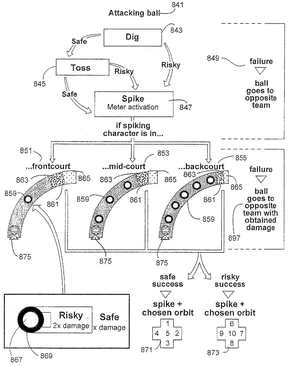
FIG. 15shows an exemplary process for a game action on one side of the net, including exemplary spike meters with exemplary sets of characteristics. In this process, an attacking ball841is approaching from the other side of a net.
In order to properly return the attacking ball, the player on whose side the ball is about to land must first dig843the ball. In this illustrative exemplary non-limiting implementation, the player has the option to perform a dig843using a safe button or a risky button. If the safe button is successfully used, the process proceeds to a toss or “set”845action. If a risky button is successfully used, the process proceeds directly to a spike847action, bypassing the toss845.
If at any point during the setup for the spike meter (i.e. before the actual set that causes the spike meter to be displayed) the player fails to correctly time a button press, the ball goes over to the other team in this implementation.
If the player elected and successfully completed a safe dig843, then the process proceeds to a toss845action. This is the same as a set in actual volleyball. From the toss845action, the player again can chose a risky or safe toss in this exemplary implementation. Both lead to a spike847action upon successful triggering, but, depending on the game, a successful risky action might provide additional power-ups, make a return more difficult, etc.
Again, timing failure results in the ball being returned to the other team.
Once a game character has directed the ball towards a spiking game character, through a risky dig or a toss in this exemplary implementation, the software process performs a meter activation847. Various spike meters may be displayed, shown here are three examples851,853,855of meters dependant on player positioning.
According to this exemplary implementation, if a spiking character is in the front court, a meter851is displayed having few pips859and a wide spike touch861. Within the spike touch861, the various areas for risky865and safe863spikes are large as well.
If the spiking character is at mid-court, however, the spike meter853has additional pips859and a smaller spike touch861. Further, the safe area863of the spike touch and the risky area865of the spike touch have decreased in size.
In the third spike meter855, provided in this exemplary implementation, when a spiking character is in the backcourt, the spike meter has even more pips859and an even smaller spike touch861. On this spike touch, the safe area863has gotten smaller and the risky area865has all but disappeared.
There are many ways for a spike meter to be presented, these three examples are used for illustrative purposes only to show one exemplary manner in which game software may display a spike meter based on a player positioning.
According to this exemplary implementation, in any of the spike instances, if the player miscues on the spike (i.e. on the button press timing in the spike touch), the ball is sent over to the other team with the power it has thus far accrued.
If the player is successful in timing the spike, however, then according to this exemplary implementation the player can additionally select a preferred ball orbit or path based on a directional-pad input. Directional pads871,873are shown for a safe and risky operation respectively. For example, if a player succeeded with a risky spike, that player might push8or down on the directional-pad873instructing a ball that drops very fast. Or, if a player succeeded with a safe spike, the player might push1or up on the d-pad871causing the ball to, for example, loop while in the air. A variety of orbital paths can be imagined, and such a path selection is not necessary if it is not appropriate for a particular game or situation.
In this exemplary implementation, the player has an additional chance to make a risky or safe operation when it comes to each button press timing over each pip. Pips, according to this exemplary implementation, have a larger safe zone869and a smaller risky zone867. As the ball icon875passes over the pip859, the player has a longer opportunity to press a safe button while the ball is in the safe zone869and a briefer opportunity to press the button while the ball is in a risky zone867.
This can add another level of risk/reward to the game. For example, in one exemplary implementation, the determination of whether a button press was successful is based on where the center of the volleyball875is at the time of the button press. If the player presses the safe button, as long as the volleyball875center is anywhere within the larger, safe zone869, the safe push will register. In this exemplary embodiment, the safe zone869corresponds to the area within the entire circle, not just the darkened area. This risky zone867, is a smaller circle within the safe zone.
While a safe button press can be successfully registered while the ball is in the safe zone869or the risky zone267(since the risky zone overlaps the center of the large safe zone269), the risky button press can be successfully registered while the ball is in the risky zone867. This means that a player electing to perform a risky operation may need to more accurately time the press of a risky button. In this exemplary implementation, the player's accuracy is rewarded by a double damage multiplier, although any suitable affect could result from a risky button press success. More than two zones could also be provided within each pip to add additional levels of risk/reward.
Additional software flows can be used, depending on the game being played and a game situation.FIG. 15simply shows an exemplary process and exemplary spike meters used in one particular game situation.
While the technology herein has been described in connection with exemplary illustrative non-limiting implementations, the invention is not to be limited by the disclosure. The invention is intended to be defined by the claims and to cover all corresponding and equivalent arrangements whether or not specifically disclosed herein.
Claims
- A method of playing a battle video game providing a video game play graphical user interface in accordance with instructions executed by at least one processor, the processor providing images for display and changing the images in response to user input, the method comprising: using the at least one processor, modeling at least one ball;using the at least one processor, and initiated based on input from a first user, generating an animation for display that shows the ball flying along a trajectory;using the at least one processor, displaying at least one action indicator along the trajectory of said ball the action indicator having features;using the at least one processor, accepting further input from the first user and determining timing of the further input relative to when the ball has correspondence with features of the action indicator;and using the at least one processor, based on the further input from the first user, applying a power boost to the ball while it is flying along the trajectory.
- The method of claim 1 further including directing the flying ball toward a game character.
- The method of claim 1 further including determining if the player input timing coincides with the ball passing over the features of the action indicator.
- The method of claim 1 further comprising displaying the path the ball will take.
- The method of claim 1 further comprising: using the at least one processor, selectively altering the ball and redirecting the ball towards a virtual target while the ball is in flight;and using the at least one processor, affecting the virtual target responsive at least in part to the selectively altered ball.
- The method of claim 5 wherein the affecting the further virtual target includes changing a further virtual target associated property.
- The method of claim 6 further comprising affecting a responsiveness property associated with the further virtual target.
- The method of claim 6 wherein the changing a further virtual target associated property includes changing a health property associated with the further virtual target.
- The method of claim 8 further comprising disabling the further virtual target if the changed health property crosses a predetermined threshold.
- The method of claim 9 further comprising determining if a predefined target disabling goal has been met.
- The method of claim 1 further including selectively changing the ball's virtual composition while the ball is flying along the trajectory.
- The method of claim 1 wherein applying the power boost increases the ball's virtual damage causing capability when the ball strikes a target.
- The method of claim 1 further comprising displaying the trajectory as a path.
- The method of claim 1 further including providing the action indicator with a plurality of detection zones along the trajectory;and determining whether user input is provided while the ball is within a first of the plurality of detection zones, and determining whether user input is provided while the ball is within a second of the plurality of detection zones smaller than the first detection zone.
- The method of claim 14 wherein the first detection zone encompasses the second detection zone.
- The method of claim 14 wherein the plurality of detection zones comprises a plurality of concentric circles centered at an action indicator center.
- The method of claim 1 wherein the processor applies higher power boost to the ball when the player controls the ball to fly over a shorter path to the target, the shorter path requiring a more precise correspondence between when the player provides input and correspondence between ball position and the action indicator.
- A non-transitory storage device that stores a computer program, for use in simulating a competitive video game, having a processing system, the processing system executing the program to perform the steps of: initiated by user input, directing a displayed ball, having at least one associated characteristic, to fly along a trajectory towards a displayed virtual target;displaying, along the trajectory, at least one action indicator;determining timing of input of a first player;determining a timing relationship between the at least one determined player input timing and coincidence between the displayed virtual ball and the displayed at least one action indicator;and in response to further input by the first player, selectively applying a power boost to the virtual all at least in part responsive to the determined timing relationship while the virtual ball is in flight.
- An apparatus operable to provide a competitive sports video game comprising: a projectile display routine for displaying a virtual ball object on a display and showing the virtual ball object flying through space along a flight path, including initiating flight of the virtual ball object through space along the flight path based on input by a player;a projectile control routine for controlling at least virtual ball object movement along the flight path towards a virtual target;an action indicator display routine for displaying at least one action indicator along the flight path of the virtual ball object;an input timing routine for determining timing of further input of the player a relationship determination routine for determining a relationship between when the virtual ball object coincides in position with at least one displayed action indicator and at least one determined player input timing;and a projectile alteration routine for selectively applying a power boost to the virtual ball object based at least in part on the determined relationship and said at least one determined player input timing.
Disclaimer: Data collected from the USPTO and may be malformed, incomplete, and/or otherwise inaccurate.