U.S. Pat. No. 8,485,895
GAME SERVER, GAME MACHINE UNDER CONTROL OF THE SERVER, AND GAME CONTROL METHOD EXECUTING RETURN ON JUDGMENT THAT CUMULATIVE CREDIT CONSUMPTION REACHES UPPER LIMIT
AssigneeUniversal Entertainment Corporation
Issue DateJuly 31, 2008
Illustrative Figure
Abstract
A game server controls plural game machine groups including a collection of game machines, each of which is brought into a status enabling to start a game based on a thrown coin or a given credit number and is given a payout according to a result of the game. The game server includes a processing unit that judges whether a cumulative credit consumption of a predetermined game machine group reaches a predetermined upper limit, based on information about credit consumptions of the plural game machine groups. The game server also includes a communication interface that sends, when the processing unit judges that the cumulative credit consumption of the predetermined game machine group reaches the predetermined upper limit, a return signal for executing a return based on a predetermined return rate, to one game machine of the predetermined game machine group. The return is executed regardless of a game result.
Description
DETAILS DESCRIPTION OF THE PREFERRED EMBODIMENT One preferred embodiment of the present invention will be described below in detail, based on the accompanying drawings. [Overall Configuration of System] FIG. 1is a diagram showing, in simplified form, the configuration of a credit return system according to one preferred embodiment of the invention. Referring toFIG. 1, this credit return system comprises: (i) a game server1; and (ii) a plurality of game machine groups G01, G02, . . . G10. The game machine groups G01, G02, . . . G10are respectively composed of a plurality of game machines2. These game machine groups are respectively connected via a network NT to the game server1, and can send to and receive from the game server1a variety of information via the network NT. Hereinafter, the whole of these game machine groups G01-01, G01-02, . . . , G01-10is referred to as a “game center.” The game server1collectively controls the game machine groups G01, G02, . . . , G10, and discriminates the source of data sent from these game machine groups G01, g02, . . . , G10, based on the machine-group-numbers being individual to these game machine groups G01, G02, . . . , G10. On the other hand, when the game server1sends data to these game machine groups G01, G02, . . . , G10and the game machines2, the game server1designates the destination of the data by using the corresponding machine-group-number (identification number). Data sent from and received by a game machine2contain: (i) the identification number being individual to this game machine; and (ii) identification information to identify the player currently playing with this game machine. Based on the identification information, the game server1judges whether a game is performed on the game machine2. Hereinafter, the game server is merely referred to as a “server.” ...
DETAILS DESCRIPTION OF THE PREFERRED EMBODIMENT
One preferred embodiment of the present invention will be described below in detail, based on the accompanying drawings.
[Overall Configuration of System]
FIG. 1is a diagram showing, in simplified form, the configuration of a credit return system according to one preferred embodiment of the invention. Referring toFIG. 1, this credit return system comprises: (i) a game server1; and (ii) a plurality of game machine groups G01, G02, . . . G10.
The game machine groups G01, G02, . . . G10are respectively composed of a plurality of game machines2. These game machine groups are respectively connected via a network NT to the game server1, and can send to and receive from the game server1a variety of information via the network NT. Hereinafter, the whole of these game machine groups G01-01, G01-02, . . . , G01-10is referred to as a “game center.”
The game server1collectively controls the game machine groups G01, G02, . . . , G10, and discriminates the source of data sent from these game machine groups G01, g02, . . . , G10, based on the machine-group-numbers being individual to these game machine groups G01, G02, . . . , G10. On the other hand, when the game server1sends data to these game machine groups G01, G02, . . . , G10and the game machines2, the game server1designates the destination of the data by using the corresponding machine-group-number (identification number).
Data sent from and received by a game machine2contain: (i) the identification number being individual to this game machine; and (ii) identification information to identify the player currently playing with this game machine. Based on the identification information, the game server1judges whether a game is performed on the game machine2.
Hereinafter, the game server is merely referred to as a “server.”
[Mechanical Configuration of Game Machines]
FIG. 2is a perspective view showing the appearance of a game machine.FIG. 3is a vertical sectional view of the game machine. Referring toFIGS. 2 and 3, a game machine2is a slot game machine (slot machine) and has a frame body3.
The frame body3is in the shape of hollow box and attached via hinges3A and3B to a front panel4such that it is able to open and shut to the front panel4.
Attached to the rear surface of the front panel4is a casing6, with which three rotating drums5(5A to5C) arranged across the width thereof are covered from their back face.
The drums5A to5C are of tubular shape and are supported rotatively about rotary axes7. Symbol marks (e.g., FIG. “7”, bell, plum, cherry etc.) are respectively drawn on the peripheral surfaces of the drums5A to5C such that the symbol marks are aligned in a row around their periphery. Of the symbol marks drawn on the peripheral surfaces of the drums5A to5C, one symbol mark per drum is visible from the front side of the game machine2via windows8A to8C disposed on the front panel4.
The rotary axes7of the drums5A to5C are attached rotatively via bearings (not shown) to a predetermined bracket (not shown) of the frame of the game machine2. One ends of the rotary axes7are coupled to output axes of stepping motors11A to11C (seeFIG. 4). Therefore, the drums5A to5C are rotatively driven by the stepping motors11A to11C, respectively, and controlled such that they are stopped at a predetermined rotational angle position by a control device12(seeFIG. 4).
Projection parts (not shown) indicating a standard position are disposed on the peripheral end parts of the drums5A to5C. The control device12detects the rotational standard positions of the drums5A to5C when these projection parts cross the optical axes of optical sensors (not shown), which are disposed so as to correspond to the drums5A to5C. The rotational speed of the stepping motors11A to11C is set so as to make constant a speed at which symbol marks are displayed while changing.
Bet line indicator lamps13are disposed adjacent to the windows8A to8C. The lamps13are provided for indicating which line of plural symbol mark stop lines displayed on windows8A to8C has been selected as a bet object.
A control part14is located at the mid section of the front panel4, and a bet button16is disposed in the control part14. The bet button16is provided for setting a bet of medals entered via a throw-in slot15. When the player pushes the bet button16by the amount of medals on which the player desires to bet, the corresponding bet line indicator lamp13is light up. The upper limit of bet medals is three in the game machine2.
The bet lines are different depending on the number of times the bet button16is depressed. By one operation, a single line extending horizontally in the middle stage of the windows8A to8C is the object of bet line. By two operations, the object of bet line amounts to three lines obtained by adding two lines extending horizontally in the upper and lower stage of the windows8A to8C, to the above-mentioned line. By three operations, the object of bet line amounts to five lines obtained by adding two lines on the diagonal of the windows8A to8C, to the above-mentioned three lines. Four or more operations are invalid.
Upon setting a bet medal number according to the above-mentioned procedure, the control device12takes medals corresponding to the bet medal number set by the player. By taking the medals, the condition of starting slot game is established. In this state, when the player operates a start lever17, the control device12rotates the drums5A to5C.
The control part14has three stop buttons18A to18C disposed at locations that correspond to the drums5A to5C, respectively. Upon depressing the stop buttons18A to18C, the corresponding drum is stopped.
The front panel4has digital indicators19for indicating, for example, the number of medals the player threw in for the game; and the number of medals to be discharged.
When one of predetermined specific combinations of symbol marks (winning state) in the drums5A to5C is aligned on the stop line on which the player bets, a medal payout device (not shown) is driven to discharge a predetermined number of medals to a medal payout tray20.
Further, the front panel4has a card inlet22, through which the player inserts a card storing an identification number data to identify the player when he/she plays a game with the game machine2. A card reader23(seeFIG. 4) reads the data of the inserted card.
[Electrical Control Configuration of Game Machine]
FIG. 4is a block diagram showing the electrical configuration of the game machine. Referring toFIG. 4, the control device12of the game machine2comprises: (i) first interface circuit group31; (ii) input/output bus32; (iii) CPU33; (iv) ROM36; (v) RAM37; (vi) random number generator38; (vii) second interface circuit group39; and (viii) communication interface circuit41.
The bet button16is connected to the first interface circuit group31being connected to the input/output bus32. When the player depresses the bet button16, an operation signal is issued from the bet button16to the interface circuit group31. The interface circuit group31converts the operation signal to a predetermined voltage signal and provides it to the input/output bus32. Therefore, before starting a game, a predetermined number of medals corresponding to a value indicated by the operation signal are thrown into the game machine2as the object of bet.
The input/output bus32performs input/output of data signals or address signals to the CPU33.
The start lever17and stop buttons18A to18C arc connected to the first interface circuit group31, on which (i) a start-up signal issued from the start lever17; and (ii) a stop signal issued from the stop buttons18A to18C, are converted to predetermined voltage signals and then provided to the input/output bus32.
When the start lever17is operated to start a game, the start-up signal is provided to the CPU33. Upon receiving the start-up signal, the CPU33issues a control signal to the stepping motors11A to11C in order to rotate the drums5A to5C.
When the stop buttons18A to18C are depressed to stop the drums5A to5C, the respective stop signals from the stop buttons18A to18C are provided to the CPU33. If desired to stop the first drum5A, the player operates the stop button18A. If desired to stop the second drum5B, the player operates the stop button18B. If desired to stop the third drum5C, the player operates the stop button18C. Upon receiving the stop signal, the CPU33issues the stop signal to the stepping motors11A to11C, in order to stop the drum corresponding to the operated stop button.
Rotational position sensors34A to34C are connected to the first interface circuit group31. The sensors34A to34C are disposed in the vicinity of the stepping motors11A to11C, respectively. The sensors34A to34C issue angle position signals that respectively indicate the rotational angle positions of the stepping motors11A to11C, to the interface circuit group31. For example, rotary encoders are usable as the rotational position sensors34A to34C.
Standard position sensors35A to35C are connected to the first interface circuit group31. The sensors35A to35C are disposed in the vicinity of the drums5A to5C, respectively. The sensors35A to35C are optical sensors as described above, and issue standard position signals to the interface circuit group31when detecting the standard positions of the drums5A to5C.
The card reader23, which is disposed within the game machine2, is connected to the first interface circuit group31. The card reader23issues a card status signal at a predetermined timing, in accordance with a signal sending demand from the CPU33. When a card is inserted into the card inlet22, for example, the signal level of the card status signal is higher than a standard level. Based on the change in signal level, the CPU33detects that the card is inserted. On the other hand, when no card is inserted (i.e., the state that the card has been drawn out from the card inlet22), for example, the level of the card status signal returns to the standard level. Based on the change in signal level, the CPU33detects that no card is inserted.
The CPU33detects: (i) an angle position signal issued from the rotational position sensors34A to34C; and (ii) a standard position signal issued from the standard position sensors35A to35C. thereby obtaining data of symbol marks displayed on the windows8A to8C.
The ROM36and RAM37are connected to the input/output bus32. The ROM36stores: (i) a program for controlling the game machine and returning medals; and (ii) an initial value of variable used in the program. Additionally, the ROM36stores data group indicating correspondence between a combination of symbol marks and random numbers. On the other hand, the RAM37stores flags and variable values.
The communication interface circuit41is connected to the input/output bus32. The circuit41is used when performing sending/receiving of data between the game machine2and server1.
The random number generator38for generating the above random numbers is connected to the input/output bus32. When the CPU33issues an instruction for generating random numbers to the random number generator38, the random number generator38generates random numbers in a predetermined range, and issues signals indicating the random numbers to the input/output bus32. When a random number is issued from the random number generator38, in order to determine a combination of symbol marks that corresponds to the random number, the CPU33searches the above data group and then substitutes a value corresponding to the combination for variables.
Usually either normal game or special game can be played with the game machine2.
In the normal game, there are (i) an enabled prize-winning status that a combination of symbol marks stopped and displayed on an effective line can match a prize-winning pattern, and (ii) unabled prize-winning status that a combination of symbol marks cannot match a prize-winning pattern.
In the unabled prize-winning status, examples of symbol mark combinations that are changed on effective lines are: (i) failure pattern; and (ii) small prize pattern. The term “small prize” means that a predetermined number of symbol marks such as “cherry” and “bell” are aligned on one of the effective lines, and a few medals are discharged to the payout tray20. On the other hand, the term “failure pattern” means that symbol marks are not aligned on any effective line, and no medals are discharged. The unabled prize-winning status can move to the enabled prize-wining status by an internal lottery processing. In the unabled prize-winning status, any prize-winning pattern cannot be aligned irrespective of a timing at which the stop buttons18A to18C are depressed. Hence, it is impossible to move from the normal game status to the special play status.
On the other hand, only in the enabled prizewinning status, a combination of symbol marks stopped and displayed by a timing at which the stop buttons18A to18C are depressed will match a prize-winning pattern. In other words, this state allows for “aiming (observation push).” When a combination of symbol marks stopped and displayed on an effective line matches a prize-winning pattern, the player wins a prize and the game style moves to the special game providing a chance of obtaining a large number of medals. On the other hand, when the player fails to obtain any prize-winning pattern by missing a timing of depressing the stop buttons18A to18C, the above-mentioned failure pattern or small prize pattern is aligned on the effective line. If once the enable prize-winning status is set, this status continues until a combination of symbol marks stopped and displayed matches a prize-winning pattern. There is no moving to the unable prize-winning status.
In the special game, there is extremely high probability that a combination of symbol marks stopped and displayed on an effective line will match a small prize pattern. This leads to a high possibility of obtaining a large number of medals. Upon finishing the special game, the game style moves to the normal game. When the normal game is performed after the special game, whether the game proceeds in the enabled prize-winning status or the unabled prize-winning status is to be determined by an internal lottery processing.
The second interface circuit group39is also connected to the input/output bus32. To the circuit group39, there are connected: (I stepping motors11A to11C; (ii) bet line indicator lamp13; (iii) score indicator19; and (iv) speaker40. The circuit group39supplies a drive signal or drive power to each of these devices, For instance, when the player depresses the bet button16, a drive current is applied to the bet line indicator lamp13, in order to indicate a bet line that becomes effective in accordance with the number of throw-in medals. When the game is over, a drive signal is applied to the score indicator19, in order to indicate the score corresponding to the prize-winning status. The speaker40makes an effective sound-corresponding to the game status when the game is started or over.
[Configuration of Game Server]
FIG. 5is a block diagram showing the electrical configuration of the game server. Referring toFIG. 5, a server1has a data bus BUS. To the data bus BUS, there are connected (i) CPU51; (ii) memory52; (iii) communication interface53; and (iv) database54.
The CPU51executes various processing according to programs stored in the memory52. Concretely, the CPU51receives data from the game machine2via a communication line connected by the communication interface53, and stores the data in the memory52. This data contains for example the upper limit data and return rate data of a plurality of game machines2under the control of the server1, that is, information sent from the individual game machines2under the control of the server1. The CPU51reads a program stored in the database54on the memory52, and progresses the program based on the information sent from each game machine2that is stored in the memory52. The progress of the program is stored in the database54.
It is assumed in the following, for purposes of description, that the game machine2is activated in advance, and flags and variables are initialized to a predetermined value.
[Operation of Game Machine]
FIG. 6is a flowchart showing the flow of control of game machines. Referring toFIG. 6, firstly, the CPU33with the game machines2judges whether the bet button16is depressed by the player (step S11). The bet-button operating judgment processing is executed in accordance with the operation of depressing the bet button16, and includes the following processing: (i) detecting whether an operation signal is issued from the bet button16in response to an operation to the bet button16, thereby storing the number of throw-in medals with the operation; and (ii) issuing a drive signal to the bet line indicator lamp13, in order to indicate the bet line that becomes effective in accordance with the number of throw-in medals.
Upon completing the above-mentioned bet-button operating judgment processing, the CPU33judges whether the pressing operation of the bet button16is performed and the operation of the start lever17is performed (step S12). When the CPU33judges both operations are performed, the CPU33moves the processing to step S13. On the other hand, when the CPU33judges both are not performed or none of these operations are performed, the CPU33returns the processing to step S11, and performs the bet-button operation processing again. A period of time that all the drums5A to5C arc started in rotation and are brought into a stop is a sequence of game (play).
Moving to the processing of step S13, the CPU33executes an internal lottery processing. The internal lottery processing includes processing of: (i) controlling the random number generator38to generate a random number, and (ii) searching data group indicating the correspondence between combinations of symbol marks and random numbers, thereby deciding a combination of symbol marks in accordance with the generated random number. The combination of symbol marks stopped and displayed on the previous game is stored in the RAM37. In the following game, the CPU33reads the combination of symbol marks stored in the RAM37, so that it is used for internal lottery processing.
In the internal lottery processing, a combination of symbol marks that can be stopped and displayed is determined by lottery, and a value indicating the lottery result is substituted for a lottery data of the currently performing game (current game lottery data). For instance, when it is in the unabled prize-winning status and in failure pattern, the current game lottery data is set to “00”. When it is in the unabled prize-winning status and there occurs the symbol marks combination matching with a small prize pattern, the current game lottery data is set to “01”. When it is in the enabled prize-winning status, the current game lottery data is set to “12”. When it is in the special play status and in failure pattern, the current game lottery data is set to “20”. When it is in the special play status and there occurs the symbol marks combination matching with a small prize pattern, the current game lottery data is set to “21”. In an alternative, it may be checked whether the player has moved to an advantageous state based on the stopped symbol marks, without performing any internal lottery processing.
Upon completing the above-mentioned processing of step S13, the CPU33reads a subroutine about stepping motor control processing (not shown) and based on this subroutine, issues control signals to the stepping motors11A to11C, in order to drive each motor at a predetermined rotational speed (step S14). The term “rotational speed” means a speed at which the symbol marks are changeably displayed by the rotation of the drums5A to5C in the above-mentioned sequence of game (play), and means that any speed in the transient rotation state, such as of immediately after the drums5A to5C starts rotation and immediately before they are brought into a stop, are excluded from the concept of the rotational speed.
There is a lottery data of the game performed in the past that corresponds to the above-mentioned current game lottery data. The past game lottery data is data indicating the lottery result of the game performed before the current game, and the data is stored in the RAM37. In the normal game to which the game style moves when the special game is over, the past game lottery data is reset at the time of performing the first game. The past game lottery data is updated by sequentially accumulating the current game result in the previous game result.
Upon completing the above-mentioned stepping motor control processing, the CPU33judges whether the player depressed any one of the stop buttons18A to18C in order to stop the drums5A to5C, and from which stop button a stop signal is issued (step S15). When the judgment result is that no stop signal is issued from the stop buttons18A to18C, the CPU33executes again the processing of step S15. On the other hand, when the judgment result is that a stop signal is issued from any one of the stop buttons18A to18C, the CPU33performs processing for stopping the stepping motors11A to11C (step S16). This stepping motor stop control processing includes: (i) controlling the random number generator38to generate a random number; and (ii) searching data group indicating the correspondence between combinations of symbol marks and random numbers, thereby deciding a combination of symbol marks in accordance with the generated random number.
The CPU33obtains symbol marks currently appearing on the windows8A to8C, based on (i) a rotational position signal issued from the rotational position sensors34A to34C; and (ii) a standard position signal issued from the standard position sensors35A to35C. The CPU33controls the stepping motors11A to11C and decides a stop position, based on (i) the above-mentioned symbol mark data, and (ii) the current game lottery data set in the above-mentioned internal lottery processing (step S13).
Although the CPU33stops the stepping motors11A to11C in accordance with the current game lottery data, if decided that any one of the stop buttons18A to18C is depressed, the CPU33can apply an additional drive to the stepping motors11A to11C, under prescribed conditions. Concretely, when any symbol mark corresponding to the current game lottery data cannot be stopped and displayed, the stepping motors11A to11C are subject to an additional drive in the range of the maximum amount of four symbol marks. In this connection, if any symbol mark corresponding to the current game lottery data is not present in that range, it is impossible to stop and display any symbol mark corresponding to the current game lottery data. For instance, even when in the enabled prize-winning status, two drums are already stopped and there is a symbol mark(s) allowing for match with a winning pattern, whether the player obtains the winning pattern depends on the timing at which the player operates the stop button corresponding to the last drum to be stopped. On the other hand, when in the unabled prize-winning status, two drums are already stopped and there is a symbol mark(s) allowing for a winning pattern, the stepping motors11A to11C are controlled so as not to provide a match with the winning pattern, irrespective of the timing of operation of the stop button corresponding to the last drum to be stopped.
Upon completing the above-mentioned stepping motor stop control processing, the CPU33judges whether all the stop buttons18A to18C are depressed (step S17). In other words, in the judgment processing of step S17, it is judged whether there are detected all the stop signals issued in accordance with the depressing operation to the stop buttons18A to18C. In this connection, when the judgment result is that all of the stop buttons18A to18C are not operated, the CPU33returns the processing to step S15. On the other hand, when the judgment result is that all the stop buttons18A to18C are operated, the CPU33moves the processing to step S18.
Moving to the processing of step S18, the CPU33judges whether a combination of symbol marks aligned on the line that becomes effective matches with a winning status, and pays out game medals corresponding to the winning status. In this medal payout processing, when the judgment result is that (i) the combination of symbol marks aligned in the effective line and (ii) the wining state are each matched, the CPU33calculates the number of payout medals corresponding to the winning status, and pays out the number of medals corresponding to the calculated number. Thereafter, the CPU33moves the processing to step S19. On the other hand, when the judgment result is that the combination of symbol marks aligned in the effective line and the winning state are not matched, the CPU33moves the processing to step S19, without executing any medal payout.
Moving to the processing of step S19, the CPU33mainly stores the current game lottery data (step S19). In this preferred embodiment, the CPU33terminates the processing of storing the current game result when a past game lottery data is read from the RAM37and stored the current game lottery data together with the read past game lottery data in the RAM37. At this time, for example, data indicating the actually stopped and displayed symbol marks in the present game is also stored in addition to the present game lottery data.
[Flow of Operation of Game Machine]
FIG. 7is a flowchart showing the flow of operation of game machines. The procedure shown in this flowchart is performed concurrently with the subroutine of the game machines2shown inFIG. 6.
Referring toFIG. 7, the game machine2detects and identifies or discriminates the player (step S20). This player identification (discrimination) processing is to be performed by the CPU33with the game machine2, in order to judge whether a game is being performed on the game machine2.
The reason why the player discrimination processing is particularly necessary is that a return is executed per game machine group (when the cumulative credit consumption of a game machine group reaches an upper limit, a return is executed to a certain game machine in the game machine group) in this preferred embodiment, unlike the conventional game machine executing a return per game machine. That is, to avoid the case that the return is executed to the game machine where nobody performs a game, it is necessary to check whether a game is performed on the individual game machines. Following is a method of judging whether the game machine is in the play status.
Play status judgment is processing for judging whether there is a player performing a game on a game machine2(i.e., whether the game machine2is in play). When the game machine2is not in play status, the following processing is unnecessary. It is therefore necessary to firstly check whether the game machine2is in play. The play status judgment is performed by detecting whether a card is inserted into the card inlet22provided on the front panel4of the game machine2.
This card detection is achieved by detecting whether a card is inserted into the card inlet22with the card reader23. The card to be inserted is an identification card storing information to identify the player, which can have any function other than identification. For example, a card (e.g., a prepaid card) storing information to identify the player can be used.
When the result of the card detection is that no card is inserted, the CPU33terminates the player discrimination processing. At this time, the CPU33sends the server1a signal of discrimination result that no card is detected. As the contents of signals related to the card detection, for example, data “0” is sent when no card is detected, and data “1” is sent when a card is detected. This way, the server1controls a game machine on which no card is detected, thereby avoiding that the return is executed to the game machine on which no player is present.
The results of judgment whether the game machines2of the game machine groups G01, G02, . . . , G10are in play or not, are stored in the database54with the server1. This storage is updated properly and used in a lottery for selecting a game machine to which a return is executed.
Although in this preferred embodiment, an identification card storing data to verify the player or an ID card is used as means for discriminating the player, the following means are applicable. For example, a human sensor to detect human body may be attached to the game machine2. Alternatively, a stool on which the player sits for performing a game may have the function of weighing such that the player's body weight is weighed and stored in order to identify the player.
Upon completing the above-mentioned sequence of player discrimination processing, the CPU33with the game machine2sets an upper limit value that is a standard for return (step S21). The upper limit value is the number of medals, as a game medium, which is used for performing a game on a slot game machine etc. When in a certain game machine group, the total number of medals used by the game machines of the game machine group reaches the upper limit value, the return is executed to a certain game machine of the game machine group.
For setting such upper limit value, preset upper limit values being individual to the game machine groups (G01, G02, . . . , and G10) are used. These preset upper limit values are stored in the RAM37with the game machines2of the game machines groups (G01, G02, . . . , and G10). The CPU33reads the upper limit value data from the RAM37and then terminates the upper limit value setting.
Upon completing the above-mentioned upper limit value setting processing, based on the judgment processing result in step S11shown inFIG. 6, the CPU33adds the number of medals that the players threw in as a game medium (step S22). The processing for adding the medal throw-in number is to calculate the accumulating total of medals that the players threw in the game machines to perform a game. A medal sensor (not shown) provided within the game machine2counts medals thrown in through the throw-in slot15. The counted number data is added to a cumulative throw-in number data, which is data of medals thrown in the past, and stored as a current throw-in medal data. Hereinafter, the cumulative consumption of credit is referred to as a “cumulative throw-in number of medals.”
The above-mentioned cumulative throw-in number data is stored in the RAM37. The CPU33executes the following processes of: (i) reading data of the past throw-in medal from RAM37; (ii) adding data of the current throw-in medal counted by the medal sensor to data of the cumulative throw-in number; and (iii) storing the result of addition as updated cumulative throw-in number data in the RAM37. At a predetermined timing, this cumulative throw-in number data is sent from each game machine2to the server1via the communication interface circuit41, network NT, and communication interface53with the server1. The cumulative consumption data sent from the individual game machines2are controlled by the corresponding game machine groups (G01, G02, . . . , and G10), and used for judging whether the cumulative credit consumption of the game machine groups (G01, G02, . . . , and G10) reaches a predetermined upper limit.
Upon completing the above-mentioned throw-in medal number addition processing, the CPU33judges whether the cumulative throw-in number reaches the upper limit (step S23). The game machines2receive the result of judgment made by the server1. The server1judges by comparing (i) the cumulative throw-in number data sent from the individual game machines2at a predetermined timing in the processing of step S22; and (ii) the upper limit value set in the processing of step S21(this value is also stored in the database54with the server1). The judgment result obtained by the server1is sent to all the game machines2of the corresponding game machine groups G01, G02, . . . , G10. The server1sends the game machines2via the communication interface53, network NT, and communication interface circuit41, a numerical data of “1” when it reaches the upper limit, and a numerical data of “0” when it does not reach the upper limit.
When the judgment result is that the cumulative throw-in number data does not reach the upper limit, the CPU33returns the processing to step S22, and continues processing for adding the number of medals that the players throw in the game machines2.
On the other hand, when the judgment result is that the cumulative throw-in number reaches the upper limit, the CPU33sends a play status to the server1(step S24). In the processing for sending the play status to the server1, a game machine2, which has received from the server1a signal indicating that the cumulative throw-in number data reached the upper limit in the above-mentioned processing of step S23, sends the server1a signal indicating that a game is being performed on the game machine2.
By this processing for sending a signal indicating the play status, the server1can confirm which game machines2are in play among the game machine group G01, G02, . . . , or G10, to which the server1executes the return. For example, if an identification number of “123” is assigned to the game machine2that has received a signal indicating the arrival at the upper limit, among the plurality of game machines under control of the server1, a signal of “123-1” (here the numerical value of “1” that is a signal indicating the play status is hyphenated with the identification number of “123” of the game machine2) is sent to the sever1.
Upon completing the above-mentioned processing for sending a signal indicating the play status to the server1, the CPU33waits for a return instruction (step S25). The return instruction is a signal to be sent from the server1to a game machine2that the server1has selected as a return destination from the game machines2contained in the game machine group (G01, G02, . . . or G10), the cumulative throw-in number data of which reaches the upper limit. The game machine2allows the player to perform a game even when waiting for the return instruction.
A signal indicating the execution of a return is sent from the server1to the game machine2as the return destination, via the communication interface53with the server1, network NT, and communication interface circuit41with the game machine2. Concretely, this signal is obtained by affixing the numerical value of “1” indicating the execution of the return, to the machine-number as the return destination.
In the above-mentioned return instruction waiting status, the CPU33judges whether notification should be executed or not (step S26). The notification is to notify that the return will be executed from now to the game machine2installed in the game center. The notification judgment processing is to judge whether notification should be executed before or after the return is executed.
By referring to the data stored in the RAM37, the CPU33determines when notification should be executed (step S27). The RAM37stores data about the timing of notification. Data of “1” is assigned when performing notification before the return is executed. On the other hand, data of “0” is assigned when performing notification after the return is executed. These data may be preset to the game machine2. Alternatively, the server1may determine by lottery every time and send the content thus determined to the game machine2.
When the data stored in the RAM37is “1”, the CPU33notifies the player the content that the return will be executed to the game machine2on which the player is performing a game (step S28). This notification may be executed by using an illuminator provided within the game machine2. Alternatively, the game machines2may have a display part performing notification to the player. Further, any notification means for letting the player know if his game machine receives the return may be employed, whether it be provided integrally with the game machines2.
When the above-mentioned notification processing is completed, or when it is set that notification is performed after the return is executed, the CPU33judges whether the return instruction is received (step S29). This return instruction is one that the game machine2waits for its arrival from the server1in the processing of step S25. At a predetermined timing, the server1sends a signal that is the return instruction to the game machine2via the communication interface53. In the game machine2, the CPU33receives the return instruction via the communication interface circuit41and input/output bus32. If the return instruction is not received, the CPU33returns the processing to step S25, and waits for the return instruction again.
As the above-mentioned signal that the server1sends, the numerical data of “1” is sent to the game machine that has been selected by lottery, as the return destination. On the other hand, the numerical data of “0” is sent to other game machines that have not been selected as the return destination.
Upon completing the above-mentioned return instruction receiving processing, the CPU33executes return processing (step S30). This return processing is executed based on the return instruction issued from the server1in the above-mentioned processing of step S29. When the signal content is the numerical data of “1” that indicates the execution of a return, the CPU33receives from the server1data indicating to what extent the return should be executed to the game machine2, and executes the return based on this data. The number of medals to be returned can be calculated by multiplying (i) the upper limit value of the corresponding game machine group G01, G02, . . . , or G10, which is stored in the RAM37, by (ii) a predetermined return rate. On the other hand, when the signal content is the numerical data of “0” that indicates no return execution, the CPU33terminates the processing without executing any return in step S30.
Upon completing the above-mentioned return processing, the CPU33moves again the processing to the upper-limit value setting processing (step S21), and repeats the above-mentioned sequence of processes.
[Operation of Game Server]
FIG. 8is a flowchart showing the flow of operation when the game server1makes preparation for return. This operation is always repeated in the server1.
The server1always holds some of medals that have been thrown as a game medium in the individual game machines2in the game machine groups (G01, G02, . . . , and G10) under control of the server1, in preparation for the execution of a return when the game machine group (G01, G02, . . . , or G10) reaches the upper limit.
Referring toFIG. 8, the server1waits for the game medium throw-in result from the game machine groups (G01, G02, . . . , and G10) (step S41). As the game medium that the player uses on each game machine2, it is possible to use any tangible matters, e.g., medals, winning balls, or coins, each being used generally. Besides these, any intangible matters that can be expressed in numerical value as data are also handled as a game medium in this preferred embodiment. The term “throw-in” means the following action that a player makes a game machine recognize the game medium for the purpose of playing a game, irrespective of the type of the game medium. Therefore, not only a medal etc. that is thrown in through the throw-in slot15and detected by the medal sensor of the game machine2, but also numerical value data etc. that the player decides to use for the game may be a subject matter that the server1wait for.
The data of the number of game media thrown in the game machine2are, as described above, sent from the individual game machines2to the server1. The server1controls the received data in units of the game machine groups (G01, G02, . . . , and G10).
In the status that the server1is waiting for throw-in of a game medium, the CPU51with the server1judges whether game medium throw-in data have been received at a predetermined timing (step S42). In this preferred embodiment, medals are used as the game medium, and the player continues a game on the game machine2, while throwing in medals via the throw-in slot15. The number of these medals is detected by the medal sensor with the game machine2, and made into a numerical value as data. This numerical value data is stored as cumulative throw-in number data in the RAM37with the game machine2. At a predetermined timing, this cumulative throw-in number data is sent to the server1via the communication interface circuit41. On the other hand, the server1receives this cumulative throw-in number data via the communication interface53. Based on an instruction of the CPU51, the received cumulative throw-in number data are properly stored (held) in the memory52, in units of the game machine groups G01, G02, . . . , G10. When the judgment result of step42is that the server1has received no throw-in data, the CPU51returns the processing to step S41.
Upon completing the throw-in data receiving judgment processing, the CPU51holds a predetermined rate of the throw-in number (step S43). As stated above, the server1is constructed so as to hold in advance the game medium for the return to the player performing a game on the individual game machine2under control of the server1. The game machine groups (G01, G02, . . . , and G10) have different hold amounts. The hold amount is determined by multiplying the cumulative throw-in number data of the corresponding game machine group (G01, G02, . . . , or G10), which the server1received in step S42, by a predetermined rate (return rate).
In this hold processing, the server1sends via the communication interface53a numerical value data corresponding to the hold amount calculated by the CPU51to the game machines2contained in the corresponding game machine group (G01, G02, . . . , or G10).
Upon completing the above-mentioned hold processing, the CPU51with the server1returns to the state of waiting for throw-in data from the game machine groups (G01, G02, . . . , and G10) (step S41), and repeats the foregoing sequence of processes.
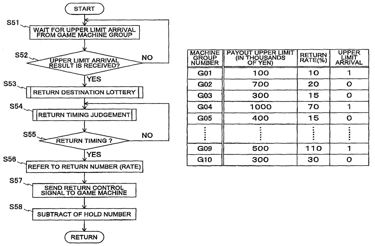
FIG. 9is a flowchart showing the flow of operation when the game server executes the return. This operation is always repeated.
Referring toFIG. 9, firstly, the CPU51with the server1waits for an upper limit arrival result from the game machine groups (G01, G02, . . . , and G10) (step S51). This upper limit arrival result indicates that the total game media thrown in each game machine2of the corresponding game machine group (G01, G02, . . . , or G10), reaches a preset amount, as described above. Judgment whether it reaches the upper limit is made on the server1. When the judgment result is the arrival of the upper limit, the result is sent from the server1to the individual game machines2of the corresponding game machine group G01, G02, . . . , or G10. Upon receiving this result, the individual game machines2send a signal indicating recognition of the upper limit arrival. The server1waits for this upper limit arrival signal via the communication interface53.
When the server1is waiting for the upper limit arrival result, at a predetermined timing, the server1judges whether the upper limit arrival result has been received (step S52). The CPU51executes this judgment. When the judgment result is that the upper limit arrival result has been received, the CPU51moves the processing to the step S53. On the other hand, the judgment result is that any upper limit arrival result has not been received, the CPU51returns to the upper limit arrival result wait processing (step S51), and repeats judgment whether the upper limit arrival result has been received, at the predetermined timing.
Moving to the processing of step S53, the CPU51selects a return destination by lottery. As an example of the lottery for selecting a return destination, there is such a style that “a return will be executed to a game machine of which machine-number meets a lottery number, among the game machines that form the corresponding game machine group and are in play.” By referring to the machine-numbers of the game machines2that have sent the signal indicating the recognition of the upper limit arrival, the CPU51performs a lottery for selecting one from these machine-numbers. This lottery result is then stored in the memory52, based on an instruction of the CPU51.
Upon completing the above-mentioned return-destination lottery processing, the CPU51judges a return timing (step S54). The return timing can be set variously. For example, to the game machine that has reached the upper limit and been selected as the return destination, the return is forced to execute immediately after all the processes on the server1are terminated. Alternatively, the return is executed after an elapse of a predetermined period of time from the termination of all the processes on the server1, or after performing a predetermined number of games.
This processing for judging a return timing is to judge at which timing the return should be executed. If the return timing is predetermined uniquely, the return timing is employed.
Upon completing the above-mentioned return timing judgment processing, the CPU51judges whether the return timing is established (step S55). The term “return timing” is one that has been determined in the processing of step S54, and this return timing is stored in the memory52with the server1. For instance, if given a temporal timing such as “after a predetermined number of minutes from the upper limit arrival,” a timer (not shown) within the server1is used to control this timing. If given a timing based on the player's game circumstances such as “when the player performs twenty games after the upper limit arrival,” various sensors within the game machine2are used to judge whether predetermined conditions are satisfied. At the time the conditions are satisfied, a signal indicating this content is sent from the CPU33with the game machine2to the server1.
When the judgment result is that no return timing is established, the CPU51returns the processing to step S54, and repeats the processing from step S54.
On the other hand, when the judgment result is that the return timing is established, the CPU51refers to a return number (step S56). When the cumulative credit consumption of the game machine group (G01, G02, . . . , or G10) reaches a predetermined upper limit, a return is executed based on the result obtained by multiplying the upper limit value by a preset return rate on the server1side. At this time, the CPU51refers to a game table, indicating the relationship between return rates and data of the upper limits of game machine groups as a return destination.
FIG. 10shows an example of the game table stored in the database54with the server1. Referring toFIG. 10, the contents registered on this table are (i) the group-number of a plurality of game machine groups (G01, G02, . . . , and G10: game-machine-group-numbers) installed in a game center under control of the server1; (ii) the payout upper limits and return rates being individual to the game machine groups (G01, G02, . . . , and G10); and (iii) data indicating whether they reach a predetermined upper limit. The CPU51refers to the value “return rate” on this game table in order to calculate the credit number to be used for executing a return.
Referring again toFIG. 9, upon completing the above-mentioned return number reference processing, the CPU51sends a return control signal to the game machine2as a return destination (step S57).
The return control signal, which is sent from the server1to each game machine2included in any of the game machine groups: G01, G02, . . . , and G10where the server1executes the return, gives the value of “1”, which indicates that the game machine2is the return destination, to some game machine2being determined as the return destination in step S51. While it gives the value of “0”, which indicates that the game machine2is not the return destination, to other game machine2being determined as the not return destination in step S51.
This return control signal contains data indicating the degree (amount) of the return. The data contained in the return control signal are sent via the communication interface53, based on an instruction of the CPU51.
Upon completing the above-mentioned processing for sending the return control signal, the CPU51subtracts a hold number (step S58). The term “hold number” means the game medium number that was held in the memory52with the server1in the processing of step S43shown inFIG. 8. This hold game medium is used for the return to each game machine2. It is therefore necessary to perform subtract processing of the game medium number data corresponding to the return amount.
By this hold number subtraction processing, the hold number data is updated and stored in the memory52.
In the case of changing the return amount to a game machine2depending on the play status, there may be configured such that when the return to the game machine2is completed, the CPU33with the game machine2sends the server1data indicating the return amount to the player and subtraction processing is started after receiving this data.
Upon completing the above-mentioned hold number subtraction processing, the CPU51returns the processing to step S51, and resumes the processing for waiting for upper-limit arrival result and later processing.
[Operations and Effects]
This preferred embodiment produces mainly the following operations and effects.
In a game center installing a plurality of game machine groups as a collection of game machines, a game server collectively controls the cumulative credit consumption of the individual game machine groups. At this time, when the cumulative credit consumption of a certain game machine group reaches a predetermined upper limit, a return is executed to a certain game machine of this game machine group. As a result, unevenness of the probability of a prize, which has been the problem of the conventional game machines, can be solved in the form of “return.” Further, it is possible to provide a game machine of higher game characteristics by the presence of such gambling characteristics that it remains to be seen which game machine will receive a return. It is also possible to solve the problem of extremely low probability of release, as in the conventional jackpot, by controlling the return per game machine group. The effect of these is that the entire game center becomes lively and the problem of customer missing can be eliminated.
While but one embodiment of the invention has been shown and described, it will be understood that many changes and modifications may be made therein without departing from the spirit or scope of the present invention.
Claims
- A game server for collectively controlling a plurality of game machine groups installed in a game center, said plurality of game machine groups including a first game machine group and a second game machine group respectively including a plurality of game machines, each of which is brought into a status enabling to start a game based on a thrown coin or a given credit number and is given a payout according to a result of said game, said game server including: a memory configured to individually store cumulative credit consumptions of each of said plurality of game machine groups, wherein said memory has a plurality of units for each of said game machine groups respectively storing a cumulative credit consumption of each of said game machine groups;judge means for judging whether a cumulative credit consumption of a predetermined game machine group reaches a predetermined upper limit, based on information stored in said memory, and for executing a return at a time point depending on a game condition of one game machine of said predetermined game machine group, after a completion of a lottery to select the one game machine where the return is to be executed;and first sending means for sending, when said judge means judges that said cumulative credit consumption of said predetermined game machine group reaches the predetermined upper limit, a return signal for executing said return based on a predetermined return rate, to the one game machine of said predetermined game machine group, said return being executed regardless of a game result, wherein at least one of the predetermined upper limit and the predetermined return rate is individually set for each of said plurality of game machine groups and wherein the game machines in the first game machine group are different from the game machines in the second game machine group.
- The game server according to claim I, further including: lottery means for determining by the lottery the game machine to which said return is executed.
- The game server according to claim 2 , further including: second sending means for sending a notification signal to notify the one game machine of said predetermined game machine group that said return will be executed or that said return was executed.
- The game server according to claim 1 , further including: second sending means for sending a notification signal to notify the one game machine of said predetermined game machine group that said return will be executed or that said return was executed.
- The game server according to claim 1 , wherein the return is executed to the one game machine, which has been selected by the lottery in said predetermined game machine group, after confirming that the one game machine is in play.
- A game machine that is controlled by a game server for collectively controlling a plurality of game machine groups including a first game machine group and a second game machine group and installed in a game center, the game machine included in a game machine group of said plurality of game machine groups, said game server judging whether cumulative credit consumptions of said game machine groups reach predetermined upper limits, based on information stored in a memory configured to individually store cumulative credit consumptions of each of said plurality of game machine groups, wherein said memory has a plurality of units for each of said game machine groups respectively storing a cumulative credit consumption of each of said game machine groups, the game machine brought into a status enabling to start a game based on a thrown coin or a given credit number and is given a payout according to a result of said game, said game machine including: a first receiving means for receiving a return signal sent from said game server, said first receiving means receiving the return signal, when said game server judges that said cumulative credit consumption of said game machine group reaches the predetermined upper limit, the return signal executing a return based on a predetermined return rate, said return being executed regardless of a game result, and when said game server executes a return at a time point depending on a game condition of the game machine, after a completion of a lottery to select the game machine where said return is to be executed and a display configured to display symbol combinations as a result of said game, wherein at least one of the predetermined upper limit and the predetermined return rate is individually set for each of said plurality of game machine groups and wherein game machines in the first game machine group are different from game machines in the second game machine group.
- The game machine according to claim 6 , further including: return means for executing said return based on a result of the lottery performed by said game server.
- The game machine according to claim 7 , further including: second receiving means for receiving a notification signal sent from said game server.
- The game machine according to claim 6 , further including: second receiving means for receiving a notification signal sent from said game server.
- The game machine according to claim 6 , wherein the return is executed to the game machine, which has been selected by the lottery in said game machine group, after confirming that the game machine is in play.
- A method for collectively controlling a plurality of game machine groups installed in a game center, said plurality of game machine groups including a first game machine group and a second game machine group respectively including a plurality of game machines each of which is brought into a status enabling to start a game based on a thrown coin or a given credit number and is given a payout according to a result of said game, and said game center comprising a memory configured to individually store cumulative credit consumptions of each of said plurality of game machine groups, wherein said memory has a plurality of units for each of said game machine groups respectively storing a cumulative credit consumption of each of said game machine groups, said method including: judging whether a cumulative credit consumption of a predetermined game machine group reaches a predetermined upper limit, based on information stored in said memory;executing a return at a time point depending on a game condition of one game machine of said predetermined game machine group, after a completion of a lottery to select the one game machine where said return is to be executed and sending, when a result of said judging is that said cumulative credit consumption of said predetermined game machine group reaches the predetermined upper limit, a return signal for executing said return based on a predetermined return rate, to the one game machine of said predetermined game machine group, said return being executed regardless of a game result, wherein at least one of the predetermined upper limit and the predetermined return rate is individually set for each of said plurality of game machine groups and wherein the game machines in the first game machine group are different from the game machines in the second game machine group.
- The method according to claim 11 , further including: determining by the lottery the game machine to which said return is executed.
- The method according to claim 12 , further including: sending a notification signal to notify the determined game machine of said predetermined game machine group that said return will be executed or that said return was executed.
- The method according to claim 11 , further including: sending a notification signal to notify the determined game machine of said predetermined game machine group that said return will be executed or that said return was executed.
- The method according to claim 11 , wherein the return is executed to the one game machine, which has been selected by the lottery in said predetermined game machine group, after confirming that the one game machine is in play.
- A game server for collectively controlling a plurality of game machine groups installed in a game center, said plurality of game machine groups including a first game machine group and a second game machine group respectively including a plurality of game machines, each of which is brought into a status enabling to start a game based on a thrown coin or a given credit number and is given a payout according to a result of said game, said game server including: a memory configured to individually store cumulative credit consumptions of each of said plurality of game machine groups, wherein said memory has a plurality of units for each of said game machine groups respectively storing a cumulative credit consumption of each of said game machine groups;a processing unit that judges whether a cumulative credit consumption of a predetermined game machine group reaches a predetermined upper limit, based on information stored in said memory, and that executes a return at a time point depending on a game condition of one game machine of said predetermined game machine group, after a completion of a lottery to select the one game machine where the return is to be executed;and a communication interface that sends, when said processing unit judges that said cumulative credit consumption of said predetermined game machine group reaches the predetermined upper limit, a return signal for executing said return based on a predetermined return rate, to the one game machine of said predetermined game machine group, said return being executed regardless of a game result, wherein at least one of the predetermined upper limit and the predetermined return rate is individually set for each of said plurality of game machine groups and wherein the game machines in the first game machine group are different from the game machines in the second game machine group.
Disclaimer: Data collected from the USPTO and may be malformed, incomplete, and/or otherwise inaccurate.