U.S. Pat. No. 8,480,493
ARCADE-STYLE GAME CONTROLLER FOR A TABLET COMPUTING DEVICE
AssigneeinMusic Brands, Inc.
Issue DateJanuary 10, 2012
Illustrative Figure
Abstract
A game controller for a tablet computing device is disclosed. The controller includes a control console. A groove on a top portion of the control console configured and arranged to capture an edge of a tablet computing device in an upright orientation. A number of controls are included on the control console for transmitting game control inputs to the tablet computing device.
Description
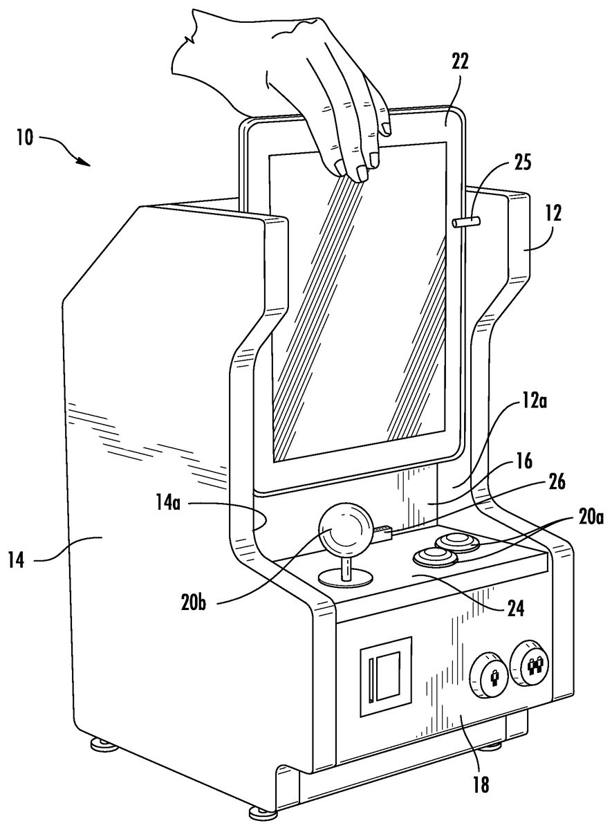
DESCRIPTION OF THE PREFERRED EMBODIMENT Referring now toFIG. 1, a first embodiment of the game controller of the present invention is shown generally at10. The first embodiment of the game controller10of the present invention includes an aesthetic cabinet with arcade-style game controls. The cabinet generally includes a left side12, right side14, rear, top, bottom, and front portion16and is sized and dimensioned to fit on top of a typical desktop. The front portion16further includes a control console18extending from the front portion16. The control console18further includes a number of game controls20. The game controls primarily include mechanical on/off switches, which may be further configured as buttons20aand joysticks20b. For instance, a joystick20bcan be implemented with four switches, one for each direction (i.e., up, down, left right). An “eight” position joystick20bmay be achieved by sensing two switches “on” at the same time. The front portion16of the cabinet is further configured to receive and support a tablet computing device22. Specifically, extending forward from the left and right sides12,14is a pair of spaced apart wings12a,14a. The wings12a,14a, top24of the control console18and forward portion16of the cabinet form a cavity sized and dimensioned to receive and hold a tablet computing device22. Extending inwardly from the wings12a,14aand spaced forward from the front portion16is a pair of support pins25. The support pins25prevent the tablet computing device22rom tipping forward and out of the cabinet. As seen inFIG. 1, the user may slide the tablet computing device22from the top of the cabinet and into the cavity. Extending upwardly from the control console18is a dock connector26configured to connect to the tablet computing device22. Control inputs from the game controls20are transmitted to the tablet computing device22through the dock connector26. In the case of an iPad brand tablet computing device22, a direct connection from the game controller10to the iPad brand tablet computing device22is made through ...
DESCRIPTION OF THE PREFERRED EMBODIMENT
Referring now toFIG. 1, a first embodiment of the game controller of the present invention is shown generally at10. The first embodiment of the game controller10of the present invention includes an aesthetic cabinet with arcade-style game controls. The cabinet generally includes a left side12, right side14, rear, top, bottom, and front portion16and is sized and dimensioned to fit on top of a typical desktop. The front portion16further includes a control console18extending from the front portion16.
The control console18further includes a number of game controls20. The game controls primarily include mechanical on/off switches, which may be further configured as buttons20aand joysticks20b. For instance, a joystick20bcan be implemented with four switches, one for each direction (i.e., up, down, left right). An “eight” position joystick20bmay be achieved by sensing two switches “on” at the same time.
The front portion16of the cabinet is further configured to receive and support a tablet computing device22. Specifically, extending forward from the left and right sides12,14is a pair of spaced apart wings12a,14a. The wings12a,14a, top24of the control console18and forward portion16of the cabinet form a cavity sized and dimensioned to receive and hold a tablet computing device22. Extending inwardly from the wings12a,14aand spaced forward from the front portion16is a pair of support pins25. The support pins25prevent the tablet computing device22rom tipping forward and out of the cabinet. As seen inFIG. 1, the user may slide the tablet computing device22from the top of the cabinet and into the cavity.
Extending upwardly from the control console18is a dock connector26configured to connect to the tablet computing device22. Control inputs from the game controls20are transmitted to the tablet computing device22through the dock connector26.
In the case of an iPad brand tablet computing device22, a direct connection from the game controller10to the iPad brand tablet computing device22is made through the dock connector26to the 30-pin connector of the bottom of the iPad brand tablet computing device22. There are two variations to implement this embodiment. In the first variation, shown inFIG. 2, slow-speed serial port communication is used to do authentication and data communication of game control inputs. In the second variation, shown inFIG. 3, universal serial bus (“USB”) communication is used for authentication and communication of game control inputs.
Referring now toFIG. 2, a microprocessor28communicates with the tablet computing device22through a serial connector on the bottom of the tablet computing device22, and with an authentication chip30. The microprocessor receives authentication from the authentication chip30and transmits the authorization to the tablet computing device22, which enables game control inputs to be sent and received by the iPad brand tablet computing device22.
The game controls20are wired to the microprocessor28through the microprocessor's serial port pins. The switches of the game controls20can be wired in many possible arrangements of rows and columns electrically to the microprocessor28. One possible format for sending the game control inputs is Core MIDI, where the game controls20would be mapped to note numbers. However, this is only one possibility. A completely custom messaging format could be used as well as described further below.
There are several ways to handle the messaging between the game controls20and the tablet computing device22.
If the tablet computing device22is capable of interpreting the state transitions of individual keys on a keyboard, the microprocessor28may be configured to send key down and key up commands to the tablet computing device22. For example, if the joystick20bis pushed up, the microprocessor28generates and sends a message to the tablet computing device22that the switch placed in the up position on the joystick20bwas pressed (i.e., a key down command). When the joystick20bis returned to center, the microprocessor28generates a message telling the tablet computing device22that the switch in the up position on the joystick20bwas released (i.e., a key up command).
Some tablet computing devices22might not be able to interpret key press transitions in this manner, or as is often the case, a particular device may not be able to interpret key up commands. Thus, another way to accomplish the messaging would be to continuously send the key press message until the game control20is released. In the example above with the joystick20bdeflected to the up position, the microprocessor28would continuously send the key press message until the joystick20bwas released. The tablet computing device22would continuously poll the game controller10to determine the state of the game controls20.
A third way to implement the game control messaging is to send a separate key message when an event happens and another message when the event stops happening. For example, if the joystick20bis pushed up, the microprocessor28would send a message informing the tablet computing devices22that a particular keyboard key was pressed (i.e., a key down message for a particular keyboard key). When the joystick20bis returned to center, the microprocessor28would send a message informing the tablet computing device22that a different keyboard key was pressed (i.e., a key down message for a different keyboard key). In this manner, the tablet computing device22would not need to interpret when keys are released (key up messages). The tablet computing device22only needs to be configured to recognize key down messages.
A fourth method is to continuously send a status message which has the entire state of the all the game controls20of the game controller10encoded into it. For example, the four joystick directions and 8 buttons could be encoded into 12 bits of data, 1 meaning the joystick20bor button20ais activated, and 0 meaning the joystick20bor button20ais not activated. This message could be encoded into less than two bytes of Bluetooth data.
Any of the above methods work well for controls which can be reduced to switches (i.e., switch-type joysticks20band buttons20a). However, analog type controls, such as analog joysticks, track balls, and control wheels, cannot be reduced to binary values without losing their fidelity. There are several methods to encode analog signals from these types of controls. One method is to encode the analog value to a number of keyboard keys. For example, a control wheel with 16 positions could be encoded to 16 different keyboard key press messages or even Bluetooth keyboard key press messages, as described further below, to retain the fidelity of the control wheel.
Regardless of which method is used, the video game software operating on the tablet computing device22must be configured to receive the messages and translate the content of the message into an input useable by the video game software.
The microprocessor28can be any one of many microprocessors available that include 12C serial interfaces, such as the 8051 manufactured by Intel, Inc.
Referring now toFIG. 3, as noted above earlier, a variation of the embodiment shown inFIG. 1uses USB communication for authentication and communication of game control inputs to the tablet computing device22. The microprocessor28can be any one of a variety of microprocessors with USB capability. One example is the STM32 microprocessor manufactured by STMicroelectronics N.V.
The microprocessor28communicates with the tablet computing device22through the universal serial bus interface on the tablet computing device22and an authentication chip30. The microprocessor28receives authentication from the authentication chip30and communicates the authorization to the tablet computing device22, which enables game control inputs to be sent and received by the tablet computing device22.
As mentioned earlier, one possible format for sending the game control inputs is Core MIDI, in which case the game controls20would be mapped to note numbers. The note numbers are transmitted over USB protocol to the tablet computing device22.
In both variations shown inFIGS. 1-3which use a dock connector26to directly connect to the tablet computing device22, electric power may be supplied to the tablet computing device22through the dock connector26to the serial connector on the tablet computing device22to charge a battery on the tablet computing device22, where support for charging is provided. In addition, line out audio can be taken from the tablet computing device22and amplified for playback through optional onboard speakers placed in the cabinet of the game controller10of the present invention. These features may be authenticated by the microprocessor28as described above.
Referring now toFIGS. 4 and 5, a second embodiment of the game controller of the present invention is shown generally at100. The second embodiment100of the game controller of the present invention includes a cabinet with an arcade-style appearance. The cabinet generally includes a left side114, right side112, rear, top117, bottom, and front portion116and is sized and dimensioned to fit on top of a typical desktop. The front portion116further includes a control console118extending from the front portion116.
The control console118further includes a number of game controls120. The game controls120primarily include mechanical on/off switches, which may be further configured as buttons120aand joysticks120b. For instance, a joystick120bcan be implemented with four switches, one for each direction (i.e., up, down, left right). An “eight” position joystick may be achieved by sensing two switches “on” at the same time. As mentioned above, the game controls120may be encoded into any number of keyboard key press message formats by a microprocessor128, which transmits the encoded message to the tablet computing device22.
The front portion116of the cabinet is further configured to receive and support a tablet computing device22. The top124of the control console118and forward portion116of the cabinet form a cavity sized and dimensioned to receive and hold a tablet computing device22. The top126of the control console118further includes a groove102to receive the bottom edge of the tablet computing device22. The forward portion116of the cabinet is pitched slightly rearward. When place in the cabinet, the tablet computing device22is stable and will not slide out because the bottom edge of the tablet computing device22is captured in the groove102on the top126of the control console118and the tablet computing device22is supported by the forward portion116of the cabinet.
The cabinet may further include right and left wings112a,114aextending from the right and left sides112,114, respectively, and connected to a portion of the top117extending forward from the forward portion116of the cabinet. The wings112a,114aand top117together form a shade to prevent excess light from causing glare on the screen of the tablet computing device22. Furthermore, the wings112a,114aand top117are further sculpted to accentuate the arcade-style appearance of the cabinet.
The second embodiment100utilizes a microprocessor128with a Bluetooth keyboard integrated circuit to send the game control inputs wirelessly to the tablet computing device22. Of course, this embodiment requires that the tablet computing device22support wireless communications and more specifically, Bluetooth wireless communication. In one variation, the switches from the game controls120on the control console118are wired into a Bluetooth keyboard switch matrix, as alluded to above in the description of the first embodiment.
All communication between the game controls120on the control console118and the tablet computing device22occur wirelessly without a need for a direct connection through the dock26. One example of a microprocessor128with an Bluetooth integrated circuit is the BCM2042 manufactured by Broadcom, Inc.
Only two buttons120bare shown, inFIG. 5, but more may be added as not inFIG. 5and as shown in the embodiment inFIG. 4. As noted above, there are many ways to wire up the switch matrix. The above is shown with the joystick120bswitches on a separate column from the buttons120a. The rows and columns can be wired up arbitrarily, as long as there are enough rows and columns to accommodate the game controls120(this is generally the case, since these Bluetooth enabled microprocessor chips can accommodate full-sized QWERTY keyboard layouts with many more switches). The second embodiment100may be powered either by battery or AC adapter.
Referring now toFIGS. 6 and 7, show a third embodiment200of the game controller of the present invention that implements a trackball control220c. The third embodiment200also include an arcade-style cabinet that includes left214and right212sides, top217, bottom and forward portions216, a control console218with a top224for game controls220, and a groove202to capture the tablet computing device22, like the earlier embodiments described above.
As mentioned earlier, encoding an analog input device such as a trackball220cmust be converted into a digital format suitable for transmission to a tablet computing device22. One method of converting the trackball220cmovements is using a microprocessor228with a Bluetooth integrated circuit, such as a Broadcom BCM2042. The Broadcom BCM2042, like many microprocessors228with Bluetooth integrated circuits, also includes quadrature inputs204to accommodate a ball encoder, which is usually for use in a mechanical mouse. However, the quadrature inputs204can be inverted and re-sized to provide a track ball control surface. A track ball control220cis used in arcade games like “Centipede”, “Millipede”, and “Missile Command” games created by Atari Inc. that are now considered arcade classics.
Therefore, it can be seen that the present invention provides a unique solution to the problem of providing an improved input device for playing video games on tablet computing devices with touch screen interfaces.
It would be appreciated by those skilled in the art that various changes and modifications can be made to the illustrated embodiments without departing from the spirit of the present invention. All such modifications and changes are intended to be within the scope of the present invention.
Claims
- A game controller for a tablet computing device, comprising: a control console;a groove on a top portion of the control console configured to capture an edge of a tablet computing device in an angled orientation;an arcade-style cabinet housing the tablet device when placed into the groove, and comprising a support portion configured to support the tablet device in the angled orientation;and a plurality of controls on said control console configured to transmit game control inputs to said tablet computing device.
- The game controller of claim 1 , wherein the edge of the tablet computing device is captured in a portrait orientation when placed in the groove.
- The game controller of claim 1 , further comprising a dock connector configured to connect to the tablet computing device when placed on the top portion of the control console, said dock connector configured to carry game control inputs to the tablet computing device.
- The game controller of claim 1 , wherein the plurality of controls comprises at least one of: a trackball, a joystick or a button.
- The game controller of claim 1 , further comprising a wireless adapter configured to transmit game control inputs to the tablet computing device from the plurality of controls.
- The game controller of claim 1 , wherein the support portion is positioned to the rear of the tablet device when the device is placed in the groove, and wherein the cabinet further comprises: a left side and a right side extending upwards from the control console, the left side and right side having a pair of wings extending forwardly from the support portion to form a cavity about the tablet computing device when the device is placed in the groove.
- The game controller of claim 6 , further comprising a pair of support pins extending inwardly from the pair of wings.
- The game controller of claim 6 , further comprising a top supported by the left and right sides.
- A game controller for a tablet computing device, comprising: a control console;a dock connector supported on the control console, and configured to connect to a tablet computing device;a microprocessor connected to the dock connector;a plurality of game controls on the control console, the controls being connected to the microprocessor;and an arcade-style cabinet housing the tablet device when the tablet device is connected to the dock connector, the cabinet being configured to allow the tablet device to be lowered onto the dock connector;wherein the microprocessor is configured to receive game control inputs from the plurality of game controls, and to transmit the game control inputs to the tablet computing device through the dock connector.
- The game controller of claim 9 , further comprising an authentication chip connected to the microprocessor, the chip being configured to authorize the game controller with the tablet computing device.
- The game controller of claim 9 , wherein the microprocessor has a key scan matrix and the plurality of game controls are connected to the key scan matrix of the microprocessor.
- The game controller of claim 9 , wherein: a top portion of the control console comprises a groove configured to capture an edge of the tablet computing device in an angled orientation;and the cabinet comprises a support portion that is positioned to the rear of the tablet device when the device is placed into the groove.
- The game controller of claim 12 , wherein the orientation is additionally a portrait orientation.
- The game controller of claim 9 , wherein the plurality of controls comprises at least one of: a trackball, a joystick or a button.
- The game controller of claim 9 , wherein the cabinet further comprises a left side and right side extending upwards from the control console, the left side and the right side having a pair of wings extending forwardly from a support portion to form a cavity about the tablet computing device when the device is placed on the dock connector.
- The game controller of claim 15 , further comprising a pair of support pins extending inwardly from the pair of wings.
Disclaimer: Data collected from the USPTO and may be malformed, incomplete, and/or otherwise inaccurate.