U.S. Pat. No. 8,471,722
DIRECTION INDICATOR SYSTEM, AND ELECTRIC WHEELCHAIR, WALKING STICK, AND GAME CONTROLLER UTILIZING SAID DIRECTION INDICATOR SYSTEM
AssigneeFujitsu Component Limited
Issue DateJanuary 25, 2008
Illustrative Figure
Abstract
A direction indicator system includes: an electromagnetic drive actuator that has a moving part that can slide back and forth, side to side, and diagonally; and a drive controlling unit that controls the sliding direction of the moving part, based on direction indicating information that is supplied from the outside.
Description
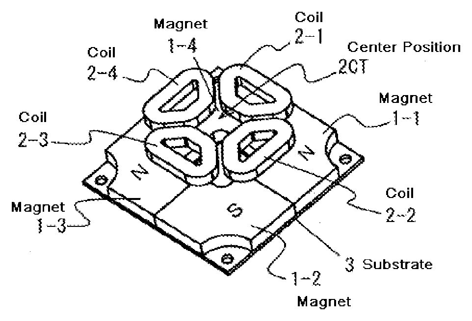
DESCRIPTION OF THE PREFERRED EMBODIMENTS In a direction indicator system in accordance with the present invention, a flat-type electromagnetic drive actuator is used. This electromagnetic drive actuator has a moving part that can slide back and forth, side to side, and diagonally. In the following, this electromagnetic drive actuator is first described, and examples of direction indicator devices that use this electromagnetic drive actuator are then described, with reference to the accompanying drawings. In the electromagnetic drive actuator, the moving part (hereinafter referred to as the key top) for stimulating the tactual sensation of the operator (user) at his/her hand or fingers is designed to slide back and forth, side to side, and diagonally. Referring to the accompanying drawings, the structure of the electromagnetic drive actuator is described. The Fleming's left-hand rule is applied to this electromagnetic drive actuator. More specifically, the key top is designed to move in a plane (to slide) by taking advantage of the electromagnetic force that is generated according to the Fleming's left-hand rule. FIGS. 1A through 1Cschematically show the structure of the electromagnetic drive actuator and the positional relationship among the components of the electromagnetic drive actuator.FIG. 1Ais a perspective view showing the relationship between four magnets1(1-1through1-4) and four coils2(2-1through2-4).FIG. 1Bis a plan view of the electromagnetic drive actuator.FIG. 1Cis a bottom view of the electromagnetic drive actuator. The four magnets1-1through1-4are fixed onto a substrate3that serves as a yoke. The four coils2-1through2-4are placed so as to face the magnets1. When the current to be supplied to the coils2is controlled, the coils2are two-dimensionally (in-plane) moved relative to the magnets1, while facing the magnets1. In other words, the coils are designed to slide relative to the magnets1. The magnets1may be permanent magnets or electromagnets. In a case where permanent magnets are employed, few magnets may be ...
DESCRIPTION OF THE PREFERRED EMBODIMENTS
In a direction indicator system in accordance with the present invention, a flat-type electromagnetic drive actuator is used. This electromagnetic drive actuator has a moving part that can slide back and forth, side to side, and diagonally. In the following, this electromagnetic drive actuator is first described, and examples of direction indicator devices that use this electromagnetic drive actuator are then described, with reference to the accompanying drawings.
In the electromagnetic drive actuator, the moving part (hereinafter referred to as the key top) for stimulating the tactual sensation of the operator (user) at his/her hand or fingers is designed to slide back and forth, side to side, and diagonally. Referring to the accompanying drawings, the structure of the electromagnetic drive actuator is described. The Fleming's left-hand rule is applied to this electromagnetic drive actuator. More specifically, the key top is designed to move in a plane (to slide) by taking advantage of the electromagnetic force that is generated according to the Fleming's left-hand rule.
FIGS. 1A through 1Cschematically show the structure of the electromagnetic drive actuator and the positional relationship among the components of the electromagnetic drive actuator.FIG. 1Ais a perspective view showing the relationship between four magnets1(1-1through1-4) and four coils2(2-1through2-4).FIG. 1Bis a plan view of the electromagnetic drive actuator.FIG. 1Cis a bottom view of the electromagnetic drive actuator. The four magnets1-1through1-4are fixed onto a substrate3that serves as a yoke. The four coils2-1through2-4are placed so as to face the magnets1. When the current to be supplied to the coils2is controlled, the coils2are two-dimensionally (in-plane) moved relative to the magnets1, while facing the magnets1. In other words, the coils are designed to slide relative to the magnets1. The magnets1may be permanent magnets or electromagnets. In a case where permanent magnets are employed, few magnets may be combined, or magnetic poles may be formed in a magnetic material by performing a magnetizing operation. For example, as the magnets1shown inFIG. 1B, two magnets may be employed, or four magnetic poles may be formed in a magnetic material through a magnetizing operation. In the structure shown inFIGS. 1A through 1C, the coils2may be fixed, and the magnets1may be moved. In the example described below, however, the magnets1are fixed, and coils2are moved.
FIGS. 2 and 3illustrate an electromagnetic drive actuator (hereinafter referred to as the actuator AT) in greater detail. InFIGS. 2 and 3, the components equivalent to those shown inFIGS. 1A through 1Care denoted by the same reference numerals as those inFIGS. 1A through 1C.FIG. 2is an external perspective view of the actuator AT in an assembled state.FIG. 3is an exploded perspective view of the actuator AT. As will be described later, the actuator AT is incorporated into a device or apparatus such as an electric wheelchair, a walking stick, or a game controller. The actuator AT is in the form of a driver component that slides based on direction indicator information provided from the outside.
The actuator AT is formed on a lower yoke3that functions as the substrate. Magnets1that are the same as the magnets1shown inFIGS. 1A through 1Care placed on the lower yoke3. A frame4is also provided on the lower yoke3, and support pillars5that functions as spacers and supporting members stand at the four corners of the frame4. The support pillars5form a predetermined space above the lower yoke3, and an upper yoke6is placed on the support pillars5. A slider10having the coils2fixed thereto is movably accommodated in the space formed between the upper and lower yokes3and6. The slider10is designed to slide two-dimensionally with the thrust force that is generated between the coils2and the magnets1when a current is supplied to the coils2. A guide mechanism is formed on the upper yoke6. The guide mechanism is designed to move the slider10in a predetermined two-dimensional region (X-Y plane movement).
The slider10holds the coils2under its lower face. The coils2are fixed to the lower face of the slider10with a coil holder11that is provided on the slider10. The coil holder11moves with the slider10. A protrusion12is formed on the upper face of the coil holder11. A key top13is engaged with the protrusion12. The key top13is accommodated in a hole6HL formed at the center of the upper yoke6. When the actuator AT is in an assembled state, the key top13protrudes from the upper face of the upper yoke6, as shown inFIG. 2. The key top13is placed in the center position2CT (seeFIGS. 1A and 1B) of the coils2fixed to the lower face of the slider10. A circuit board is also interposed between the lower face of the slider10and the coils2. An electric part EP and the likes are placed in the circuit board, and a predetermined circuit pattern is formed on the circuit board.
A mechanism for moving the slider10in a predetermined two-dimensional region is formed on the upper yoke6. This moving mechanism is now described. In the actuator AT of this example, the key top13that moves with the slider10is engaged with a guide member, so that the slider10moves in the predetermined two-dimensional region.
To guide the key top13in the X-axis direction and the Y-axis direction, the actuator AT has a first guide member16and a second guide member17. As shown inFIG. 3, the first guide member16guides the key top13within a predetermined range in the Y-axis direction. The first guide member16has a rectangular hole16HL at its center, and this hole16HL accommodates the key top13. With this arrangement, the first guide member16guides the key top13in the Y-axis direction.
Further, the first guide member16is guided in the X-axis direction, which is perpendicular to the Y-axis direction, by the second guide member17. The second guide member17accommodates the first guide member16in a hole17HL, so as to guide the first guide member16in the X-axis direction.
In the above described structure, the key top13is guided in the Y-axis direction by the first guide member16, and the first guide member16is guided in the X-axis direction, which is perpendicular to the Y-axis direction, by the second guide member17. Accordingly, when the slider10having the coils2is subjected to predetermined thrust force, the key top13slides in the two-dimensional region (the X-Y plane). More specifically, the current to be supplied to the four coils2(2-1through2-4) is controlled, so that the key top13slides in the Y-axis direction (back and forth) and the X-axis direction (from side to side) perpendicular to the Y-axis direction, and a diagonal direction formed as a combination of those two directions.
By controlling the electric signal to be supplied to the coils2, the above described actuator AT can cause the key top13to slide back and forth, from side to side, and diagonally. Accordingly, the actuator AT is incorporated into a device or apparatus, so as to form a direction indicator system that can present a desired direction by stimulating the tactual sensation at a hand or a finger of the operator with the key top13. More specifically, the current to be supplied to the coils2is controlled, and the key top13is caused to slide in the direction to be presented, so that the operation can recognize the desired direction. Further, the sliding operation is repeated, so as to make sure that the operator recognizes the desired direction.
The following is a description of an electric wheelchair and a walking stick that have route guide functions, and a game controller that has a function for aiding disabled people. A direction indicator system that includes the above described actuator AT is applied to those devices as embodiments of the present invention.
[First Embodiment]
FIG. 4illustrates an electric wheelchair MW in accordance with a first embodiment that employs the actuator AT. The actuator AT is used as the operation unit WR of the electric wheelchair MW. InFIG. 4, the operation unit WR is shown in an enlarged view in an ellipse. The operation unit WR has a stick-like shape. For example, the operation unit WR is tilted in a desired direction, the electric wheelchair MW can be moved. The actuator AT is embedded in the upper end portion of the operation unit WR. When an operator grabs the operation unit WR, his/her thumb should touch the key top13of the actuator AT. Accordingly, when the key top13slides in a predetermined direction, the operator can sense the movement through stimulation of the tactual sensation.
FIG. 5is a block diagram showing the structure for controlling the actuator AT that indicates the traveling direction of the electric wheelchair MW. The electric wheelchair MW includes a position information processor PF-P that serves as a navigation unit for identifying the traveling direction by detecting a route, and a drive controller DC-P that controls the actuator AT, based on a signal supplied from the position information processor PF-P.
Like a vehicle having a navigation device mounted therein, the electric wheelchair MW receives a GPS (Global Positioning System) signal, recognizes its own position, and then identifies the subject route. The position information processor PF-P shown inFIG. 5obtains current position information from a position information provider of the outside, and functions as a navigation device that guides the operator through the route to the destination that is set in advance with the use of map information. The position information processor PF-P has an external information processor and an operation CPU (Central Processing Unit). The external information processor checks its own position by receiving a GPS signal. The operation CPU checks its own position with the use of map information that is provided in the CPU, and searches for and determines the route to the destination. The operation CPU then outputs a signal in accordance with the determined route.
The drive controller DC-P functions as a drive controlling unit that controls the actuator AT, based on a signal supplied from the position information processor PF-P. More specifically, based on a signal supplied from the operation CPU, The drive controller DC-P causes the key top13of the actuator AT to slide in the direction in which the electric wheelchair MW is about to move. The drive controller DC-P includes a power circuit, a voltage regulator circuit, and a transmitter circuit.
The position information processor PF-P and the drive controller DC-P are driven by a mounted battery that is provided to drive the wheelchair driving motor, as shown inFIG. 5.
FIGS. 6A through 6Cshow examples of voltage waveforms that are observed when the drive controller DC-P controls the drive of the actuator AT in accordance with a signal supplied from the position information processor PF-P.FIG. 6Ashows a voltage waveform observed when the key top13of the actuator AT is caused to slide in a reciprocating manner in the X-axis direction (the transverse direction of the electric wheelchair, for example) in a short period of time.FIG. 6Bshows a voltage waveform observed when the key top13is caused to slide in a reciprocating manner at timewise intervals.FIG. 6Cshows a voltage waveform observed when the key top13is caused to slide to and stay at the right side, and then return to the original position. Those actions are linked beforehand to the information about the directions to be indicated, so that the tactual sensation of the operator can be stimulated, and the operator can notice each indicated direction. As for the Y-axis direction, the same waveforms as above are formed for the voltage to be controlled, and the key top13is moved in a sliding manner, so as to stimulate the tactual sensation of the operator and to inform the operator of the desired direction.
FIGS. 7A and 7Bshow examples of sliding actions of the actuator AT in a case where the X-axis direction and the Y-axis direction are combined.FIG. 7Ashows a case where a positive voltage is applied only in the Y-axis direction, so as to cause the key top13of the actuator AT to slide forward in a direction parallel to the traveling direction. In the case shown inFIG. 7A, the key top13slides in a direction parallel to the traveling direction, stays at the front end for a certain period of time, and then returns to the center position. This sliding action is linked beforehand to straight movement, so as to stimulate a thumb of the operator and to inform the operator of the traveling direction. Likewise,FIG. 7Bshows a case where a positive voltage is applied in the X-axis direction and the Y-axis direction. The key top13of the actuator AT slides diagonally forward and rightward with respect to the traveling direction, and stays at the front end for a certain period of time. This sliding action is linked beforehand to the rightward diagonal movement.
FIG. 8shows the moving direction guiding operation to be performed by the position information processor PF-P and the drive controller DC-P shown inFIG. 5in cooperation with each other. In the block diagram shown inFIG. 5, the operation CPU of the position information processor PF-P and the drive controller DC-P are shown separately from each other, to facilitate understanding of the invention. However, the position information processor PF-P and the drive controller DC-P may be realized by a CPU.
As described above, the position information processor PF-P has the same functions as a navigation device. Although not shown in the drawings, an input device for inputting a destination is installed in the electric wheelchair. When a destination is input (S1), the external information receiving unit of the position information processor PF-P receives position information (such as a GPS signal) from the outside (S2). The operation CPU then checks the inside map data (map information) for the present position (S3) and check the destination (S4), and then carries out a search for the information about the route from the present position to the destination (S5).
After the route from the present position of the electric wheelchair MW to the destination is determined in the above described manner, the wheelchair MW reaches a turning point (a cross point) (S6), and the operation CPU converts traveling direction information into the X- and Y-axis voltage waveform data (S7). The voltage waveform data is transferred to the drive controller DC-P (S8), and the drive controller DC-P applies a predetermined voltage to the actuator AT (S9). As a result, the key top13performs an action such as a sliding action in a direction parallel to the traveling direction (S10). This sliding action stimulates the fingers of the operator grabbing the operation unit of the electric wheelchair MW. Thus, the operator can be certainly notified of the indicated direction through the stimulation of tactual sensation.
The electric wheelchair MW having the above described navigation function uses an actuator to indicate the traveling direction by stimulating the tactual sensation of the operator. In this manner, the operator can be informed of a direction through tactual sense, instead of the visual or auditory sense. Particularly, as the device for simulating the tactual sensation, the electromagnetic drive actuator AT that has the key top13sliding in a plane is used. With the actuator AT, the traveling distance is set at a predetermined length or more, so that the tactual sensation of the operator is stimulated at a hand or fingers. Thus, the operator can be certainly notified of the indicated direction only through the tactual sense.
(First Modification)
The following is a description of a modification of the first embodiment.FIG. 9is a block diagram showing a first modification of the first embodiment. In this block diagram, components equivalent to the components shown inFIG. 5are shown. As shown inFIG. 9, an obstacle sensor BS is added in the first modification, and a detection signal is supplied from the obstacle sensor BS to the operation CPU. As the obstacle sensor BS, a ultrasonic sensor, an optical sensor, or millimeter-wave radar for detecting obstacles in the surroundings may be provided in the electric wheelchair MW.
FIG. 10shows the traveling direction guiding operation of the first embodiment that is improved by employing the obstacle sensor to avoid obstacles located in the traveling direction. The procedures of the first half of the operation shown inFIG. 10are the same as the procedures of the first half (S1through S6) of the flowchart showing the traveling direction guiding operation inFIG. 8. Therefore, the procedures of the last half are described below as steps S21through S26.
If the obstacle sensor BS detects an obstacle (S21) when the electric wheelchair MW reaches a turning point (S6), the operation CPU receives the detection signal (S22). The operation CPU converts the obstacle information into the X- and Y-axis voltage waveform data (S23). The voltage waveform data is transferred to the drive controller DC-P (S24), and the drive controller DC-P applies a predetermined voltage to the actuator AT (S25). In this case, the actuator AT vibrates or performs such an action as to make the operator feel a click. In this manner, the operator is informed of the existence of the obstacle (S26). If the traveling can be continued by informing the operator of the existence of the obstacle, a regular sliding action may be performed thereafter, so as to inform the operator of the changed traveling direction. If the traveling cannot be continued due to the obstacle, it is preferable that a predetermined warning is issued.
(Second Modification)
A second modification of the first embodiment is now described.FIG. 11shows an electric wheelchair MW in accordance with the second modification in which the actuator AT is placed in the armrest AR on the opposite side from the operation unit WR. In the above described embodiment, the actuator AT is incorporated into the lever of the operation unit WR. In such a case, the placement position of the actuator AT is limited, and the actuator AT needs to be small. On the other hand, in the case illustrated inFIG. 11, the actuator AT is placed in the armrest AR on the opposite side from the operation unit WR. In this manner, a certain degree of freedom is allowed in the design and placement of the actuator AT. In the case of the second modification shown inFIG. 11, the tactual sensation of the operator is stimulated not only at his/her fingers, but also at his/her palm, his/her arm, or his/her elbow, when the operator is informed of the direction.
(Third Modification)
A third modification of the first embodiment is now described.FIG. 12shows the third modification in which the actuator AT is detachably formed. In the third modification, a first electric contact CT-1is formed in the actuator AT. A second contact CT-2to face the first contact CT-1and a structure for supporting the actuator AT are provided at the upper end of the operation unit WR. Likewise, a third contact CT-3to face the first contact CT-1and a structure for supporting the actuator AT are also provided in the armrest AR.
With the structure in accordance with the third modification shown inFIG. 12, the actuator AT can be attached and detached in accordance with a request from the operator who is using the electric wheelchair MW. As the actuator AT is detachable, any specific disabled part of the operator can be coped with. If the operator is a person who has lost his/her left arm, the actuator AT is placed at the operation unit WR. If the operator is a person who has disabled right-hand fingers, the actuator AT is placed in the armrest AR. In accordance with the condition and a request of the operator, the location of the actuator in the electric wheelchair MW in accordance with the third modification can be changed. Accordingly, the electric wheelchair MW can be shared by two or more persons. The location of the actuator shown inFIG. 12is merely an example. For example, the actuator may be placed on the step ST on which the operator puts his/her feet. The third modification provides a structure in which the actuator AT is made detachable so that the location of the actuator AT can be changed. However, it is also possible to place the actuator AT in a slidable fashion so that the location of the actuator AT can be changed within a predetermined area.
[Second Embodiment]
A second embodiment of the present invention is now described. In the second embodiment, the same structure as the structure employed in the electric wheelchair MW of the first embodiment is employed in a walking stick. In the following description of the second embodiment, the same components as those of the first embodiment are denoted by the same reference numerals as those used in the first embodiment, and explanation of them is omitted here.FIG. 13shows a white stick WS for a visually-impaired person in accordance with the second embodiment. This white stick WS has the function of indicating a direction. Like the electric wheelchair MW of the first embodiment, the white stick WS has a navigation function, and stimulates the tactual sensation of a visually-impaired person at his/her hand through a sliding action of the actuator AT, so as to inform the person of the traveling direction or the like. More specifically, the actuator AT is set at the top end of a gripping part GP at the upper portion of the white stick WS. With this arrangement, the key top13can stimulate the tactual sensation of the user at his/her thumb, so as to inform the user of the direction. Concave portions CS that can be sensed as the finger gripping points by the user are formed on the gripping part GP of the white stick WS. When the white stick WS is used, the orientation of the stick WS stays the same, and the user can be informed of the direction through a sliding action of the key top13.
FIG. 14is a block diagram showing the structure for controlling the drive of the actuator AT that is set on the white stick WS. In the case of the electric wheelchair MW of the first embodiment, all the components such as the driving battery, the position information processor PF-P having the navigation function, and the drive controller DC-P for controlling sliding actions of the actuator AT can be mounted on the electric wheelchair MW. In the case of the white stick WS of the second embodiment, on the other hand, the space is limited. Therefore, the actuator AT, the drive controller DC-P for controlling the drive of the actuator AT, and a receiver are set in a small space on the stick. Meanwhile, the position information processor PF-P is formed separately from the other components, and is designed to transmit driving signals for the actuator AT. The position information processor PF-P formed separately from the other components may be designed as an independent device, but it is more preferable that the position information processor PF-P is formed as a function of a portable telephone device or a PDA (Personal Digital Assistant), for example. The user of the white stick WS or a person accompanying the user carries the position information processor PF-P designed as above, so that the white stick WS can be used in the same manner as the electric wheelchair MW.
(First Modification)
The following is a description of a modification of the second embodiment.FIG. 15shows a first modification of the second embodiment in which the actuator AT is placed at a side of the gripping part GP. As shown inFIG. 15, the actuator AT is placed on the opposite side from the concave portions CS to be gripped by the user. With this arrangement, the tactual sensation is stimulated at a thumb or a palm of the user. In a case where the actuator AT is placed vertically as in this modification, it is necessary to determine in advance that the top represents the forward direction and the bottom represents the backward direction, for example.
(Second Modification)
A second modification of the second embodiment is now described.FIG. 16shows the second modification in which a structure for moving the actuator AT is provided on the gripping part GP. More specifically, the gripping part GP has a guiding part30for movement and a screw part31for fixing the actuator AT at a desired location. With the white stick WS of this modification, the location of the actuator AT can be changed in accordance with the physical condition or the preference of the user. Since the location of the actuator AT can be changed in accordance with the condition or a request of the user, the white stick WS can be shared by two or more persons.
(Third Modification)
A third modification of the second embodiment is now described.FIG. 17shows the third modification in which the actuator AT is made detachable. In the third modification, a first electric contact CT-1is formed on the actuator AT. A second contact CT-2for allowing the first contact CT-1to be attached and detached is provided at the top end of the gripping part GP of the white stick WS, and a third contact CT-3for allowing the first contact CT-1to be attached and detached is provided at a side of the gripping part GP. In the white stick WS of the third modification, the location of the actuator AT can be changed in accordance with the condition or a request of the user. Since the location of the actuator AT can be changed in accordance with the condition or a request of the user, the white stick WS of this modification can be shared by two or more persons.
[Third Embodiment]
Referring now toFIGS. 18A and 18B, a third embodiment of the present invention is described. The third embodiment relates to a game controller.FIGS. 18A and 18Billustrate a game controller GC in accordance with this embodiment.FIG. 18Ais an external perspective view of the game controller GC in use.FIG. 18Bis a cross-sectional side view of the game controller GC. As shown inFIG. 18A, this game controller GC is connected to a game console40, and is used to control a game displayed on a display device45.
The player of a game normally handles a joystick JS and an input button BT on the game controller GC in accordance with the application software that is set in the game console40. As shown inFIG. 18B, the actuator AT is used at the base portion of the joystick JS of the game controller GC. Also, a circuit that checks the direction indicating information in accordance with the contents of the application software and generates the X- and Y-axis voltage waveform data based on the direction indicating information is installed in the game console40. Accordingly, with an output signal from the game console40being used as drive instructing information, the key top13of the actuator AT in the game controller GC can be moved in a sliding manner.
For example, when a car racing game for simulating a vehicle running on roads is used as the application software, the joystick JS of the game controller GC is caused to slide side to side, so as to stimulate the tactual sensation of the player at his/her palm or the like. Such a game controller GC can be suggested as an assisting device for a player who is visually impaired, or as an assisting function for a young child to experience a game.
As described above, the present invention can provide a direction indicator system that stimulates the tactual sensation of a user with the use of a simple structure, and can certainly indicate a direction based on direction indicating information. An electric wheelchair, walking stick, or game controller that employs this system can certainly inform the user of the indicated direction. Thus, a user-friendly device or apparatus can be provided.
Although a few preferred embodiments of the present invention have been shown and described, it would be appreciated by those skilled in the art that changes may be made in these embodiments without departing from the principles and spirit of the invention, the scope of which is defined in the claims and their equivalents.
The present application is based on Japanese Patent Application No. 2007-015421 filed Jan. 25, 2007, the entire disclosure of which is hereby incorporated by reference.
Claims
- A direction indicator system comprising: an electromagnetic drive actuator that has a moving part that stimulates tactile sensation of an operator at his/her hand or fingers by sliding back and forth, side to side, and diagonally, the moving part sliding in a given two-dimensional region;a drive controlling unit that controls a sliding direction of the moving part, based on direction indicating information that is supplied from the outside and;an obstacle sensor that detects an obstacle existing in a traveling direction, wherein the drive controlling unit changes the control of the electromagnetic drive actuator in accordance with obstacle information supplied from the obstacle sensor.
- The direction indicator system as claimed in claim 1 , further comprising a navigation unit that obtains current position information from a position information provider of the outside, wherein the drive controlling unit controls the electromagnetic drive actuator, based on route information that is provided as the direction indicating information by the navigation unit.
- An electric wheelchair comprising the direction indicator system as claimed in claim 2 .
- The electric wheelchair as claimed in claim 3 , wherein the electromagnetic drive actuator is placed in an operation part for driving operations or in an armrest.
- The electric wheelchair as claimed in claim 3 , wherein the electromagnetic drive actuator is placed in an operation part for driving operations or in an armrest, the electromagnetic drive actuator being located in a variable position or being detachable.
- A walking stick comprising the direction indicator system as claimed in claim 2 .
- The walking stick as claimed in claim 6 , wherein the electromagnetic drive actuator is placed on an upper portion or a side portion of a gripping part.
- The walking stick as claimed in claim 6 , wherein the electromagnetic drive actuator is located in a variable position in the gripping part or is detachable from the gripping part.
- The walking stick as claimed in claim 6 , wherein concave portions for indicating a gripping position are formed on a gripping part.
- A game controller comprising the direction indicator system as claimed in claim 1 , wherein the drive controlling unit controls the electromagnetic drive actuator, based on the direction indicating information that is supplied from a game console.
- A method of indicating a direction, comprising: sliding a moving part of an electromagnetic drive actuator back and forth, side to side, and diagonally in a given two-dimensional region;stimulating tactile sensation of an operator at his/her hand or fingers;supplying direction indicating information from the outside;controlling a sliding direction of the moving part based on the direction indicating information;detecting an obstacle existing in a traveling direction;and changing the control of the moving part in accordance with information about the obstacle.
- A direction indicator system comprising: an electromagnetic drive actuator that has a moving part that can stimulate tactual sensation of an operator at his/her hands or fingers by sliding back and forth, side to side, and diagonally, the moving part sliding in a given two-dimensional region;a drive controlling unit that controls a sliding direction of the moving part, based on direction indicating information that is supplied from the outside;and an obstacle sensor that detects an obstacle existing in a traveling direction, wherein the drive controlling unit changes the control of the electromagnetic drive actuator in accordance with obstacle information supplied from the obstacle sensor, wherein the moving part is fixed to a slider that moves with a coil placed so as to face magnets fixed onto a substrate.
Disclaimer: Data collected from the USPTO and may be malformed, incomplete, and/or otherwise inaccurate.