Illustrative Figure
Abstract
A video game accessory comprises a body configured to receive a video game controller at a first location of the body, receive a controller expansion device connectable to the video game controller at a second location of the body, and maintain the orientation of the controller expansion device so that the orientation of the controller expansion device is substantially fixed with respect to an orientation of the video game controller, and a pass through cable comprising a first end that includes a first connector and a second end that includes a second connector, the pass through cable extending from the first location to the second location, wherein the first connector is engageable with a first mating connector of the video game controller and the second connector is engageable with a second mating connector of the controller expansion device.
Description
DETAILED DESCRIPTION In general, this disclosure is directed to a video game accessory that may be used with a video game controller and a controller expansion device for a video game system. In one example, the video game accessory comprises a body that receives the video game controller and the controller expansion device and electrically couples the controller and the accessory with a pass through cable. The video game accessory with the pass through cable allows the video game controller and controller expansion device to be placed separate from one another when associated with the video game accessory, which in turn allows for desirable placement of the video game controller within the video game accessory to allow for easy access and manipulation of controls (e.g., buttons, directional pads, and/or joysticks used to control action within a video game) of the video game controller by the video game user (also referred to herein as “video game player,” “player,” or “gamer”). The video game accessory also allows for controlled placement of both the video game controller and the controller expansion device to provide for a particular balance and weight distribution in order to achieve a desired effect for the player. FIGS. 1 and 2show several views of a video game accessory10according to an example of the present invention. In one example, video game accessory10comprises a body12that is configured to receive a video game controller14(shown inFIG. 3, also referred to herein as “controller14”) at a first location16. Body12is also configured to receive a controller expansion device18(shown inFIG. 4, also referred to herein as “expansion device18”) at a second location20and to maintain the orientation of expansion device18so that the orientation of controller expansion device18is substantially fixed with respect to the orientation of video game controller14. Controller expansion device18is electrically connectable to video game controller14. ...
DETAILED DESCRIPTION
In general, this disclosure is directed to a video game accessory that may be used with a video game controller and a controller expansion device for a video game system. In one example, the video game accessory comprises a body that receives the video game controller and the controller expansion device and electrically couples the controller and the accessory with a pass through cable. The video game accessory with the pass through cable allows the video game controller and controller expansion device to be placed separate from one another when associated with the video game accessory, which in turn allows for desirable placement of the video game controller within the video game accessory to allow for easy access and manipulation of controls (e.g., buttons, directional pads, and/or joysticks used to control action within a video game) of the video game controller by the video game user (also referred to herein as “video game player,” “player,” or “gamer”). The video game accessory also allows for controlled placement of both the video game controller and the controller expansion device to provide for a particular balance and weight distribution in order to achieve a desired effect for the player.
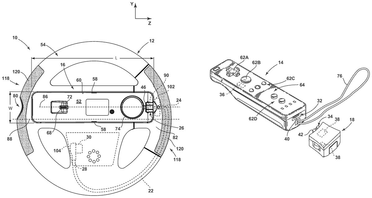
FIGS. 1 and 2show several views of a video game accessory10according to an example of the present invention. In one example, video game accessory10comprises a body12that is configured to receive a video game controller14(shown inFIG. 3, also referred to herein as “controller14”) at a first location16. Body12is also configured to receive a controller expansion device18(shown inFIG. 4, also referred to herein as “expansion device18”) at a second location20and to maintain the orientation of expansion device18so that the orientation of controller expansion device18is substantially fixed with respect to the orientation of video game controller14. Controller expansion device18is electrically connectable to video game controller14. Video game controller14at first location16is electrically connected to controller expansion device18at second location via a pass through cable22(FIG. 5) that electrically connects controller14to expansion device18.
Body12comprises a shape selected to enhance the realism of game play for the player. In one example, shown inFIGS. 1,2,5and6, body12has the shape of a steering wheel. As such, the remainder of the present disclosure refers to body12as steering wheel12. However, other configurations of body12are possible in accordance with the present invention. For example, video game accessory10may comprise a body having any of the following example shapes: an airplane controller to simulate a flight stick for flight simulation games; a frying pan, spatula or other cooking utensil for a cooking simulation game; a racquet, Frisbee disc, baseball bat, golf club, fishing rod, or other sports accessory for sports games; a gun or “zapper” for shooting games; a sword or sword hilt for sword fighting games; and guitars or other musical instruments for music games.
Pass through cable22(also referred to herein as “cable22,” shown schematically inFIGS. 5 and 6) provides for an electrical connection between video game controller14at first location16and controller expansion device18at second location20. Pass through cable22comprises a first end24that includes a first connector26and a second end28that includes a second connector30. First connector26engages a mating connector32of video game controller14(shown inFIG. 7) while second connector30engages a mating connector34of controller expansion device18(shown inFIG. 7). Pass through cable22facilitates communication of electrical signals between first connector26and second connector30, and thus provides for electrical communication between video game controller14engaged with first connector26and controller expansion device18engaged with second connector30. In one example, pass through cable22allows for passive electrical pass through of electrical signals between first connector26and second connector30. However, a signal amplifier (not shown) may be included to boost electrical signals passing through cable22if it is found that the signals are unacceptably weakened during transmission through cable22.
In one example, video game controller14comprises a controller compatible with the Nintendo Wii video game system, sometimes referred to as a Wii Remote14, and controller expansion device18comprises an expansion device that is compatible with the Wii Remote, such as the Wii MotionPlus expansion device18. A depiction of a Wii Remote14that is installed with body12is shown inFIG. 3. A depiction of a Wii MotionPlus expansion device18that is installed with body12is shown inFIG. 4. In one example, video game controller14includes a motion sensor36that senses motion (shown schematically inFIG. 7). Motion sensor36may comprise an accelerometer, such as a three-axis linear ADXL330 accelerometer manufactured by Analog Devices, Inc. of Norwood, Mass. that is used in the Wii Remote14. Expansion device18may supplement motion sensing of controller motion sensor36using one or more motion sensors38(shown schematically inFIG. 7), such as a gyroscope sensor, for example, the IDG-600 or IDG-650 multi-axis gyroscope sensor manufactured by InvenSense Inc. of Sunnyvale, Calif. and the X3500W vibration gyroscope sensor manufactured by Epson Toyocom Corp. of Hino, Tokyo, Japan that are used in the Wii MotionPlus device18.
The Wii MotionPlus device18is designed to electrically connect to the Wii Remote14directly, as shown inFIGS. 7 and 8. Wii Remote14includes a mating connector32, also referred to as expansion connector32, which comprises a female connector port40for receiving a complementary mating male connector portion42, such as connector34of Wii MotionPlus device18. Male connector34of Wii MotionPlus device18is inserted into female expansion connector32of Wii Remote14to electrically connect Wii Remote14to Wii MotionPlus device18. Connectors32and34also allow for the alignment of the orientation of Wii Remote14to the orientation of Wii MotionPlus device18so that the devices are generally in line with one another. When Wii MotionPlus device18is electrically connected to Wii Remote14, the two devices are calibrated to provide a baseline for the video game system to know the relative position and orientation of Wii Remote14and Wii MotionPlus device18. A locking mechanism44ensures that Wii MotionPlus device18remains in the same relative position and orientation with respect to Wii Remote14.
In the example where controller14is a Wii Remote and expansion device18is a Wii MotionPlus device, first connector26on first end24of pass through cable22has the same configuration as mating connector34of Wii MotionPlus device18, e.g., first connector26comprises a male connector portion46, as shown inFIG. 1, that is insertable into female port40of mating connector32of Wii Remote14. Second connector30on second end28of cable22may have the same configuration as mating connector32of Wii Remote14, e.g., second connector30may comprise a female connector port48, shown inFIG. 9, that can receive male connector portion42of mating connector34of Wii MotionPlus device18. In this way, first connector26simulates the mating connector34of expansion device18that is engagable with mating connector32of video game controller14, while second connector30simulates the mating connector32of controller14that is engagable with mating connector34of controller expansion device18. Although first connector26and second connector30are described as a male connector and female connector, respectively, the configurations of first connector26and second connector30may be switched. The type of connector used at each end24,28of cable22will depend on the type of connection needed to video game controller14and expansion device18. The remainder of the present disclosure is described in the context of first connector26being a male connector that engages a female mating connector32of controller14and in the context of second connector30being a female connector that engages a male mating connector34of expansion device18. However, modification to the configurations of first connector26, second connector30, controller mating connector32, and expansion device mating connector34could be made if a different connector arrangement is desired for a particular application or use.
If a video game accessory is to be used with a controller14and an expansion device18, such as a Wii MotionPlus expansion device with a Wii Remote, it may be desirable to secure the orientation of expansion device18with respect to the orientation of controller14. In the example video game accessory10shown inFIGS. 1-6, steering wheel12is configured to maintain the orientation of controller expansion device18so that the orientation of controller expansion device18is substantially fixed with respect to an orientation of video game controller14. In one example, the relative orientations of video game controller14and expansion device18are substantially fixed because steering wheel12is configured to maintain the orientation of video game controller14with respect to the orientation of steering wheel12and to maintain the orientation of controller expansion device18with respect to the orientation of steering wheel12so that the orientation of expansion device18is substantially fixed with respect to the orientation of video game controller14. In one example, steering wheel12is configured to secure video game controller14in an orientation that is substantially fixed with respect to the orientation of steering wheel12. Steering wheel12may also be configured to secure controller expansion device18in an orientation that is substantially fixed with respect to steering wheel12so that the orientation of expansion device18is substantially fixed with respect to the orientation of video game controller14.
The use of the phrase “substantially fixed with respect to the orientation,” or similar language, in the present disclosure means that the final relative orientations of the two components are substantially fixed before use. However, a substantially fixed orientation is not intended to limit the two components to any particular relative orientation. For example, although the figures generally show video game controller14and controller expansion device18having a generally parallel orientation, e.g., with the longitudinal axis of each device being oriented generally in the same direction (such as both being oriented to be substantially parallel to the x direction of the orthogonal x-y axes shown inFIGS. 3 and 4), other relative orientations could be used. For example, expansion device18could be generally orthogonal to video game controller14(e.g., with the longitudinal axis of expansion device18oriented generally in the y direction while the longitudinal axis of controller14is oriented generally in the x direction) or expansion device18could be oriented at an angle with respect to controller14. In the example of a Wii Remote controller14and a Wii MotionPlus expansion device18, steering wheel12is preferably configured so that the orientation of Wii Remote14is generally parallel to MotionPlus expansion device18, more preferably substantially parallel or even exactly parallel, so that MotionPlus expansion device18will accurately detect and report roll of steering wheel12. The orientation of expansion device18is “substantially fixed” with respect to the orientation of controller14when the selected relative orientation does not substantially change during game play by the player.
In one example, shown inFIGS. 1 and 2, steering wheel12comprises a controller compartment50for receiving video game controller14and an expansion device compartment52for receiving controller expansion device18. Controller compartment50is configured to secure video game controller14in an orientation that is substantially fixed with respect to an orientation of steering wheel12. Similarly, expansion device compartment52is configured to secure controller expansion device18in an orientation that is substantially fixed with respect to the orientation of steering wheel12, which in turn causes the orientation of expansion device18to be substantially fixed with respect to the orientation of video game controller14. In one example, steering wheel12is configured to generally have a front side54and a back side56(FIGS. 1,2, and11), wherein controller compartment50is located at front side54and is accessible from front side54while expansion device compartment52is located at back side56and is accessible from back side56.
In one example, controller compartment50has the same general shape as video game controller14and is dimensioned to be slightly larger than video game controller14so that the orientation of controller14is maintained, at least somewhat, by a close fit between controller14and controller compartment50. In one example, wherein video game controller14is a Wii Remote, which is about 148 mm (about 5.83 inches) long and about 36.2 mm (about 1.43 inches) wide, controller compartment50has a length L (FIG. 5) of about 151 mm (about 5.94 inches) and a width W (FIG. 5) of about 36.5 mm (about 1.44 inches) with a manufacturing tolerance of plus-or-minus about 0.05 mm (about 0.002 inches). As described in more detail below, controller compartment50is also configured to place first connector26so that it will engage mating connector32of controller14when video game controller14is installed in controller compartment50.
In one example, steering wheel12also comprises one or more compression pads58mounted on an inner wall60of controller compartment50, as shown inFIGS. 1 and 5. Compression pads58extend inwardly slightly into controller compartment50from inner wall60, such as between about 1 mm and about 3 mm, so that when video game controller14is inserted into controller compartment50, compression pads58are deformed by controller14to create a compression fit and/or grip between controller14and inner wall60. Compression pads58act to further fix the orientation of video game controller14with respect to the orientation of steering wheel12. In one example, the one or more compression pads58comprise a resilient material that is temporarily deformed by video game controller14, but that can return to its original shape upon removal of controller14from controller compartment50. Examples of resilient materials that may be used for compression pads58include silicon, natural or synthetic rubbers, for example polyisoprene, Neoprene, or silicone rubber, and other elastomeric polymers.
Video game controller14comprises a plurality of gaming controls, such as direction pad62A, control buttons62B,62C,62D, and trigger62E (FIGS. 7 and 8) (collectively referred to herein as “gaming controls62” or “controls62”). Steering wheel12is configured to allow access to all gaming controls62that are necessary for the video game for which it is intended to be used, and preferably the body of steering wheel12is configured to provide access to all gaming controls62. In the example of the Wii Remote14, most gaming controls62are provided on a front side64of Wii Remote14(seeFIG. 7) so that access to these controls62(e.g., direction pad62A and control buttons62B,62C,62D) is accomplished by having a generally open front of controller compartment50so that gaming controls62are not covered, as shown inFIG. 3. Wii Remote14also comprises a trigger62E located on a back side66of Wii Remote14(shown inFIG. 8). In one example, steering wheel12comprises a trigger opening68into controller compartment50to provide access to trigger62E, which might otherwise be covered by steering wheel12. In one example, steering wheel12also comprises a trigger button70that extends out of back side56of steering wheel12. Trigger button70moves between a resting position and an actuated position. A tab72is included on trigger button70that may be inserted through trigger opening68and into controller compartment50to actuate trigger62E when button is moved from the resting position to the actuated position. In one example, trigger button70is biased into resting position, such as with a spring between steering wheel12and trigger button70, so that if trigger button70is not being pushed by a game player, it will return to the resting position.
Other access openings may be provided into controller compartment50, such as an opening74for a wrist strap76of controller14(shown inFIG. 7). In one example, video game controller14comprises a light port78, such as an infrared port for sensing infrared light (FIG. 8). Steering wheel12may comprise a light pass through opening80, shown inFIGS. 1 and 11, to allow for the passage of light to or from light port78.
FIG. 2shows expansion device compartment52without expansion device18andFIG. 4shows expansion device compartment52with expansion device18installed. In one example, expansion device compartment52receives expansion device18and is configured to secure controller expansion device18in an orientation that is substantially fixed with respect to the orientation of video game controller14. In one example, expansion device compartment is configured to secure expansion device18in an orientation that is substantially fixed with respect to the orientation of steering wheel12, as described in more detail below.
FIGS. 1,5, and12show a video game accessory10comprising a securing mechanism at controller compartment50for securing video game controller14in orientation that is substantially fixed with respect to the orientation of steering wheel12. In one example, the securing mechanism comprises a slider82that moves between an open position (FIG. 12) and a closed position (FIG. 5). When slider82is in the open position, video game controller14may be received by controller compartment50. When video game controller14is placed within controller compartment50and slider82is moved into the closed position (as inFIG. 3), video game controller14is secured within controller compartment50. Slider82may include a detent mechanism, such as a protrusion (not shown) on slider82that mates with a detent depression83on body12(FIG. 12), to hold slider82in either the open position or the closed position. Other types of detent mechanisms may be used. For example, a bearing may be used rather than a protrusion. Other configurations of the detent mechanism may also be used. For example, the detent protrusion may be located on body12while the detent depression may be located on slider82.
In one example, best seen inFIGS. 5 and 12, first connector26of pass through cable22is secured to slider82so that first connector26extends from slider82into controller compartment50when slider82is in the closed position. As shown inFIG. 5, before video game controller14is inserted into controller compartment50when slider82is in the closed position, first connector26extends into controller compartment50such that first connector26would interfere with the insertion of controller14into controller compartment50. When slider82is moved into the open position (FIG. 12), first connector26is moved out of the way, leaving enough space for controller14to be placed into controller compartment50. Once controller14is placed in controller compartment50, slider82may be slid from the open position to the closed position (FIG. 3). First connector26is positioned on slider82such that as slider82moves toward the closed position, first connector26is inserted into mating connector32of video game controller14. When slider82is moved into the closed position, first connector26is fully engaged with mating connector32so that an electrical connection is formed between video game controller14and pass through cable22. In addition, the engagement between first connector26secured on slider82and mating connector32of video game controller14acts to further secure video game controller14within controller compartment50by inhibiting the removal of controller14from controller compartment50.
As shown inFIGS. 3 and 5, in one example, video game controller14has a longitudinal axis84extending along its length and controller compartment50has a longitudinal axis86extending along its length. Steering wheel12has horizontal dimension88extending across its width (e.g., the diameter of steering wheel12that is extending generally in the x direction of the orthogonal x-y axes shown inFIG. 5). First connector26of pass through cable22(secured to slider82) has a longitudinal axis90, defined by the direction of insertion of first connector26into mating connector32of video game controller14. As shown inFIG. 5, in one example, the longitudinal axis86of controller compartment50is oriented substantially parallel to the horizontal dimension88of steering wheel12. First connector26is oriented so that longitudinal axis90of first connector26is substantially parallel to the longitudinal axis86of controller compartment50. In one example, the longitudinal axis90of first connector26is also substantially directly aligned with longitudinal axis86of controller compartment50so that first connector26is substantially centered within controller compartment50and so that longitudinal axis90of first connector26is substantially in line with longitudinal axis86of controller compartment50. The combination of longitudinal axis86of controller compartment50being substantially parallel to the horizontal dimension88of steering wheel12and the longitudinal axis90of first connector26being substantially parallel to controller compartment50act together so that when video game controller14is installed, longitudinal axis84of video game controller14is substantially parallel to the horizontal dimension88of steering wheel12.
In one example, best shown inFIGS. 2,4, and9, steering wheel12comprises a second securing mechanism at expansion device compartment52for maintaining the orientation of controller expansion device18with respect to the orientation of steering wheel12. The securing mechanism secures expansion device18in an orientation that is substantially fixed with respect to the orientation of video game controller14. In one example, the securing mechanism comprises second connector30of pass through cable22mated with mating connector34of controller expansion device18, wherein the mating between second connector30and mating connector34provides for the orientation of controller expansion device18. In one example, steering wheel12also comprises a cover92(FIGS. 2 and 6) to cover at least a portion of expansion device compartment52. Cover92may also include a compression pad (not shown), such as resilient foam or silicon pad, on an interior portion of cover92that is compressed between cover92and expansion device18to further secure expansion device18in place. In one example, wherein expansion device18comprises a locking mechanism44(such as with a Wii MotionPlus device18), steering wheel12may also comprise one or more openings or pits96(FIG. 9) proximate second connector30that are engaged by locking mechanism44.
As noted above, steering wheel12is configured to maintain the orientation of controller expansion device18to be substantially fixed with respect to an orientation of video game controller14. Steering wheel12may be configured to substantially align expansion device18with respect to controller14along at least one axis of steering wheel12(such as the x direction of the orthogonal x-y-z axes shown inFIGS. 1,2,10, and11). In one example, steering wheel12may be configured to substantially align expansion device18with respect to controller14along two axes of steering wheel12, but not along a third axis (such as aligning along the x and y directions, but not along the z direction of the orthogonal x-y-z axes shown inFIGS. 1,2,10, and11), wherein the non-alignment along the third axis may arise, for example, from the general placement of controller14and expansion device18on a front side54and a back side56, respectively, of steering wheel12.
As shown inFIG. 4, in one example, second connector30of pass through cable22has a longitudinal axis98, defined by the direction of insertion of mating connector34of expansion device18into second connector30. In one example, the longitudinal axis98of second connector30is substantially parallel to the horizontal direction88of steering wheel12when controller expansion device18is installed in expansion device compartment52and mating connector34of expansion device18is engaged with second connector30of pass through cable22. In the example shown inFIGS. 3 and 4, because video game controller14is substantially parallel to the horizontal dimension88of steering wheel12when video game controller14is installed and because expansion device18is substantially parallel to the horizontal dimension88when expansion device18is installed, expansion device18and video game controller14are also substantially parallel to each other. The substantially parallel relative orientation provided by the example steering wheel12ofFIGS. 3 and 4may allow video game accessory10to mimic the designed arrangement of video game controller14and controller expansion device18, which may have been designed to be connected directly in line with one another, such as with the Wii Remote14and Wii MotionPlus device18described above with respect toFIGS. 7 and 8.
FIGS. 13 and 14show an example first end24and an example second end28, respectively, of an example pass through cable22that comprises a ribbon cable22comprising a plurality of wires100that extends between first end24and second end28. Wires100are electrically connected to first connector26on first end24and second connector30on second end28. In one example, cable22comprises a first wiring board102at first end24to provide connection pathways between wires100and first connector26and a second wiring board104at second end28to provide connection pathways between wires100and second connector30. In one example, first wiring board102comprises a substrate106comprising a non-conductive material, such as a dielectric, and conduction pathways108, such as copper traces, deposited on substrate106. Similarly, in one example, second wiring board104comprises a substrate110comprising a non-conductive material, such as a dielectric, and conduction pathways112, such as copper traces, deposited on substrate110. Conduction pathways108,112provide an electrical pathway for electrical signals to travel between first connector26and wires100and between second connector30and wires100in order to carry the electrical signals between video game controller14and controller expansion device18. In one example, conduction pathways108,112on wiring boards102,104simply provide a passive pass through of electrical signals between first connector26and wires100and between second connector30and wires100.
Wiring boards102,104may also provide structures to easily mount connectors26, to steering wheel12. For example, first wiring board102may provide a mounting location to mount first connector26to slider82in order to provide for secure placement and orientation of first connector26within controller compartment50to ensure proper engagement between first connector26and mating connector32of video game controller14. Similarly, second wiring board104may provide for secure placement and orientation of second connector30within expansion device compartment52to ensure proper engagement between second connector30and mating connector34of controller expansion device18. In one example, wiring boards102and104are mounted directly to steering wheel12, such as with fasteners inserted through mounting holes114,116.
In one example, body12comprises a material that provides mechanical support for pass through cable22, including connectors26and30, and for controller14and expansion device18when installed. In one embodiment, body12comprises a polymeric material. In one embodiment, body12comprises a heavy duty plastic so that video game accessory10will feel solid and durable to a player when it is used. In one example, body12comprises ABS121plastic molded into the desired shape of body12.
As shown inFIGS. 1,2,5, and6, for some example video game accessories10, body12may comprise a handle118at the locations on body12where a player holds accessory10. In one example, accessory10may further comprise a grip120at each handle118. In one example, grip120comprises a rubberized material to facilitate the players gripping of handle118, such as PCB G10 rubberized plastic.
As described above, body12of the video game accessory10allows video game controller14to be located at a first location16of body12and the controller expansion device18to be located at a second location20of body12that is remote from first location16. Thus, certain physical aspects of the video game accessory10may be modified based on the location and orientation of video game controller14and controller expansion device18. For example, since video game controller14and expansion device18may have different sizes, dimensions, and weights, it is possible to modify the weight distribution and balance of video game accessory10when controller14and expansion device18are installed in order to modify the sensation experienced by the game player.
In the examples described above for a steering wheel12, it may be desirable, for example, for steering wheel12to feel as balanced as possible for the player. Therefore, in one example, steering wheel12is configured so that both first location16of video game controller14and second location20of controller expansion device18are as close as possible to the center of steering wheel12. However, for other types of games, it may be desirable for the body of video game accessory10to feel slightly imbalanced. For example, in a tennis game, it may be desirable for a racquet-shaped body to have a slight imbalance at the “strings” to simulate the increased force that is experienced due to a tennis ball strike. In such a case, the imbalance may be achieved by positioning second location20of the expansion device18off-center without a counter-balance. In the tennis racquet example, the second location of expansion device18could be located at the “strings” of the racquet to achieve the desired imbalance. Other positioning of first location16and second location20may be desirable depending on the shape of body12and the desired affect on the gaming for the player.
This disclosure refers to illustrative examples that are not meant to be construed in a limiting sense. Various modifications of the illustrative examples, as well as additional examples in line with the disclosure, will be apparent to persons skilled in the art upon reference to this description. Any specific numerical value or range described in the foregoing disclosure shall not be limiting, except for values or ranges included in the following claims.
Claims
- A video game accessory comprising: a body configured to: receive a video game controller at a first compartment at a first location of the body when a slider of the body is in an open position, wherein the slider is movable from the open position to a closed position, wherein the video game controller is receivable in the first compartment when the slider is in the open position, and wherein the video game controller is held within the first compartment when the slider is in the closed position;receive a controller expansion device connectable to the video game controller at a second compartment at a second location of the body;and maintain an orientation of the controller expansion device so that the orientation of the controller expansion device is substantially fixed with respect to an orientation of the video game controller;and a pass through cable comprising a first end that includes a first connector and a second end that includes a second connector, the pass through cable extending from the first location to the second location, wherein the first connector is engageable with a first mating connector of the video game controller and the second connector is engageable with a second mating connector of the controller expansion device, and wherein the first connector is secured to the slider so that the first connector is engageable with the video game controller when the slider is in the closed position.
- The video game accessory of claim 1 , wherein the first compartment is configured to secure the video game controller in an orientation that is substantially fixed with respect to the orientation of the body and the second compartment is configured to secure the controller expansion device in an orientation that is substantially fixed with respect to the orientation of the body so that the orientation of the controller expansion device is substantially fixed with respect to the orientation of the video game controller.
- The video game accessory of claim 1 , wherein the body comprises a shape selected from the group consisting of a steering wheel, a sports accessory, a gun, a zapper, a sword, a sword hilt, and a musical instrument.
- The video game accessory of claim 1 , wherein the video game controller comprises a motion sensor.
- The video game accessory of claim 1 , wherein the controller expansion device comprises a motion sensor.
- The video game accessory of claim 1 , wherein the body defines a steering wheel further comprising a securing mechanism at the first location configured to secure the video game controller in an orientation that is substantially fixed with respect to the orientation of the steering wheel.
- The video game accessory of claim 1 , wherein the pass through cable further comprises a wiring board at the first end secured to the slider proximate the first compartment, wherein the first connector is secured to the wiring board and wherein the wiring board electrically connects the first connector to the pass through cable.
- The video game accessory of claim 1 , further comprising at least one pad mounted on an interior wall of the first compartment to provide a friction grip with the video game controller within the first compartment.
- The video game accessory of claim 1 , further comprising a cover for covering at least a portion of the second compartment.
- The video game accessory of claim 1 : wherein the first compartment defines a longitudinal axis;wherein the longitudinal axis is oriented substantially parallel to a horizontal dimension of the body and wherein the first connector is oriented substantially parallel to the longitudinal axis of the first compartment such that the video game controller is substantially parallel to the horizontal dimension of the body when the video game controller is installed in the first compartment and the first mating connector of the video game controller is engaged with the first connector;and wherein the second connector is oriented substantially parallel to the longitudinal axis of the first compartment so that the controller expansion device is substantially parallel to the horizontal dimension of the body when the controller expansion device is installed in the second compartment and the second mating connector of the controller expansion device is engaged with the second connector.
- The video game accessory of claim 1 , wherein the pass through cable extends between the first location and the second location through an interior portion of the body.
- The video game accessory of claim 1 , further comprising a handle portion and a grip comprising a rubberized material disposed on the handle portion.
- The video game accessory of claim 1 , wherein the body further comprises at least one opening into the first compartment, wherein the opening is configured for at least one of accessing one or more controls of the video game controller or exposing a light port of the video game controller.
- A video game accessory comprising: a steering wheel comprising a first compartment at a first location proportioned to receive a video game controller and a second compartment at a second location proportioned to receive a controller expansion device connectable to the video game controller;a slider at the first compartment, wherein the slider is movable from an open position to a closed position, wherein the video game controller is receivable in the first compartment when the slider is in the open position;and a pass through cable comprising a first end that includes a first connector and a second end that includes a second connector, the pass through cable extending from the first compartment to the second compartment through an interior portion of the steering wheel, wherein the first connector is secured to the slider so that the first connector is engageable with the video game controller when the slider is in the closed position, and wherein the second connector is secured to the steering wheel at the second location;wherein the first compartment is configured to secure the video game controller in an orientation that is substantially fixed with respect to the orientation of the steering wheel and wherein the second compartment is configured to secure the controller expansion device in an orientation that is substantially fixed with respect to the orientation of the steering wheel so that the orientation of the controller expansion device is substantially fixed with respect to the orientation of the video game controller.
- The video game accessory of claim 14 , wherein the video game controller is held within the first compartment when the slider is in the closed position.
- A video game accessory comprising: a steering wheel comprising a first compartment at a first location that receives a video game controller and a second compartment at a second location that receives a controller expansion device connectable to the video game controller;a slider at the first compartment, wherein the slider is movable from an open position to a closed position, wherein the video game controller is receivable in the first compartment when the slider is in the open position and wherein the video game controller is held within the first compartment such that the orientation of the video game controller is substantially fixed with respect to the orientation of the steering wheel;a pass through cable comprising a first end that includes a first connector and a second end that includes a second connector, the pass through cable extending from the first compartment to the second compartment through an interior portion of the steering wheel, wherein the first connector is secured to the slider so that the first connector is engageable with the video game controller when the slider is in the closed position, and wherein the second connector is secured to the body at the second location;wherein the first connector is engageable with a first mating connector of the video game controller and the second connector is engageable with a second mating connector of the controller expansion device;and a cover for covering at least a portion of the second compartment, wherein the controller expansion device has an orientation that is substantially fixed with respect to the orientation of the steering wheel so that the orientation of the controller expansion device is substantially fixed with respect to the orientation of the video game controller when the second mating connector of the controller expansion device is mated with the second connector and when the cover covers the portion of the second compartment.
- A video game accessory comprising: a body configured to: receive a video game controller at a first location of the body;receive a controller expansion device connectable to the video game controller at a second location of the body;and maintain an orientation of the controller expansion device so that the orientation of the controller expansion device is substantially fixed with respect to an orientation of the video game controller;a securing mechanism at the second location configured to maintain the orientation of the controller expansion device with respect to the orientation of the body so that the orientation of the controller expansion device is substantially fixed with respect to the orientation of the video game controller;and a pass through cable comprising a first end that includes a first connector and a second end that includes a second connector, the pass through cable extending from the first location to the second location, wherein the first connector is engageable with a first mating connector of the video game controller and the second connector is engageable with a second mating connector of the controller expansion device, wherein the second connector of the pass through cable is secured to the body at the second location, and wherein the securing mechanism comprises the second connector of the pass through cable mated with the second mating connector of the controller expansion device.
- The video game accessory of claim 17 , wherein the pass through cable further comprises a wiring board at the second end secured to the body proximate the second location, wherein the second connector is secured to the wiring board and wherein the wiring board electrically connects the second connector to the pass through cable.
Disclaimer: Data collected from the USPTO and may be malformed, incomplete, and/or otherwise inaccurate.