U.S. Pat. No. 8,449,392
STORAGE MEDIUM HAVING GAME PROGRAM STORED THEREIN, GAME APPARATUS, CONTROL METHOD, AND GAME SYSTEM USING A HEARTBEAT FOR PERFORMING A GAME PROCESS IN A VIRTUAL GAME WORLD
AssigneeNintendo Co., Ltd.; Tohoku University
Issue DateApril 14, 2010
Illustrative Figure
Abstract
A player object is caused to perform a motion in a virtual game world in accordance with information corresponding to a biological signal acquired from a player. Biological signal acquisition means acquires the biological signal from the player. Pulse detection means detects pulse or heartbeat of the player in accordance with the biological signal acquired by the biological signal acquisition means. Player object motion control means causes the player object to discharge a discharge object in the virtual game world when the pulse detection means detects the pulse or the heartbeat.
Description
DESCRIPTION OF THE PREFERRED EMBODIMENTS With reference toFIG. 1, an apparatus for executing a game program according to one embodiment of the present invention is executed will be described. Hereinafter, in order to give a specific explanation, a description will be given using a game system including a stationary game apparatus body5that is an example of the above apparatus.FIG. 1is an external view showing an example of a game system1including a stationary game apparatus3.FIG. 2is a block diagram showing an example of the game apparatus body5. The game system1will be described, below. As shown inFIG. 1, the game system1includes: a home-use television receiver2(hereinafter referred to as a monitor2) which is an example of display means; and the stationary game apparatus3connected to the monitor2via a connection cord. The monitor2has loudspeakers2afor outputting, in the form of sound, an audio signal outputted from the game apparatus3. The game apparatus3includes: an optical disc4storing a game program of the present invention; the game apparatus body5having a computer for executing the game program of the optical disc4to output and display a game screen on the monitor2; and a controller7for providing the game apparatus body5with necessary operation information for a game in which character or the like displayed in the game screen is controlled. The game apparatus body5includes a wireless controller module19therein (seeFIG. 2). The wireless controller module19receives data wirelessly transmitted from the controller7, and transmits data from the game apparatus body5to the controller7. In this manner, the controller7and the game apparatus body5are connected by wireless communication. Further, the optical disc4as an example of an exchangeable information storage medium is detachably mounted on the game apparatus body5. On the game apparatus body5, a flash memory17(seeFIG. 2) is mounted, the flash memory17acting as a backup memory for fixedly storing such data as save data. The game apparatus body5executes ...
DESCRIPTION OF THE PREFERRED EMBODIMENTS
With reference toFIG. 1, an apparatus for executing a game program according to one embodiment of the present invention is executed will be described. Hereinafter, in order to give a specific explanation, a description will be given using a game system including a stationary game apparatus body5that is an example of the above apparatus.FIG. 1is an external view showing an example of a game system1including a stationary game apparatus3.FIG. 2is a block diagram showing an example of the game apparatus body5. The game system1will be described, below.
As shown inFIG. 1, the game system1includes: a home-use television receiver2(hereinafter referred to as a monitor2) which is an example of display means; and the stationary game apparatus3connected to the monitor2via a connection cord. The monitor2has loudspeakers2afor outputting, in the form of sound, an audio signal outputted from the game apparatus3. The game apparatus3includes: an optical disc4storing a game program of the present invention; the game apparatus body5having a computer for executing the game program of the optical disc4to output and display a game screen on the monitor2; and a controller7for providing the game apparatus body5with necessary operation information for a game in which character or the like displayed in the game screen is controlled.
The game apparatus body5includes a wireless controller module19therein (seeFIG. 2). The wireless controller module19receives data wirelessly transmitted from the controller7, and transmits data from the game apparatus body5to the controller7. In this manner, the controller7and the game apparatus body5are connected by wireless communication. Further, the optical disc4as an example of an exchangeable information storage medium is detachably mounted on the game apparatus body5.
On the game apparatus body5, a flash memory17(seeFIG. 2) is mounted, the flash memory17acting as a backup memory for fixedly storing such data as save data. The game apparatus body5executes the game program or the like stored in the optical disc4, and displays a result thereof as a game image on the monitor2. The game program to be executed may be prestored not only in the optical disc4, but also in the flash memory17. The game apparatus body5may reproduce a state of the game played in the past, by using the save data stored in the flash memory17, and display an image of the reproduced game state on the monitor2. A player of the game apparatus3can enjoy advancing in the game by operating the controller7while watching the game image displayed on the monitor2.
By using the technology of, for example, Bluetooth (registered trademark), the controller7wirelessly transmits transmission data, such as operation information and biological information, to the game apparatus body5having the wireless controller module19therein. The controller7includes a core unit70and a vital sensor76. The core unit70and the vital sensor76are connected to each other via a flexible connection cable79. The core unit70is operation means mainly for controlling an object or the like displayed on a display screen of the monitor2. The vital sensor76is attached to a player's body (e.g., to the player's finger). The vital sensor obtains biological signals from the player, and sends biological information to the core unit70via the connection cable79. The core unit70includes a housing, which is small enough to be held by one hand, and a plurality of operation buttons (including a cross key, a stick or the like) exposed at a surface of the housing. As described later in detail, the core unit70includes an imaging information calculation section74for taking an image of a view viewed from the core unit70. As an example of imaging targets of the imaging information calculation section74, two LED modules8L and8R (hereinafter, referred to as “markers8L and8R”) are provided in the vicinity of the display screen of the monitor2. These markers8L and8R each output, for example, an infrared light forward from the monitor2. The controller7(e.g., the core unit70) is capable of receiving, via a communication section75, transmission data wirelessly transmitted from the wireless controller module19of the game apparatus body5, and generating a sound or vibration based on the transmission data.
Note that, in this example, the core unit70and the vital sensor76are connected by the flexible connection cable79. However, the connection cable79can be eliminated by mounting a wireless unit on the vital sensor76. For example, by mounting a Bluetooth (registered trademark) unit on the vital sensor76as a wireless unit, transmission of biological information from the vital sensor76to the core unit70or to the game apparatus body5is enabled. Further, the core unit70and the vital sensor76may be integrated, by fixedly providing the vital sensor76on the core unit70. In this case, a player can use the vital sensor76integrated with the core unit70.
Next, an internal configuration of the game apparatus body5will be described with reference toFIG. 2.FIG. 2is a block diagram showing the internal configuration of the game apparatus body5. The game apparatus body5has a CPU (Central Processing Unit)10, a system LSI (Large Scale Integration)11, an external main memory12, a ROM/RTC (Read Only Memory/Real Time Clock)13, a disc drive14, an AV-IC (Audio Video-Integrated Circuit)15, and the like.
The CPU10performs game processing by executing the game program stored in the optical disc4, and acts as a game processor. The CPU10is connected to the system LSI11. In addition to the CPU10, the external main memory12, the ROM/RTC13, the disc drive14, and the AV-IC15are connected to the system LSI11. The system LSI11performs processing such as: controlling data transfer among components connected to the system LSI11; generating an image to be displayed; obtaining data from external devices; and the like. An internal configuration of the system LSI11will be described later. The external main memory12that is a volatile memory stores a program, for example, a game program loaded from the optical disc4, or a game program loaded from the flash memory17, and also stores various data. The external main memory12is used as a work area or buffer area of the CPU10. The ROM/RTC13has a ROM in which a boot program for the game apparatus body5is incorporated (so-called a boot ROM), and has a clock circuit (RTC) which counts the time. The disc drive14reads program data, texture data and the like from the optical disc4, and writes the read data into a later-described internal main memory35or into the external main memory12.
On the system LSI11, an input/output processor31, a GPO (Graphic Processor Unit)32, a DSP (Digital Signal Processor)33, a VRAM (Video RAM)34, and the internal main memory35are provided. Although not shown, these components31to35are connected to each other via an internal bus.
The GPU32is a part of rendering means, and generates an image in accordance with a graphics command from the CPU10. The VRAM34stores necessary data for the GPU32to execute the graphics command (data such as polygon data, texture data and the like). At the time of generating the image, the GPU32uses the data stored in the VRAM34, thereby generating image data.
The DSP33acts as an audio processor, and generates audio data by using sound data and sound waveform (tone) data stored in the internal main memory35and in the external main memory12.
The image data and the audio data generated in the above manner are read by the AV-IC15. The AV-IC15outputs the read image data to the monitor2via the AV connector16, and outputs the read audio data to the loudspeakers2aembedded in the monitor2. As a result, an image is displayed on the monitor2and a sound is outputted from the loudspeakers2a.
The input/output processor (I/O Processor)31performs, for example, data transmission/reception to/from components connected thereto, and data downloading from external devices. The input/output processor31is connected to the flash memory17, a wireless communication module18, the wireless controller module19, an expansion connector20, and an external memory card connector21. An antenna22is connected to the wireless communication module18, and an antenna23is connected to the wireless controller module19.
The input/output processor31is connected to a network via the wireless communication module18and the antenna22so as to be able to communicate with other game apparatuses and various servers connected to the network. The input/output processor31regularly accesses the flash memory17to detect presence or absence of data that is required to be transmitted to the network. If such data is present, the data is transmitted to the network via the wireless communication module18and the antenna22. Also, the input/output processor31receives, via the network, the antenna22and the wireless communication module18, data transmitted from other game apparatuses or data downloaded from a download server, and stores the received data in the flash memory17. By executing the game program, the CPU10reads the data stored in the flash memory17, and the game program uses the read data. In addition to the data transmitted and received between the game apparatus body5and other game apparatuses or various servers, the flash memory17may store save data of a game that is played using the game apparatus body5(such as result data or progress data of the game).
Further, the input/output processor31receives, via the antenna23and the wireless controller module19, operation data or the like transmitted from the controller7, and stores (temporarily) the operation data or the like in a buffer area of the internal main memory35or of the external main memory12. Note that, similarly to the external main memory12, the internal main memory35may store a program, for example, a game program loaded from the optical disc4or a game program loaded from the flash memory17, and also store various data. The internal main memory35may be used as a work area or buffer area of the CPU10.
In addition, the expansion connector20and the external memory card connector21are connected to the input/output processor31. The expansion connector20is a connector for such interface as USE, SCSI or the like. The expansion connector20, instead of the wireless communication module18, is able to perform communication with a network by being connected to such a medium as an external storage medium, to such a peripheral device as another controller, or to a connector for wired communication. The external memory card connector21is a connector to be connected to an external storage medium such as a memory card. For example, the input/output processor31is able to access the external storage medium via the expansion connector20or the external memory card connector21to store or read data from the external storage medium.
On the game apparatus body5(e.g., on a front main surface thereof), a power button24of the game apparatus body5, a reset button25for resetting game processing, an insertion slot for mounting the optical disc4in a detachable manner, an eject button26for ejecting the optical disc4from the insertion slot of the game apparatus body5, and the like are provided. The power button24and the reset button25are connected to the system LSI11. When the power button24is turned on, each component of the game apparatus body5is supplied with power via an AC adaptor that is not shown. When the reset button25is pressed, the system LSI11re-executes the boot program of the game apparatus body5. The eject button26is connected to the disc drive14. When the eject button26is pressed, the optical disc4is ejected from the disc drive14.
With reference toFIGS. 3 and 4, the core unit70will be described.FIG. 3is a perspective view of the core unit70viewed from a top rear side thereof.FIG. 4is a perspective view of the core unit70viewed from a bottom front side thereof.
As shown inFIGS. 3 and 4, the core unit70includes a housing71formed by plastic molding or the like. The housing71has a plurality of operation sections72provided thereon. The housing71has an approximately parallelepiped shape extending in a longitudinal direction from front to rear. The overall size of the housing71is small enough to be held by one hand of an adult or even a child.
At the center of a front part of a top surface of the housing71, a cross key72ais provided. The cross key72ais a cross-shaped four-direction push switch. The cross key72aincludes operation portions corresponding to four directions (front, rear, right and left), which are respectively located on cross-shaped projecting portions arranged at intervals of 90 degrees. A player selects one of the front, rear, right and left directions by pressing one of the operation portions of the cross key72a. Through an operation of the cross key72a, the player can, for example, designate a direction in which a player character or the like appearing in a virtual game world is to move, or give an instruction to select one of a plurality of options.
The cross key72ais an operation section for outputting an operation signal in accordance with the aforementioned direction input operation performed by the player. Such an operation section may be provided in a different form. For example, an operation section, which has four push switches arranged in a cross formation and which is capable of outputting an operation signal in accordance with pressing of one of the push switches by the player, may be provided. Alternatively, an operation section, which has a composite switch having, in addition to the above four push switches, a center switch provided at an intersection point of the above cross formation, may be provided. Still alternatively, the crass key72amay be replaced with an operation section which includes an inclinable stick (so-called a joy stick) projecting from the top surface of the housing71and which outputs an operation signal in accordance with an inclining direction of the stick. Still alternatively, the cross key72amay be replaced with an operation section which includes a horizontally-slidable disc-shaped member and which outputs an operation signal in accordance with a sliding direction of the disc-shaped member. Still alternatively, the cross key72amay be replaced with a touch pad.
Behind the cross key72aon the top surface of the housing71, a plurality of operation buttons72bto72gare provided. The operation buttons72bto72gare each an operation section for, when the player presses a head thereof, outputting a corresponding operation signal. For example, functions as a 1st button, a 2nd button and an A button are assigned to the operation buttons72bto72d. Also, functions as a minus button, a home button and a plus button are assigned to the operation buttons72eto72g, for example. Operation functions are assigned to the respective operation buttons72ato72gin accordance with the game program executed by the game apparatus body5. In the exemplary arrangement shown inFIG. 3, the operation buttons72bto72dare arranged in a line at the center on the top surface of the housing71in a front-rear direction. The operation buttons72eto72gare arranged on the top surface of the housing71in a line in a left-right direction between the operation buttons72band72d. The operation button72fhas a top surface thereof buried in the top surface of the housing71, so as not to be inadvertently pressed by the player.
In front of the cross key72aon the top surface of the housing71, an operation button72his provided. The operation button72his a power switch for turning on and off the game apparatus body5by remote control. The operation button72halso has a top surface thereof buried in the top surface of the housing71, so as not to be inadvertently pressed by the player.
Behind the operation button72con the top surface of the housing71, a plurality of LEDs702are provided. Here, a controller type (a number) is assigned to the core unit70such that the core unit70is distinguishable from other controllers. The LEDs702are used for, e.g., informing the player of the controller type currently set for the core unit70. Specifically, a signal is transmitted from the wireless controller module19to the core unit70such that one of the plurality of LEDs702, which corresponds to the controller type of the core unit70, is lit up.
On the top surface of the housing71, sound holes for outputting sounds from a later-described speaker (a speaker706shown inFIG. 5) to the external space are formed between the operation button72band the operation buttons72eto72g.
On the bottom surface of the housing71, a recessed portion is formed. The recessed portion on the bottom surface of the housing71is formed in a position in which an index finger or middle finger of the player is located when the player holds the core unit70with one hand so as to point a front surface thereof to the markers8L and8R. On a slope surface of the recessed portion, an operation button72iis provided. The operation button72iis an operation section acting as, for example, a B button.
On the front surface of the housing71, an image pickup element743that is a part of the imaging information calculation section74is provided. The imaging information calculation section74is a system for: analyzing image data of an image taken by the core unit70; identifying an area having a high brightness in the image; and detecting a position of the center of gravity, the size, and the like of the area. The imaging information calculation section74has, for example, a maximum sampling period of approximately 200 frames/sec, and therefore can trace and analyze even a relatively fast motion of the core unit70. A configuration of the imaging information calculation section74will be described later in detail. On the rear surface of the housing71, a connector73is provided. The connector73is, for example, an edge connector, and is used for engaging and connecting the core unit70with a connection cable, for example.
In order to give a specific description below, a coordinate system set with respect to the core unit70will be defined. As shown inFIGS. 3 and 4, an X-axis, a Y-axis and a Z-axis, which are perpendicular to one another, are defined with respect to the core unit70. Specifically, the longitudinal direction of the housing71, which is the front-rear direction of the core unit70, is defined as the Z-axis, and a direction along the Z-axis toward the front surface (a surface on which the imaging information calculation section74is provided) of the core unit70is defined as a Z-axis positive direction. The up-down direction of the core unit70is defined as the Y-axis, and a direction along the Y-axis toward the top surface (a surface on which the operation button72ais provided) of the housing71is defined as a Y-axis positive direction. The left-right direction of the core unit70is defined as the X-axis, and a direction along the X-axis toward the right side surface (a side surface shown inFIG. 3) of the housing71is defined as an X-axis positive direction.
Next, an internal structure of the core unit70will be described with reference toFIGS. 5 and 6.FIG. 5is a perspective view, viewed from a rear surface side, of an example of the core unit70in a state where an upper casing thereof (a part of the housing71) is removed.FIG. 6is a perspective view, viewed from a front surface side of the core unit70, of an example of the core unit70in a state where a lower casing thereof (a part of the housing71) is removed. Here,FIG. 6is a perspective view showing a reverse side of a substrate700shown inFIG. 5.
As shown inFIG. 5, the substrate700is fixedly provided inside the housing71. On a top main surface of the substrate700, the operation buttons72ato72h, an acceleration sensor701, the LEDs702, an antenna754and the like are provided. These elements are connected to, for example, a microcomputer751(seeFIGS. 6 and 7) by wiring (not shown) formed on the substrate700and the like. A wireless module753(seeFIG. 7) and the antenna754allow the core unit70to act as a wireless controller. Inside the housing71, a quartz oscillator, which is not shown, is provided, and the quartz oscillator generates a reference clock of the later-described microcomputer751. Further, the speaker706and an amplifier708are provided on the top main surface of the substrate700. The acceleration sensor701is provided, on the substrate700, to the left side of the operation button72d(i.e., provided not on a central part but on a peripheral part of the substrate700). For this reason, in response to the core unit70having rotated around an axis of the longitudinal direction of the core unit70, the acceleration sensor701is able to detect, in addition to a change in a direction of the gravitational acceleration, acceleration containing a centrifugal component, and the game apparatus body5or the like is able to determine, based on detected acceleration data, a motion of the core unit70by predetermined calculation with favorable sensitivity.
As shown inFIG. 6, at a front edge of the bottom main surface of the substrate700, the imaging information calculation section74is provided. The imaging information calculation section74includes an infrared filter741, a lens742, the image pickup element743, and an image processing circuit744, which are located in said order from the front surface of the core unit70. These elements are attached to the bottom main surface of the substrate700. At a rear edge of the bottom main surface of the substrate700, the connector73is attached. Further, a sound IC707and the microcomputer751are provided on the bottom main surface of the substrate700. The sound IC707is connected to the microcomputer751and the amplifier708by wiring formed on the substrate700and the like, and outputs an audio signal via the amplifier708to the speaker706in response to sound data transmitted from the game apparatus body5.
On the bottom main surface of the substrate700, a vibrator704is attached. The vibrator704may be, for example, a vibration motor or a solenoid. The vibrator704is connected to the microcomputer751by wiring formed on the substrate700and the like, and is activated or deactivated in accordance with vibration data transmitted from the game apparatus body5. The core unit70is vibrated by actuation of the vibrator704, and the vibration is conveyed to the player's hand holding the core unit70. Thus, a so-called vibration-feedback game is realized. Since the vibrator704is provided at a relatively forward position in the housing71, the housing71held by the player significantly vibrates, and allows the player to easily feel the vibration.
Next, an internal configuration of the controller7will be described with reference toFIG. 7.FIG. 7is a block diagram showing an example of the internal configuration of the controller7.
As shown inFIG. 7, the core unit70includes the communication section75in addition to the above-described operation sections72, the imaging information calculation section74, the acceleration sensor701, the vibrator704, the speaker706, the sound IC707, and the amplifier708. The vital sensor76is connected to the microcomputer751via the connection cable79and connectors791and73.
The imaging information calculation section74includes the infrared filter741, the lens742, the image pickup element743, and the image processing circuit744. The infrared filter741allows, among lights incident thereon through the front surface of the core unit70, only an infrared light to pass therethrough. The lens742condenses the infrared light having passed through the infrared filter741, and outputs the condensed infrared light to the image pickup element743. The image pickup element743is a solid-state image pickup element such as a CMOS sensor, CCD or the like. The image pickup element743takes an image of the infrared light condensed by the lens742. In other words, the image pickup element743takes an image of only the infrared light having passed through the infrared filter741. Then, the image pickup element743generates image data of the image. The image data generated by the image pickup element743is processed by the image processing circuit744. Specifically, the image processing circuit744processes the image data obtained from the image pickup element743, and detects a high brightness area of the image, and outputs, to the communication section75, process result data indicating results of detecting, for example, position coordinates, a square measure and the like of the high brightness area. The imaging information calculation section74is fixed to the housing71of the core unit70. An imaging direction of the imaging information calculation section74can be changed by changing a facing direction of the housing71.
Preferably, the core unit70includes a triaxial (X-axis, Y-axis, and Z-axis) acceleration sensor701. The triaxial acceleration sensor701detects linear acceleration in three directions, i.e., the up-down direction (the Y-axis shown inFIG. 3), the left-right direction (the X-axis shown inFIG. 3), and the front-rear direction (the Z-axis shown inFIG. 3). Alternatively, an accelerometer capable of detecting linear acceleration along at least one axis direction (e.g., Z-axis direction) may be used. As a non-limiting example, the acceleration sensor701may be of the type available from Analog Devices, Inc. or STMicroelectronics N.V. Preferably, the acceleration sensor701is an electrostatic capacitance or capacitance-coupling type that is based on silicon micro-machined MEMS (microelectromechanical systems) technology. However, any other suitable accelerometer technology (e.g., piezoelectric type or piezoresistance type) now existing or later developed may be used to provide the acceleration sensor701.
Accelerometers, as used in the acceleration sensor701, are only capable of detecting acceleration along a straight line (linear acceleration) corresponding to each axis of the acceleration sensor701. In other words, the direct output of the acceleration sensor701is limited to signals indicating linear acceleration (static or dynamic) along each of the three axes thereof. As a result, the acceleration sensor701cannot directly detect movement along a non-linear (e.g., arcuate) path, rotation, rotational movement, angular displacement, inclination, position, orientation or any other physical characteristic. However, through processing by a computer such as a processor of the game apparatus (e.g., the CPU10) or a processor of the controller (e.g., the microcomputer751) based on the acceleration signals outputted from the acceleration sensor701, additional information relating to the core unit70can be inferred or calculated (determined), as one skilled in the art will readily understand from the description herein.
The communication section75includes the microcomputer751, a memory752, the wireless module753, and the antenna754. The microcomputer751controls the wireless module753that wirelessly transmits transmission data, while using the memory752as a storage area during processing. The microcomputer751also controls operations of the sound IC707and the vibrator704(not shown) in accordance with data which the wireless module753has received from the game apparatus body5via the antenna754. The sound IC707processes sound data or the like which is transmitted from the game apparatus body5via the communication section75. Further, the microcomputer751activates the vibrator704in accordance with vibration data or the like (e.g., a signal for causing the vibrator704to be ON or OFF) which is transmitted from the game apparatus body5via the communication section75.
Operation signals from the operation sections72provided on the core unit70(key data), acceleration signals from the acceleration sensor701with respect to the three axial directions (X-, Y- and Z-axis direction acceleration data), and the process result data from the imaging information calculation section74, are outputted to the microcomputer751. Also, biological signals (biological information data) provided from the vital sensor76are outputted to the microcomputer751via the connection cable79. The microcomputer751temporarily stores inputted data (the key data, the X-, Y- and Z-axis direction acceleration data, the process result data, and the biological information data) in the memory752as transmission data to be transmitted to the wireless controller module19. Here, wireless transmission from the communication section75to the wireless controller module19is performed at predetermined time intervals. Since game processing is generally performed at a cycle of 1/60 sec, the wireless transmission needs to be performed at a shorter cycle. Specifically, game processing is performed at a cycle of 16.7 ms ( 1/60 sec), and a transmission interval of the communication section75configured using the Bluetooth (registered trademark) technology is 5 ms. At a timing of performing transmission to the wireless controller module19, the microcomputer751outputs, to the wireless module753, the transmission data stored in the memory752as a series of pieces of operation information. The wireless module753uses, for example, the Bluetooth (registered trademark) technology to radiate, using a carrier wave having a predetermined frequency, a radio signal from the antenna754, the radio signal indicating the series of pieces of operation information. Thus, the key data from the operation sections72provided on the core unit70, the X-, Y- and Z-axis direction acceleration data from the acceleration sensor701, the process result data from the imaging information calculation section74, and the biological information data from the vital sensor76, are transmitted from the core unit70. The wireless controller module19of the game apparatus body5receives the radio signal, and the game apparatus body5demodulates or decodes the radio signal to obtain the series of pieces of operation information (the key data, the X-, Y- and Z-axis direction acceleration data, the process result data, and the biological information data). In accordance with the series of pieces of obtained operation information and the game program, the CPU10of the game apparatus body5performs game processing. In the case where the communication section75is configured using the Bluetooth (registered trademark) technology, the communication section75can have a function of receiving transmission data wirelessly transmitted from other devices.
Next, with reference toFIGS. 8 and 9, the vital sensor76will be described. Note thatFIG. 8is a block diagram showing an example of a configuration of the vital sensor76.FIG. 9is a diagram showing pulse wave information which is an example of biological information outputted from the vital sensor76.
InFIG. 8, the vital sensor76includes a control unit761, a light source762, and a photodetector763.
The light source762and the photodetector763constitutes a transmission-type digital-plethysmography sensor, which is an example of a sensor which obtains a biological signal of the player. The light source762includes, for example, an infrared LED which emits infrared light having a predetermined wavelength (e.g., 940 nm) toward the photodetector763. On the other hand, the photodetector763, which includes, for example, an infrared photoresistor, senses light emitted by the light source762, depending on the wavelength of the emitted light. The light source762and the photodetector763are arranged, facing each other, with a predetermined gap (hollow space) being interposed therebetween.
Here, hemoglobin which exists in human blood absorbs infrared light. For example, a part (e.g., a fingertip) of the player's body inserted in the gap between the light source762and the photodetector763. In this case, infrared light emitted from the light source762is partially absorbed by hemoglobin existing in the inserted fingertip before being sensed by the photodetector763. Arteries in the human body pulsate, and therefore, the thickness (blood flow rate) of the artery varies depending on the pulsation. Therefore, similar pulsation occurs in arteries in the inserted fingertip, and the blood flow rate varies depending on the pulsation, so that the amount of infrared light absorption also varies depending on the blood flow rate. Specifically, as the blood flow rate in the inserted fingertip increases, the amount of light absorbed by hemoglobin also increases and therefore the amount of infrared light sensed by the photodetector763relatively decreases. Conversely, as the blood flow rate in the inserted fingertip decreases, the amount of light absorbed by hemoglobin also decreases and therefore the amount of infrared light sensed by the photodetector763relatively increases. The light source762and the photodetector763utilize such an operating principle, i.e., convert the amount of infrared light sensed by the photodetector763into a photoelectric signal to detect pulsation (hereinafter referred to as a pulse wave) of the human body. For example, as shown inFIG. 9, when the blood flow rate in the inserted fingertip increases, the detected value of the photodetector763increases, and when the blood flow rate in the inserted fingertip decreases, the detected value of the photodetector763decreases. Thus, a pulse wave portion in which the detected value of the photodetector763rises and falls is generated as a pulse wave signal. Note that, in some circuit configuration of the photodetector763, a pulse wave signal may be generated in which, when the blood flow rate in the inserted fingertip increases, the detected value of the photodetector763decreases, and when the blood flow rate in the inserted fingertip decreases, the detected value of the photodetector763increases.
The control unit761includes, for example, a MicroController Unit (MCU). The control unit761controls the amount of infrared light emitted from the light source762. The control unit761also performs A/D conversion with respect to a photoelectric signal (pulse wave signal) outputted from the photodetector763to generate pulse wave data (biological information data). Thereafter, the control unit761outputs the pulse wave data (biological information data) via the connection cable79to the core unit70.
In the game apparatus body5, pulse wave data obtained from the vital sensor76is analyzed, whereby various biological information on the player using the vital sensor76can be detected/calculated. As a first example, in the game apparatus body5, in accordance with peaks and dips of the pulse wave indicated by the pulse wave data obtained from the vital sensor76, it is possible to detect a pulse timing of a player (e.g., a timing at which the heart contracts, more exactly, a timing indicating pulse at a body part wearing the vital sensor76, where the blood vessels contract or expand). Specifically, in the game apparatus body5, it is possible to detect as the pulse timing of a player, for example, a timing at which the pulse wave indicated by the pulse wave data obtained from the vital sensor76represents a local minimum value, a timing at which the pulse wave represents a local maximum value, a timing at which a blood vessel contraction rate reaches its maximum value, a timing at which a blood vessel expansion rate reaches its maximum value, a timing at which acceleration of the blood vessel expansion rate reaches its maximum value, a timing at which deceleration of the blood vessel expansion rate reaches its maximum value, or the like.
As a second example, it is possible to calculate a heart rate HR by using the pulse timing of a player detected from the pulse wave indicated by the pulse wave data. For example, a value obtained by dividing 60 seconds by the interval of pulse timings is calculated as the heart rate HR of the player using the vital sensor76. Specifically, when the timing at which the pulse wave represents the local minimum value is set as the pulse timing, 60 seconds is divided by the interval of heartbeats between adjoining two local minimum values (an R-R interval shown inFIG. 9), whereby the heart rate HR is calculated.
As a third example, it is possible to calculate a respiration frequency of a player by using a rise-fall cycle of the heart rate HR. Specifically, when the heart rate HR calculated in this embodiment is rising, it is determined that the player is breathing in, and when the heart rate HR is falling, it is determined that the player is breathing out. That is, by calculating the rise-fall cycle (fluctuation cycle) of the heart rate HR, it is possible to calculate the cycle (respiration frequency) of breathing of the player.
As a fourth example, it is possible to determine the degree of easiness and difficulties felt by a player by using an amplitude PA of the pulse wave indicated by the pulse wave data obtained from the vital sensor76(e.g., the difference in the height between a local maximum value of the pulse wave and the succeeding local minimum value; seeFIG. 9). Specifically, when the amplitude PA of the pulse wave is decreased, it can be determined that the player is in a difficult state.
As a fifth example, it is possible to obtain a blood flow rate of a player by dividing a pulse wave area PWA (seeFIG. 9) obtained from the pulse wave signal by the heart rate HR.
As a sixth example, it is possible to calculate a coefficient of variance of the heartbeat of a player (coefficient of variance of R-R interval: CVRR) by using the interval of the pulse timings of the player (the interval of heartbeats; e.g., an R-R interval shown inFIG. 9) detected from the pulse wave indicated by the pulse wave data. For example, the coefficient of variance of the heartbeat is calculated by using the interval of heartbeats based on the past 100 beats indicated by the pulse wave obtained from the vital sensor76. Specifically, the following equation is applied for calculation.
Coefficient of variance of heartbeat={(standard deviation of the interval of 100 heartbeats)/(average value of the interval of 100 heartbeats)}×100
With the use of the coefficient of variance of the heartbeat, it is possible to calculate the state of the autonomic nerve of the player (e.g., the activity of the parasympathetic nerve).
Next, an overview of game processing performed on the game apparatus body5will be described with reference toFIGS. 10 to 12before a specific description of processes performed by the game apparatus body5is given. Note thatFIGS. 10 to 12are diagrams showing game images displayed on the monitor2.
InFIG. 10, the monitor2represents a virtual game world in which a player character PC and enemy characters EC are arranged. The player character PC moves in the virtual game world in accordance with operations performed on the operation section72(e.g., the cross key72a) of the core unit70. The player character PC discharges a “discharge object” (e.g., a bullet B) in the virtual game world in accordance with the biological information which is based on the pulse wave data obtained from the vital sensor76. Specifically, in accordance with a pulse timing of a player detected by the game apparatus body5, a predetermined number of bullets B are discharged. When any of the bullets B hits any of the enemy characters EC, the endurance of the enemy characters EC decreases depending on the attack power of the hitting bullet B. When the attack power of the bullet B having hit the enemy character EC exceeds the endurance of the enemy characters EC, the enemy character EC disappear from the virtual game world. Note that, in the following description, the bullet B is used as an example of the discharge object used by the player character PC to hit the enemy character EC. The “discharge object” used in the this specification represents an object discharged by the player character PC to hit the enemy character EC, and includes a gun bullet, a cell, a bomb, a hand grenade, a rocket, a missile, a ball, an arrow, a beam, a laser beam, and the like in the virtual game world.
Here, the configuration of the discharge object discharged per pulse timing from the player character PC may be changed depending on the interval of the pulse timings (interval of heartbeats) of the player. As a first example, the number of bullets B to be discharged per pulse timing from the player character PC and the direction of the bullets B to be discharged are changed depending on the interval of the pulse timings (interval of heartbeats) of the player. For example, when the heart rate HR of the player is lower than a previously set first threshold, the player character PC discharges one bullet B1at one pulse timing of the player (the state shown inFIG. 10). At this time, the player character PC discharges one bullet B1forward from the front of the player character PC (in the upward direction in the drawing, the direction referred to as a discharge direction A). When the heart rate HR of the player is equal to or higher than the first threshold and is lower than a previously set second threshold, the player character PC discharges two bullets B2at one pulse timing of the player (the state shown inFIG. 11). At this time, the player character PC discharges two bullets B2forward each at a predetermined angle relative to the directly forward direction of the player character PC (discharge direction B). When the heart rate HR of the player is equal to or higher than the second threshold, and is lower than a previously set third threshold, the player character PC discharges three bullets B3at one pulse timing of the player (the state shown inFIG. 12). At this time, the player character PC discharges three bullets B3forward, one to the forward direction of the player character PC and the remaining two each at a predetermined angle relative to the directly forward direction of the player character PC (discharge direction C). Further, when the heart rate HR of the player is equal to or higher than the third threshold, the player character PC discharges five bullets B5at one pulse timing of the player. At this time, the player character PC discharges five bullets B5forward in an angle range wider than that for three bullets B3, where the front direction from the player character PC is set as the center of the angle range (discharge direction D).
As a second example, the attack power of the bullet B against the enemy characters EC, the bullet B being discharged from the player character PC, is changed depending on the interval of the pulse timings (interval of heartbeats) of the player. When the heart rate HR of the player is lower than a previously set first threshold, the player character PC discharges the bullet B1having a first attack power, which is the highest attack power (the state shown inFIG. 10). When the heart rate HR of the player is equal to or higher than the first threshold and is lower than a previously set second threshold, the player character PC discharges the bullets B2each having a second attack power, which is lower than the first attack power (the state shown inFIG. 11). Further, when the heart rate HR of the player is equal to or higher than the second threshold and lower than a previously set third threshold, the player character PC discharges the bullets B3each having a third attack power, which is lower than the second attack power (the state shown inFIG. 12). Further, when the heart rate HR of the player is equal to or higher than the third threshold, the player character PC discharges bullets B5each having a fourth attack power, which is lower than the third attack power.
In this manner, the player character PC discharges the discharge object in accordance with the interval of the pulse timings of the player (e.g., a heart contraction timing, exactly, a timing at which the blood vessels of the site of a player's body, to which the vital sensor76is attached, contract or expand). Accordingly, a highly entertaining shooting operation which the player cannot easily anticipate can be realized. Further, when the configuration of the discharge object (the number of discharge objects, the attack power of the discharge object, and the discharge direction or the like) discharged per pulse timing of the player is changed depending on the heart rate HR of the player, i.e., depending on the interval of the pulse timings (interval of heartbeats) of the player, then a further highly entertaining shooting operation which the player cannot easily anticipate can be realized.
Next, game processing performed on the game system1will be described in detail. Firstly, with reference toFIGS. 13 and 14, main data used in game processing will be described. Note thatFIG. 13is a diagram showing an example of main data and programs stored in the external main memory12and/or the internal main memory35(hereinafter, the two main memories are collectively referred to as a main memory) of the game apparatus body5.FIG. 14is a diagram showing an example of discharge bullet setting table data Dc stored in the main memory of the game apparatus body5.
As shown inFIG. 13, a data storing area of the main memory stores operation data Da, heart rate data Db, discharge bullet setting table data Dc, player character position data Dd, enemy character position data De, bullet object position data Df, image data Dg, and the like. Note that, in addition to data shown inFIG. 13, the main memory stores therein data necessary for game processing such as data (position data or the like) on other objects than the player character PC and the enemy characters EC appearing in the game, data on the virtual game world (background data or the like). The program storage area of the main memory stores various programs Pa configuring a game program.
The operation data Da includes key data Da1, pulse wave data Da2, and the like. The key data Da1indicates the plurality of operation sections72, having been operated, in the core unit70, and is included in the series of pieces of operation information which are transmitted as transmission data from the core unit70. Note that the wireless controller module19included in the game apparatus body5receives key data included in the operation information transmitted from the core unit70in predetermined cycles (e.g., 1/200 sec) and stores the received data into a buffer (not shown) included in the wireless controller module19. Thereafter, the key data stored in the buffer is read every frame period (e.g., 1/60 sec.), which corresponds to a game processing cycle, and thereby the key data Da1in the main memory is updated.
In this case, the cycle of the reception of the operation information is different from the processing cycle, and therefore, a plurality of pieces of information received at a plurality of timings are stored in the buffer. In a description of the process below, only the latest one of a plurality of pieces of operation information received at a plurality of timings is invariably used to perform processing in each step described below, whereby the processing proceeds to the subsequent step.
In addition, in the process flow described below, an example will be used in which the key data Da1is updated every frame, which corresponds to the game processing period, however, the key data Da1may be updated in other process cycles. For example, the key data Da1may be updated in transmission cycles of the core unit70, and the updated key data Da1may be used in game processing cycles. In this case, the cycle in which the key data Da1is updated is different from the game processing cycle.
The pulse wave data Da2indicates a pulse wave signal of a required time length obtained from the vital sensor76, and is included in a series of pieces of operation information transmitted as transmission data from the core unit70. A history of a pulse wave signal of a time length required in a process described below is stored as pulse wave data into the pulse wave data Da2, and is updated as appropriate in response to reception of operation information.
The heart rate data Db indicates a history of the heart rate HR (e.g., a value obtained by dividing 60 seconds by the interval of heartbeats (e.g., R-R interval)) of a player for a predetermined time period.
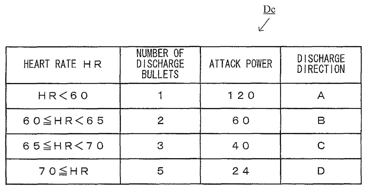
The discharge bullet setting table data Dc is previously set table data so as to set the number of bullets B to be discharged by a player character PC, the attack power of each bullet B, and the discharge direction. With reference toFIG. 14, an example of the discharge bullet setting table data Dc will be described below.
InFIG. 14, the “number of bullets to be discharged”, the “attack power”, and the “discharge direction”, which are set in accordance with the heart rate HR of a player, are described in the discharge bullet setting table data Dc. Here, the “number of bullets to be discharged” indicates the number of bullets B to be discharged at one pulse timing from the player character PC. The “attack power” indicates the attack power of one bullet B to be discharged from the player character PC against the enemy characters EC. The “discharge direction” indicates the direction in which at least one bullet B is discharged from the player character PC in accordance with the “number of bullets to be discharged” (e.g., the above-described discharge directions A to D).
Specifically, when the heart rate HR is lower than 60, the “number of bullets to be discharged” is set as one, the “attack power” is set as 120, and the “discharge direction” is set to A. That is, when the heart rate HR of the player is lower than 60, the player character PC discharges, at one pulse timing, one bullet B having an attack power120against the enemy characters EC in a discharge direction A. When the heart rate HR is equal to or higher than 60 and is lower than 65, the “number of bullets” is set as two, the “attack power” is set as 60, and the “discharge direction” is set to B. That is, when the heart rate HR of the player is equal to or higher than 60 and is lower than 65, the player character PC discharges, at one pulse timing, two bullets B each having an attack power60against the enemy characters EC in the discharge direction B. Further, when the heart rate HR is equal to or higher than 65 and is lower than 70, the “number of bullets to be discharged” is set as three, the “attack power” is set as 40, and the “discharge direction” is set to C. That is, when the heart rate HR of the player is equal to or higher than 65 and is lower than 70, the player character PC discharges, at one pulse timing, three bullets B each having an attack power40against the enemy characters EC in the discharge direction C. Further, when the heart rate HR is equal to or higher than 70, the “number of bullets to be discharged” is set as five, the “attack power” is set as 24, and the “discharge direction” is set to D. That is, when the heart rate HR of the player is equal to or higher than 70, the player character PC discharges, at one pulse timing, five bullets B each having an attack power24against the enemy character EC in the discharge direction D.
Note that, in the above example of setting of the discharge bullet setting table data Dc, regardless of the value of the heart rate HR of the player, the sum of the attack power of bullets discharged per pulse timing is set to 120. However, another manner of setting may be applicable. For example, the discharge bullet setting table data Dc may be set such that the attack power per pulse timing may be changed in accordance with the heart rate HR of the player. Alternatively, the data may be set such that either of the “number of bullets to be discharged” and the “attack power” may be changed in accordance with the heart rate HR of the player. Still alternatively, at least two of the “discharge directions” described in the discharge bullet setting table data Dc may be set to be a common discharge direction.
The player character position data Dd indicates a position of a player character PC in a virtual game world. The enemy character position data De indicates positions of enemy characters EC in the virtual game world. The bullet object position data Df indicates positions of bullets B in the virtual game world.
The image data Dg includes player character image data Dg1, enemy character image data Dg2, bullet object image data Dg3, and the like. The player character image data Dg1is data for arranging the player character PC in the virtual game world thereby to generate a game image. The enemy character image data Dg2is data for arranging the enemy characters EC in the virtual game world thereby to generate a game image. The bullet object image data Dg3is data for arranging the respective bullets B in the virtual game world thereby to generate a game image.
Next, the game processing performed on the game apparatus body5will be described in detail with reference toFIG. 15. Note thatFIG. 15is a flowchart showing an example of the game processing performed on the game apparatus body5. Note that, in the flowchart shown inFIG. 15, of the game processing, a process using the biological information from the vital sensor76and key data from the core unit70will be mainly described, and other game processes which do not directly relate to the present invention will not be described in detail. InFIG. 15, each step executed by the CPU10is abbreviated to “S”.
When the game apparatus body5is powered on, the CPU10of the game apparatus body5executes a boot program stored in the ROM/RTC13, thereby initializing each unit such as the main memory or the like. Thereafter, a game program stored in the optical disc4is loaded into the main memory, and the CPU10starts execution of the game program. The flowchart shown inFIG. 15indicates game processing which is performed after completion of the aforementioned process.
InFIG. 15, the CPU10performs an initial setting of the game processing (step41), and proceeds to the subsequent step. For example, in the initial setting of the game processing in step41, the CPU10performs initial settings of the virtual game world, the player character PC, the enemy characters EC, and the like. Further, in the initial setting of the game processing in step41, the CPU10initializes respective parameters used in the game processing thereafter.
Next, the CPU10obtains data indicating operation information from the core unit70(step42), and proceeds to the subsequent step. For example, the CPU10obtains operation information received from the core unit70, and updates the key data Da1using details of operations performed on the operation section72, the details being indicated by the latest key data included in the operation information. Further, the CPU10updates the pulse wave data Da2using a pulse wave signal indicated by the latest biological information data included in the operation information received from the core unit70.
Next, the CPU10moves the player character PC in the virtual game world in accordance with the details of operations performed on the operation section72, the details being indicated by the key data Da1(step43), and proceeds to the subsequent step. For example, when the key data Da1indicates that the left direction of the cross key72ahas been pressed, the CPU10moves the player character PC to the left in the virtual game world by a predetermined distance. Specifically, the CPU10moves the position of the player character PC indicated by the player character position data Dd to the left in the virtual game world by a predetermined distance, and updates the player character position data Dd using the moved position of the player character PC. Further, when the key data Da1indicates that the right direction of the cross key72ahas been pressed, the CPU10moves the player character PC to the right in the virtual game world by a predetermined distance. Specifically, the CPU10moves the position of the player character PC indicated by the player character position data Dd to the right in the virtual game world by a predetermined distance, and updates the player character position data Dd using the moved position of the player character PC.
Next, the CPU10determines whether or not the current moment is the pulse timing (step44). When the current moment is the pulse timing, the CPU10proceeds to subsequent step45. On the other hand, when the current moment is not the pulse timing, the CPU10proceeds to subsequent step48. For example, in above step44, the CPU10detects a predetermined shape feature point in a pulse wave when referring to a pulse wave signal indicated by the pulse wave data Da2, and determines that the current moment is the pulse timing at which the current moment corresponds to the shape feature point. For example, as the shape feature point, any one point may be selected from among: a point at which the pulse wave represents a local minimum value; a point at which the pulse wave represents a local maximum value; a point at which the contraction rate of the blood vessels represents a maximum value; a point at which the expansion rate of the blood vessels represents a maximum value; a point at which the acceleration of the blood vessel expansion rate represents a maximum value; a point at which the deceleration of the blood vessel expansion rate represents a maximum value; and the like. Any point may be the shape feature point to be determined as the pulse timing.
In step45, the CPU10calculates the heart rate HR of the player, updates the heartbeat data Db, and proceeds to the subsequent step. For example, the CPU10refers to the pulse wave signal based on the pulse wave data Da2, and calculates, as the interval of heartbeats at the current moment, a time interval between a pulse timing currently detected in step44and the immediately preceding pulse timing (e.g., the R-R interval; seeFIG. 9). The CPU10then calculates the heart rate HR by dividing 60 seconds by the interval of heartbeats, and updates the heart rate data Db using the newly calculated heart rate HR. Note that when the pulse timing is detected for the first time in the current process, the CPU10updates the heart rate data Db using the heart rate HR as a predetermined constant (e.g., 0), for example.
Next, the CPU10sets the number of bullets to be discharged and the attack power in accordance with the heart rate HR calculated in above step45(step46). For example, the CPU10refers to the discharge bullet setting table data Dc, and extracts a value of the “number of bullets to be discharged” and a value of the “attack power” which correspond to the heart rate HR calculated in step45. The CPU10sets the extracted value of the “number of bullets to be discharged” as the number of bullets B to be discharged at one pulse timing. The CPU10also sets the extracted value of the “attack power” as the attack power of each of the bullets B to be discharged.
Next, the CPU10performs a process to discharge, from the player character PC, the bullet B set in step46in a set discharge direction (step47), and then proceeds to the subsequent step. For example, the CPU10causes the bullet B, the number of which and the attack power of each of which are set in step46, to appear in the virtual game world, and performs a process of discharging the bullet B in its corresponding discharge direction, the discharge direction being described in the discharge bullet setting table data Dc. Specifically, in above step47, the CPU10causes the bullet to appear at a position of the bullet to be discharged (e.g., the frontmost position of the player character PC, when the player character PC is arranged in the position of the player character PC), the position of the bullets being determined based on the position of the player character PC indicated by the player character position data Dd. The CPU10then moves the bullet B from the position of the bullet to be discharged in their corresponding discharge direction.
In step48, based on a predetermined motion standard, the CPU10controls the motion of an other object in the virtual game world, and proceeds to the subsequent step. For example, the CPU10causes the enemy characters EC arranged in the virtual game world to move in a predetermined direction by a predetermined moving distance, causes a new enemy character EC to appear in the virtual game world, or causes an enemy character EC to disappear from the virtual game world when the enemy character EC is hit by a bullet B, thereby updating the enemy character position data De in accordance with respective situations. In addition, the CPU10moves a bullet B having been discharged in the virtual game world by a predetermined moving distance so as to proceed in the “discharge direction”, or causes the bullet B to disappear from the virtual game world when the bullet B has hit the enemy character EC, for example, thereby updating the bullet object position data Df.
Next, the CPU10performs a process of displaying on the monitor2the virtual game world having the player character PC, the enemy characters EC, the bullet B, and the like arranged therein (step49), and proceeds to the subsequent step. For example, the CPU10arranges the player character PC, the enemy characters EC, the bullet B, and the like in the virtual game world by using the player character position data Dd, the enemy character position data De, the bullet object position data Df, and the image data Dg. The CPU10then performs a process of displaying on the monitor2a predetermined range of the virtual game world.
Next, the CPU10determines whether or not to end the game (step50). For example, when the condition to be game over is satisfied, or when the player performs an operation to end the game, the game is to be ended. When the game is not to be ended, the CPU10returns to step42to repeat the processes, whereas when the game is to be ended, the CPU10ends the processes in the flowchart.
In this manner, according to the above-described game processing, the bullet B is discharged from the player character PC in accordance with the pulse timing of the player, and thus, a highly entertaining shooting operation that the player cannot easily anticipate can be realized. In addition, the number of bullets B and/or the attack power of each bullet B discharged per pulse timing of the player may be changed based on the heart rate HR of the player, that is, the interval of the pulse timings (interval of heartbeats) of the player, and thus in this case, a further highly entertaining shooting operation that the player cannot easily anticipate can be realized. Further, the discharge direction in which the bullet B is discharged from the player character PC may be also changed based on the interval of the pulse timings (interval of heartbeats) of the player, and thus, in this case as well, a further highly entertaining shooting operation that the player cannot easily anticipate can be realized.
In the above game processing, an example has been described where at least one selected from among: the number of bullets B to be discharged per pulse timing of the player; the attack power of each bullet B; and the discharge direction is changed in accordance with the heart rate HR of the player. However, the change may be made in accordance with other biological information based on the interval of the pulse timings (interval of heartbeats) of the player. For one example, in accordance with the biological information obtained by multiplying the heart rate HR of the player by the amplitude PA of the pulse wave (seeFIG. 9), at least one selected from among the number of bullets B to be discharged per pulse timing of the player, the attack power of each bullet B, and the discharge direction may be changed. For another example, in accordance with the pulse wave area PWA obtained from the pulse wave signal of the player (seeFIG. 9), at least one selected from among: the number of the bullets B to be discharged per pulse timing of the player; the attack power of each bullet B; and the discharge direction may be changed. In any example, the change is made based on the biological information which is obtained by associating the interval of the pulse timings (interval of heartbeats) of the player with the pulse wave amplitude PA. Thus, the above change may be set variously, and in addition, a game in which the mental state (e.g., difficulties and easiness) of a player affects the change can be realized.
Further, the number of bullets B to be discharged per pulse timing of the player, the attack power of each bullet B, and the discharge direction may be changed depending on various pieces of biological information. For example, the number of bullets B to be discharged per pulse timing of the player and the discharge direction are changed in accordance with any one item selected from among the heart rate HR, the heart rate HR×the pulse wave amplitude P, and the pulse wave area PWA, whereas the attack power of each bullet B is changed in accordance with an other item selected from among the heart rate HR, the heart rate HR×the pulse wave amplitude P, and the pulse wave area PWA. Accordingly, the number of the bullets B to be discharged per pulse timing of the player, the attack power of each bullet B, and the discharge direction are changed in a various manner.
Further, in the above-described example of the discharge bullet setting table data Dc, the number of bullets to be discharged is increased and the attack power of each bullet decreases as the heart rate HR rises. However, the number of bullets B to be discharged and the attack power of each bullet B may be set in a different manner. For example, in the discharge bullet setting table data Dc, the number of bullet to be discharged and the attack power may be set such that the number of bullets to be discharged decreases and the attack power of each bullet increases as the heart rate HR rises. Further, the number of bullets to be discharged and the attack power of each bullet B may be randomly set to correspond to any rise and/or fall range of the heart rate HR.
Further, in the above description referring toFIG. 10toFIG. 12, a shooting game has been introduced where a player character PC and enemy characters EC are arranged in the two-dimensional virtual game world and the player character PC discharges a bullet B to hit the enemy characters EC. The present invention is also applicable to a game of another type. For example, the present invention is applicable to a shooting game where an enemy character EC is arranged in a three-dimensional virtual game world and a player character PC discharges a bullet to hit the enemy character EC. In this case, the present invention may be applicable to a game generated based on a first-person point of view, that is, the point of view of the player character PC. For example, as shown inFIG. 16, on the monitor2, the enemy characters EC arranged in a three-dimensional virtual game space are displayed based on the point of view of the player character PC, and a shooting aim S of the player character PC is also displayed. At the pulse timing of the player, a bullet B is discharged while the direction indicated by the shooting aim S is set as the reference. In this case, the player moves the position of the shooting aim S by pressing any of the front, rear, left, and right directions of the cross key72aprovided on the core unit70, and causes the player character PC to stay at a fixed position in the virtual game space, or to automatically move in the virtual game space in accordance with a predetermined moving reference.
Further, in the above-described example of the game, the player moves the player character PC or the shooting aim S by operating the operation section72of the core unit70. Alternatively, it may be possible for the player to move the player character PC or the shooting aim S by using data outputted from the sensor fixedly provided in the core unit70. For example, it may be possible to provide the core unit70with: a sensor (the acceleration sensor701or a tilt sensor) which outputs data corresponding to the tilt of the core unit70relative to the direction of gravity (hereinafter simply referred to as a “tilt”); a sensor (magnetic sensor) which outputs data corresponding to an orientation of the core unit70; a sensor (gyro-sensor) which outputs data corresponding to rotational motion of the core unit70; and the like, whereby the data outputted from the sensor is used. In this case, the player character PC or the shooting aim S may be moved in accordance with the motion or tilt of the core unit70which is identifiable by using the above-described data. Further, a camera fixed to the core unit70(e.g., the imaging information calculation section74) may be used as the sensor. In this case, since an image taken by the camera changes depending on the position pointed to by the core unit70, analysis of this image enables calculation of the position pointed to by the core unit70, and thus it is possible to move the player character PC or the shooting aim S to the pointed to position.
Further, some of the above sensors may be arranged independently outside the core unit70. As an example, the whole of the core unit70is taken by a camera functioning as the sensor from outside the core unit70, and the image of the core unit70captured in the taken image is analyzed, whereby the motion, tilt, pointing-to position of the core unit70can be identified. Alternatively, a system may be used in which a unit fixed to the core unit70is used in combination with a unit arranged independently outside the core unit70. As an example of this case, a light emitting unit is arranged independently outside the core unit70, and the light emitted from the light emitting unit is taken by using a camera fixed to the core unit70. The image taken by the camera is analyzed, whereby the motion, tilt, and pointing-to position of the core unit70are identified. Further alternatively, a system may be used in which a magnetic field generation device is arranged independently outside the core unit70, and a magnetic sensor is fixedly mounted in the core unit70.
Further, when the sensor may be arranged independently outside the core unit70, it is not necessary to use the core unit70. For example, a player is taken by a camera functioning as the sensor, and the image of the player captured in the taken image is analyzed, whereby the motion or the posture of the player is identified, and the player character PC or the shooting aim S is moved in accordance with the identification result. Alternatively, a sensor provided to an input device, which is operated by a player stepping thereon (e.g., a board type controller), is used, the sensor detecting weight applied on the input device or any object placed on the input device, so that the motion or posture of the player operating the input device is identified, whereby the player character PC or the shooting aim S is moved in accordance with the identification result. When any of the sensors of the above-described types is used to move the player character PC or the shooting aim S, the core unit70need not be used.
Further, in the description above, a site of the player's body (e.g., a finger tip) is irradiated with infrared light, and a biological signal (pulse wave signal) of the player is obtained based on the amount of infrared light which is transmitted and received through the site of the body. That is, a change in volume of blood vessels is detected based on a so-called optical method thereby to obtain a volume pulse wave. Alternatively, in the present invention, the biological signal of the player may be obtained by using sensors of other types which obtain physiological information which occurs when the player performs physical activities. For example, the biological signal of the player may be obtained by detecting a change in pressure in blood vessels due to pulsation of the arterial system thereby to obtain a pressure pulse wave (e.g., a piezoelectric method). Alternatively, a muscle potential or a heart potential of the player may be obtained as the biological information of the player. The muscle potential or the heart potential can be detected by a commonly used method employing electrodes. For example, based on a minute change in current in the player's body, the biological signal of the player can be obtained. Alternatively, a blood flow of the player may be obtained as the biological information of the player. The blood flow is measured as a pulsating blood flow per heartbeat by using an electromagnetic method, an ultrasound method, or the like, whereby the pulsating blood flow is obtained as the biological signal of the player. A vital sensor may be attached to a site (e.g., a chest, an arm, an ear lobe, etc.) other than a finger portion of the player so as to obtain various biological signals described above. Strictly speaking, there may be a difference between the pulse and the heartbeat depending on the obtained biological signal. However, a heart rate and a pulse rate are considered to be substantially equal to each other, and therefore, the obtained biological signal can be processed in a manner similar to that of the aforementioned process. Accordingly, the game apparatus body5, which detects the pulse timing of a player by using peaks and dips of the pulse wave indicated by the pulse wave data obtained from the vital sensor76, actually detects the heartbeat or pulse of the player wearing the vital sensor76, and thus, the pulse timing can be used as the heartbeat or the pulse in a similar manner.
Further, in the description above, the vital sensor76transmits data indicating a pulse wave signal the game apparatus body5, in which various parameters are calculated from the pulse wave signal. Alternatively, data in other process steps may be transmitted to the game apparatus body5. For example, the vital sensor76may calculate any of parameters indicating: detection of the pulse timing; the interval of pulse timings (interval of heartbeats); the heart rate HR; the pulse wave amplitude PA; and the pulse wave area PWA, and transmit data indicating the parameters to the game apparatus body5. Alternatively, data halfway through calculation of the parameters from the pulse wave signal may be transmitted from the vital sensor76to the game apparatus body5.
Further, in the description above, the game processing is performed by using the controller7(vital sensor76, core unit70) and the game apparatus body5(i.e., the game apparatus3). Alternatively, at least some of process steps in the above game processing may be performed by using an other apparatus. For example, when the game apparatus3is configured to be communicable with an other apparatus (e.g., a server), process steps in the game processing may be performed by using the game apparatus3and the other apparatus in a combined manner. For example, when a virtual game world is set by the other apparatus, a case may be considered where: a pulse wave signal outputted from the vital sensor76and key data outputted from the core unit70is transmitted to the other apparatus; the game processing thereafter is performed on the other apparatus; and then a display process is performed on the game apparatus3. For another example, when a virtual game world is set by the other apparatus, a case may be considered where: data halfway through the game processing (e.g., data indicating the interval of pulse timings (such as the heart rate HR), position data of a player character PC or a shooting aim S, and data relating to a discharged bullet B) is transmitted from the game apparatus3to the other apparatus; the process using the transmitted data is performed on the other apparatus; and then a display process is performed on the game apparatus3. In this manner, by performing at least some of the process steps in the game processing on the other apparatus, a game processing similar to that described above can be realized. In addition, the present invention can be applied to game processing which allows a plurality of players playing with individual game apparatuses to join a virtual game world realized on the other apparatus (e.g., an on-line game which is operated on the other apparatus and is joined and shared by a plurality of players playing with the individual game apparatuses).
Note that, in this specification, the terms “game system” and “computer system” include: a system such as the game system1which comprises the game apparatus3including the optical disc4, the game apparatus body5, and the controller7, and the monitor2; and a computer system of a standalone type; and further includes a portable system which is realized by including these functions in one apparatus. Further, in this specification, the terms “game system” and “computer system” include: a system in which a plurality of game apparatuses are communicably connected to each other in a wired or wireless manner; and a system in which at least one game apparatus and an other apparatus (e.g., a server) are communicably connected to each other in a wired or wireless manner. Further, in this specification, the terms “game system” and “computer system” include, for example, a system that is configured with one apparatus such as the above game apparatus body5or the like, and also includes a so-called computer system that is configured with one apparatus which includes a CPU, a main storage unit, and the like.
Further, in the examples above, the present invention is applied to the stationary game apparatus3. The present invention is also applicable to any apparatus that includes at least a vital sensor, an input device to which operations by the player is inputted, and an information processing device for executing a process depending on information obtained from the sensor and the device. For example the present invention is applicable to a commonly used personal computer, a mobile phone, a Personal Digital Assistant (PDA), a hand-held game apparatus, and the like.
Further, in the description above, the core unit70and the game apparatus body5are connected by wireless communication. Alternatively, the core unit70and the game apparatus body5may be electrically connected via a cable. In this case, a cable connected to the core unit70is connected to a connection terminal of the game apparatus body5.
Further, of the core unit70and the vital sensor76constituting the controller7, only the core unit70is provided with the communication section75. Alternatively, the vital sensor76may be provided with the communication section which wirelessly transmits biological information data to the game apparatus body5. Alternatively, each of the core unit70and the vital sensor76may be provided with the communication section. For example, the communication sections provided in the core unit70and the vital sensor76may each wirelessly transmit biological information data or operation data to the game apparatus body5. Alternatively, the communication section of the vital sensor76may wirelessly transmit biological information data to the core unit70, and the communication section75of the core unit70may receive it. And thereafter, the communication section75of the core unit70may wirelessly transmit, to the game apparatus body5, operation data of the core unit70along with the biological information data of the vital sensor76. In these cases, the connection cable79for electrically connecting the core unit70and the vital sensor76is no longer required.
Further, the shape of the core unit70, and the shape, number, and arrangement or the like of the operation section72arranged thereon, which are described above, are merely examples. Even in the case of other shapes, numbers, arrangements, and the like, the present invention can be achieved. Further, the shape of the vital sensor76, and the types, numbers, arrangements, and the like of the components provided therein, which are described above, are also merely examples. Even in the case of other types, numbers, arrangements, and the like, the present invention can be achieved. Further, the coefficients, criteria, expressions, processing orders, and the like used in the above-described processes are also merely examples. Even in the case of other values, expressions, processing orders, the present invention can be achieved.
Further, the above-described game program may be supplied to the game apparatus body5not only from an external storage medium, such as the optical disc4or the like, but also via a wireless or wired communication line. Further, the game program may be previously stored in a non-volatile storage device of the game apparatus body5. Examples of the information storage medium having the game program stored therein include a flexible disk, a hard disk, a magnetic optical disk, a magnetic tape, and a non-volatile memory in addition to a CD-ROM, a DVD, and any other optical disc-shaped storage medium similar to those. Further, as the information storage medium storing therein the game program, a volatile memory which stores the game program temporarily may be used.
While the present invention has been described in detail, the foregoing description is in all aspects illustrative and not restrictive. It is understood that numerous other modifications and variations can be devised without departing from the scope of the invention. It is should be understood that the scope of the present invention is interpreted only by the scope of the claims. It is also understood that, from the description of specific embodiments of the present invention, the one skilled in the art can easily implement the present invention in the equivalent range based on the description of the present invention and on the common technological knowledge. Further, throughout the specification, it is understood that terms in singular form should include a concept of plurality. Thus, it should be understood that articles or adjectives indicating the singular form (e.g., “a”, “an”, “the”, and the like in English) includes the concept of plurality unless otherwise specified. Further it should be understood that terms used in the present specification have meanings generally used in the art concerned unless otherwise specified. Therefore, unless otherwise defined, all the jargons and technical terms have the same meanings as those generally understood by one skilled in the art of the present invention. In the event of any confliction, the present specification (including meanings defined herein) has priority.
A storage medium having a game program stored therein, a game apparatus, a control method, and a game system according to the present invention can realize a highly entertaining operation which the player cannot easily anticipate, and are useful as a game program, a game apparatus, a control method, a game system, and the like which enables game progress using biological information of a player.
Claims
- A non-transitory computer readable storage medium having stored therein a game program executed by a computer of a game apparatus performing game processing to cause a player object to perform in a virtual game world in accordance with information corresponding to a biological signal acquired from a player, the game program causing the computer to execute instructions comprising: acquiring the biological signal from the player corresponding to a blood pulse related to contractions of a heart of the player;detecting the blood pulse or heartbeat of the player in accordance with the acquired biological signal;calculating, based on the acquired biological signal, an interval of detection of the blood pulse or the heartbeat of the player;and causing the player object to perform a motion of discharging at least one discharge object, from a plurality of types of discharge objects, in the virtual game world when the pulse or the heartbeat is detected, the plurality of types of discharge objects having different configurations defined for the at least one discharge object, and a configuration of one of the plurality of types of discharge objects being discharged is changed in accordance with the calculated interval of detection.
- The non-transitory computer readable storage medium having stored therein the game program according to claim 1 , the game program further causing the computer to execute instructions comprising: causing a target object, which is a target to be hit by a discharge object, to appear in the virtual game world, wherein when one of the at least one discharge object has hit the target object, an effect of the one of the at least one discharge object exerted on the target object is changed in accordance with the calculated interval of detection.
- The non-transitory computer readable storage medium having stored therein the game program according to claim 1 , wherein a number of the at least one discharge object to be discharged when the player object performs one discharging motion is changed in accordance with the calculated interval of detection.
- The non-transitory computer readable storage medium having stored therein the game program according to claim 3 , the game program further causing the computer to execute instructions comprising: causing a target object, which is a target to be hit by the at least one discharge object, to appear in the virtual game world, wherein when one of the at least one discharge object has hit the target object, an effect of the one of the at least one discharge object exerted on the target object is changed in accordance with the calculated interval of detection.
- The non-transitory computer readable storage medium having stored therein the game program according to claim 4 , wherein when one of the at least one discharge object has hit the target object, the higher a number of the at least one discharge object discharged, the lower an effect of the one of the at least one discharge object exerted on the target object.
- The non-transitory computer readable storage medium having stored therein the game program according to claim 3 , wherein a direction in which the at least one discharge object is to be discharged when the player object performs one discharging motion corresponds to the number of objects of the at least one discharge object discharged in one discharging motion.
- The non-transitory computer readable storage medium having stored therein the game program according to claim 2 , wherein when one of the at least one discharge object has hit the target object, the effect of the one of the at least one discharge object exerted on the target object corresponds to a size of the calculated interval of detection.
- The non-transitory computer readable storage medium having stored therein the game program according to claim 1 , wherein a first parameter and a second parameter which relate to the at least one discharge object are set in accordance with the calculated interval of detection.
- The non-transitory computer readable storage medium having stored therein the game program according to claim 8 , wherein when the calculated interval of detection increases, the first parameter decreases in value while the second parameter increases in value, whereas when the calculated interval of detection decreases, the first parameter increases in value while the second parameter decreases in value.
- The non-transitory computer readable storage medium having stored therein the game program according to claim 1 , the game program further causing the computer to execute instructions comprising: acquiring an operation input performed by the player on an input device, wherein the player object performs in accordance with the acquired operation input.
- The non-transitory computer readable storage medium having stored therein the game program according to claim 1 , the game program further causing the computer to execute instructions comprising: acquiring an operation input performed by the player on an input device, wherein a direction in which the at least one discharge object is to be discharged from the player object corresponds to the acquired operation input.
- The non-transitory computer readable storage medium having stored therein the game program according to claim 1 , wherein the biological signal is acquired as a signal relating to a blood pulse wave or the heartbeat of the player, and the pulse or the heartbeat of the player is detected as a timing at which the signal relating to the acquired pulse wave or the heartbeat indicates a local minimum value or a local maximum value.
- The non-transitory computer readable storage medium having stored therein the game program according to claim 1 , wherein the biological signal is acquired as a signal relating to a blood pulse wave or the heartbeat of the player, and the pulse or the heartbeat of the player is detected as a timing at which a contraction rate or an expansion rate of blood vessels reaches a maximum value in the signal relating to the acquired pulse wave or the acquired heartbeat.
- The non-transitory computer readable storage medium having stored therein the game program according to claim 1 , wherein the biological signal is acquired as a signal relating to a blood pulse wave or the heartbeat of the player, and the pulse or the heartbeat of the player is detected as a timing at which contraction acceleration or expansion acceleration of blood vessels reaches a maximum value in the signal relating to the acquired pulse wave or the acquired heartbeat.
- A game apparatus performing game processing to cause a player object to perform in a virtual game world in accordance with information corresponding to a biological signal acquired from a player, the apparatus comprising: a biological signal acquisition unit for acquiring the biological signal from the player corresponding to a blood pulse related to contractions of a heart of the player;a pulse detection unit for detecting the blood pulse or heartbeat of the player in accordance with the biological signal acquired by the biological signal acquisition unit;an interval of detection unit for calculating, based on the acquired biological signal, an interval of detection of the blood pulse or the heartbeat of the player;and a player object motion control unit for causing the player object to perform a motion of discharging at least one discharge object, from a plurality of types of discharge objects, in the virtual game world when the pulse detection unit detects the pulse or the heartbeat, the plurality of types of discharge objects having different configurations defined for the at least one discharge object, and a configuration of one of the plurality of types of discharge objects being discharged is changed in accordance with the calculated interval of detection.
- A control method in an information processing system including at least one information processing device, the method comprising: acquiring a biological signal from a user corresponding to a blood pulse related to contractions of a heart of the user;detecting the blood pulse or heartbeat of the user in accordance with the biological signal;calculating, based on the acquired biological signal, an interval of detection of the blood pulse or the heartbeat of the player;and causing a user object to perform a motion of discharging at least one discharge object, from a plurality of types of discharge objects, in the virtual game world when the pulse or the heartbeat is detected, the plurality of types of discharge objects having different configurations defined for the at least one discharge object, and a configuration of one of the plurality of types of discharge objects being discharged is changed in accordance with the calculated interval of detection.
- A game system which includes a plurality devices communicably connected to each other, and performs game processing to cause a player object to perform a motion in a virtual game world in accordance with information corresponding to a biological signal acquired from a player, the system comprising: a biological signal acquisition unit for acquiring a biological signal from the player corresponding to a blood pulse related to contractions of a heart of the player;a pulse detection unit for detecting the blood pulse or heartbeat of the player in accordance with the biological signal acquired by the biological signal acquisition unit;an interval of detection unit for calculating, based on the acquired biological signal, an interval of detection of the blood pulse or the heartbeat of the player;and a player object motion control unit for causing the player object to perform a motion of discharging at least one discharge object, from a plurality of types of discharge objects, in the virtual game world when the pulse detection unit detects the pulse or the heartbeat, the plurality of types of discharge objects having different configurations defined for the at least one discharge object, and a configuration of one of the plurality of types of discharge objects being discharged is changed in accordance with the calculated interval of detection.
- The non-transitory computer readable storage medium having stored therein the game program according to claim 1 , wherein the blood pulse corresponds to a throbbing of arteries in the player produced by contractions of the heart of the player as palpated, discerned, or detected at a specific body site.
- The non-transitory computer readable storage medium having stored therein the game program according to claim 1 , wherein a number, a movement direction, and a damage amount of the at least one discharge object correspond to the calculated interval of detection of the pulse or the heartbeat of the player.
- A non-transitory computer readable storage medium having stored therein a program, executed by an information processing device, for causing a player object to perform in a virtual game world in accordance with information corresponding to a biological signal acquired from a player, the game program causing the computer to perform functionality comprising: detecting a blood pulse or a heartbeat of a player based on an acquired biological signal of the player;calculating an interval of detection of the blood pulse or the heartbeat of the player based on the acquired biological signal;discharging, from the player character in the virtual game world, one or more discharge objects based on the detected pulse or heartbeat;and varying an amount, a direction, and a performance type of the one or more discharge objects in accordance with the calculated interval of detection.
Disclaimer: Data collected from the USPTO and may be malformed, incomplete, and/or otherwise inaccurate.