U.S. Pat. No. 8,430,753
VIDEO GAME SYSTEM WITH WIRELESS MODULAR HANDHELD CONTROLLER
AssigneeNintendo Co., Ltd.
Issue DateMarch 24, 2011
Illustrative Figure
Abstract
A home entertainment system for video games and other applications includes a main unit and handheld controllers. The handheld controllers sense their own motion by detecting illumination emitted by emitters positioned at either side of a display. The controllers can be plugged into expansion units that customize the overall control interface for particular applications including but not limited to legacy video games.
Description
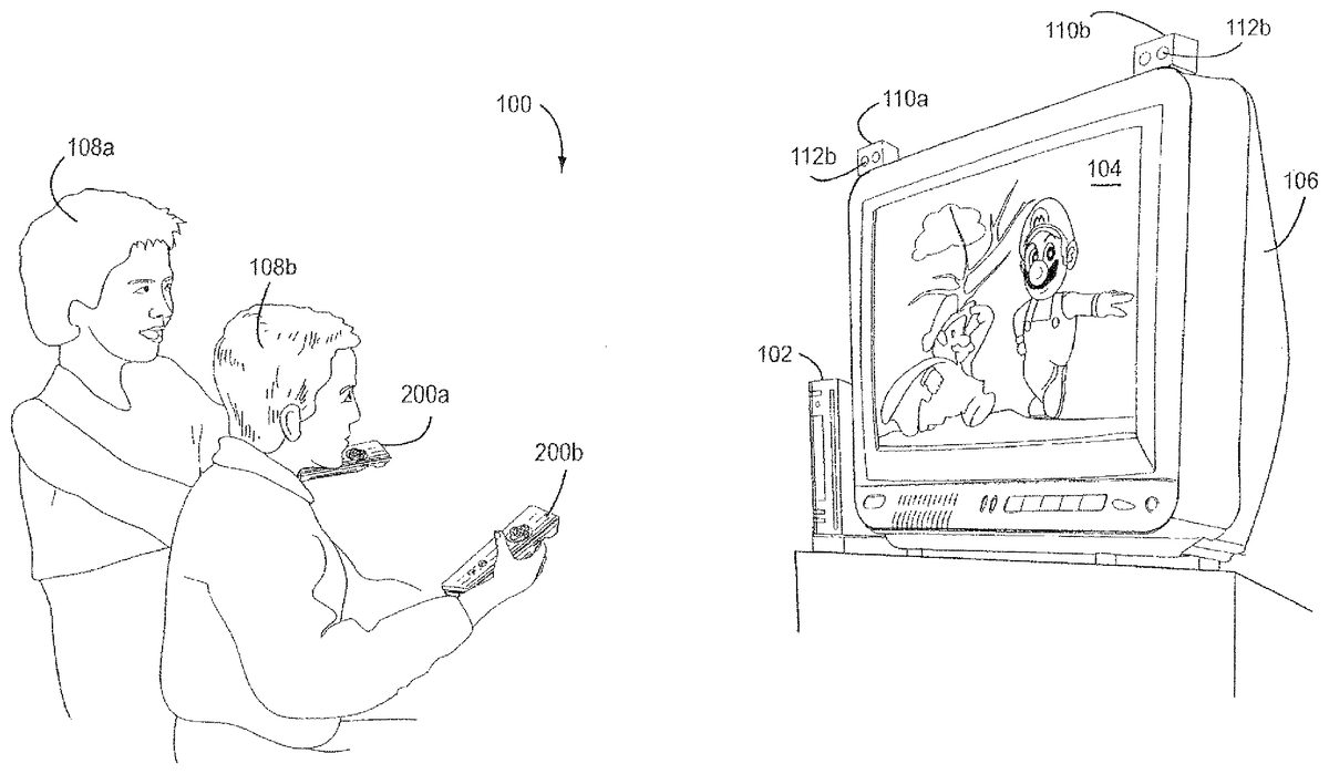
DETAILED DESCRIPTION Example Overall Exemplary Illustrative Non-Limiting System FIG. 1shows an illustrative, exemplary non-limiting implementation of a video game system100. System100includes a main unit102sometimes also called a “console.” Main unit102executes applications including video game software, and generates images for display on the display104of a conventional home color television set or other display device106. Main unit102also generates sound for reproduction by TV set106. People108can interact with the video game play to control or affect the images and the progression of the game or other application. Main unit102in the exemplary illustrative non-limiting implementation can be used to play a variety of different games including driving games, adventure games, flying games, fighting games, and almost any other type of game one might think of. The video game software that main unit102executes may be delivered on bulk storage devices such as optical disks, semiconductor memory devices or the like, it may be downloaded into the main unit over a network, or it may be provided to the main unit in any other desired manner. Main unit102may also be capable of performing applications in addition to video games (e.g., movie playback, email, web browsing, or any other application one can imagine). A security system built into main unit102may ensure that only authorized or authentic applications are executed. FIG. 1shows people (“video game players”)108a,108binteracting with main unit102to play a video game. While two players108are shown, any number of players may interact with the main unit102at any given time. In the exemplary illustrative non-limiting implementation shown, each video game player108holds and operates a wireless handheld control unit (“controller”)200. The players108operate these controllers200to generate input signals. The controllers200communicate their input signals wirelessly to main unit102. Such wireless communications can be by any convenient wireless method such as radio transmission, infrared, ultraviolet, ultrasonic or any other desired technique. Wireless ...
DETAILED DESCRIPTION
Example Overall Exemplary Illustrative Non-Limiting System
FIG. 1shows an illustrative, exemplary non-limiting implementation of a video game system100. System100includes a main unit102sometimes also called a “console.” Main unit102executes applications including video game software, and generates images for display on the display104of a conventional home color television set or other display device106. Main unit102also generates sound for reproduction by TV set106. People108can interact with the video game play to control or affect the images and the progression of the game or other application.
Main unit102in the exemplary illustrative non-limiting implementation can be used to play a variety of different games including driving games, adventure games, flying games, fighting games, and almost any other type of game one might think of. The video game software that main unit102executes may be delivered on bulk storage devices such as optical disks, semiconductor memory devices or the like, it may be downloaded into the main unit over a network, or it may be provided to the main unit in any other desired manner. Main unit102may also be capable of performing applications in addition to video games (e.g., movie playback, email, web browsing, or any other application one can imagine). A security system built into main unit102may ensure that only authorized or authentic applications are executed.
FIG. 1shows people (“video game players”)108a,108binteracting with main unit102to play a video game. While two players108are shown, any number of players may interact with the main unit102at any given time. In the exemplary illustrative non-limiting implementation shown, each video game player108holds and operates a wireless handheld control unit (“controller”)200. The players108operate these controllers200to generate input signals. The controllers200communicate their input signals wirelessly to main unit102. Such wireless communications can be by any convenient wireless method such as radio transmission, infrared, ultraviolet, ultrasonic or any other desired technique. Wireless peripherals could include Bluetooth, 802.11 (WiFi), HiperLAN/1, HiperLAN/2, HomeRF, VWB, WiMax or other. In other implementations, cords or cables could be used to connect controllers200to main unit102.
In the exemplary illustrative non-limiting implementation of system100shown, players108operate handheld controllers200in various ways to provide input signals to main unit102. For example, players108may depress buttons or otherwise manipulate other controls on controllers200to generate certain input signals. The effect of such control manipulations in the exemplary illustrative non-limiting implementation depends, at least in part, on the particular software that main unit102is executing. For example, depressing a certain button may provide a “start game” or “pause game” in some contexts, and may provide different functions (e.g., “jump character”) in other contexts.
In the illustrative exemplary non-limiting implementation shown, controllers200have internal capabilities for detecting position and/or orientation. In the exemplary illustrative non-limiting implementation, players may change the orientation or position of controllers200to generate input signals. Controllers200may sense position and/or orientation and report that information to main unit102. Main unit102may use that information to control or affect video game play or other functionality.
In one exemplary illustrative non-limiting implementation, each handhold controller200may include an internal position, attitude or orientation sensor that can sense the position, attitude and/or orientation of the controller relative to the earth's gravitational force. Such a sensor may for example comprise a 3-axis accelerometer that can sense orientation (or changes in orientation) of the controller200relative to the direction of earth's gravitational pull. The output of such a sensor may be reported to main unit102and used for example to control motion of a character displayed on display104.
In addition, the exemplary illustrative non-limiting implementation of system100shown inFIG. 1includes wireless emitters110a,110b. These wireless emitters110may be placed on each side of display104in alignment with the edges of the screen. The wireless emitters110may for example each comprise one or more light emitting diodes or other devices112that emit infrared or other electromagnetic or other radiation.
In one exemplary illustrative non-limiting implementation, the energy that emitters110emit has a wavelength or other characteristic that allows the radiation to be readily distinguished from ambient radiation. In the exemplary illustrative non-limiting implementation, handheld controllers200each detect the radiation emitted by emitters110and generate signals indicative of the controller's relative position and/or movement. Multiple controllers200can sense the same emitted radiation and generate different signals depending on the position or movement of that particular controller. Controllers200report the relative position and/or movement signal to main unit102. Main unit102may take any appropriate action in response to such signals such as, for example, moving, rotating or otherwise changing a game character or other object or background on the display104, scrolling a screen, selecting a different game function, or taking other actions.
In the exemplary illustrative implementation shown, the emitters110are added or retro-fitted onto a conventional color television set106by for example using an adhesive to attach the emitters onto the top housing of the television set on the extreme left and right of the housing in alignment with the edges of display104. In this exemplary illustrative non-limiting implementation, emitters110can be connected to main unit102by cables or wires run behind the television set106. In other implementations, emitters110could be built-in to television set106or mounted separately (e.g., on a set top box or otherwise). In still other implementations, emitters110could possibly be replaced with small reflective surfaces attached by adhesive to corners of display104, and controllers200could emit electromagnetic radiation and receive reflections from the reflective surfaces (e.g., whose angle of incidence is equal to angle of reflectance). In still other implementations, controllers200could emit electromagnetic radiations and units110could include sensors that sense the emitted radiation. Other implementations are possible.
Example Illustrative Non-Limiting Handheld Controller Design
FIG. 2shows a perspective view of an exemplary illustrative non-limiting implementation of controller200. Controller200provides a housing202that is graspable by one hand (seeFIGS. 2A,2B,2C). Controller200in the exemplary illustrative non-limiting implementation is compact and has a solid rugged feel to it. It can be dropped onto a hard surface without breaking. Portions of its housing202are curved to fit comfortably into the hand (seeFIGS. 2A,2B,2C).
As shown inFIG. 2A, the thumb can be positioned to operate controls on a top control surface204while the fingers are comfortably wrapped around the controller's bottom surface203. The digits of the hand (including the thumb) can operate the different controls arrayed on a top control surface204and elsewhere on the controller without fatigue and without wasted or undue motion. The controller200is small and lightweight enough to be comfortably held and supported for long periods of time without fatigue. Controller200is dimensioned to exactly and comfortably fit the average hand—not too small, not too big. The controls are arranged such that the controller200can be operated equally easily by the right hand or the left hand.
The controller housing202provides a top control surface204providing an array of controls depressible with the digits (fingers and/or thumbs) of the user's hand. In one illustrative non-limiting implementation, the user may operate a direction switch206with a thumb or forefinger to indicate a direction in two dimensions. In the illustrative non-limiting exemplary implementation shown, the directional switch206may comprise a switch surface208that can be rocked in different directions to provide different direction signals. The simplest form of such a directional switch206may comprise a so-called “cross switch” (a switch in the shape of a cross) that can be rocked in four different directions to provide four different, mutually exclusive direction signals (i.e., up, down, left, right). A somewhat more flexible form of a directional switch208may comprise a circular switch surface208that can be rocked in any of a number of different directions to provide corresponding different control signals indicating for example twelve, sixteen or more different directions. Other directional switch configurations could be used to provide a much higher number of directional inputs approaching, equaling or exceeding the number of signals from an analog or digital joystick. A touch or “joy” pad, a pointing stick, a trackball, or other input device could be used instead of or in addition to a switch. If a joypad were used, it could likely be operated in a direction-indicating mode as opposed to a “drag displacement” mode. Other arrangements could include touch sensitive display(s) or other types of displays.
Top control surface204in the exemplary illustrative non-limiting implementation also provides a pair of thumb-operated control switches210a,210b. These control switches210a,210bcan be oriented as shown, or they could each be rotated say 45 degrees so as to be angularly displayed from one another in order to expose more surface area to a thumb positioned to operate either control switches210or directional switch206. Control switches210a,210bcould be used to actuate a variety of game or other functions including for example “start” and “select” functions.
Top control surface204may also provide an additional push button214operated by the thumb for other functionality selection. A slide switch216on the side of housing202may be operated to provide on/off or other functionality. Depending on requirements, a slide switch216could be located on either or both side surfaces of the exemplary controller200.
Top control surface204in the exemplary illustrative non-limiting implementation further provides two additional controls212a,212bthat may comprise indicator lamps or lights. Alternatively, such controls212could comprise additional operable controls such as push button switches, so-called “pointing stick” type input devices, or other input devices. These controls212may be relatively dormant or little used (while not being subject to accidental operation) when the controller200is operated in the hand positions shown inFIGS. 2A,2B,2C,2D,2E,2F. However, another way of using controller200is to hold the controller in one hand (or place it on a flat surface such a table) and operate its controls with the forefinger and other fingers of the other hand. In such an alternate operating mode, the forefinger could be used to operate controls212a,212bif they are activatable input devices as opposed to indicators.FIG. 2Dfor example shows that in one exemplary illustrative implementation, the user may move his or her thumb forward or backward to access different controls.FIG. 2Dshows the ability to move the thumb side to side to provide different control actuations.FIG. 2Fshows an exemplary illustrative non-limiting implementation whereby the user can hold the handheld controller in both hands and operate it with both left thumb and right thumb simultaneously.
FIG. 3shows an exploded view of controller200with a top plate204removed to reveal a printed circuit board220. Metallic pathways (not shown) and associated solder or other electrical interconnections may be used to electrically interconnect components via PC board220. Various components including integrated circuit chips222(e.g., a wireless RF “Bluetooth” or other communications device, an accelerometer and other components) may be mounted to the printed circuit board220. The printed circuit board220may also serve as a mounting surface for the directional switch206, controls210,212, etc. The printed circuit board220in one exemplary illustrative non-limiting implementation provides a rugged fiberglass structure used to both mount and electrically interconnect components of controller200. The same or different printed circuit board220may provide an edge or other connector224for use in electrically connecting controller200to other devices (to be described below).FIG. 3Ashows a different exemplary illustrative non-limiting implementation with a different exemplary non-limiting control layout. Further configurations are also possible.
FIG. 4shows a bottom view of an exemplary illustrative non-limiting implementation of controller200. The bottom view reveals an access plate230for installing one or more small conventional removable/replaceable battery cells (seeFIG. 5).FIG. 4also shows an additional “trigger” type switch232operable by the forefinger when the controller is held in the hand (seeFIG. 2A,2C). “Trigger” switch232may for example sense pressure to provide a variable input signal that depends on how much pressure the user's forefinger is exerting on the switch. Such a variable-pressure “trigger” switch232can be used in a video game to fire weapons, control the speed of a vehicle in a driving or space game, or provide other functionality.
In the exemplary illustrative non-limiting exemplary implementation shown, the trigger switch232is disposed on an angular surface234of the bottom surface240of controller200within a V-shaped depression236located near the front distal end238. This V-shaped depression236is dimensioned to comfortably provide a resting and grasping slot for the forefinger (seeFIG. 2C) which may be slightly rotated and pulled toward the user between a resting position (seeFIG. 2C) and an actuation position (seeFIG. 2A). With the middle, ring and pinkie fingers wrapped around and grasping the curved center240cand rear240rportions of the controller's bottom surface203and the forefinger comfortably engaged within the v-shaped depression236, the user feels quite comfortable holding and operating controller200with one hand and positioning and aiming it precisely in desired directions.
FIG. 5shows an exploded view of controller200with the lower housing portion240removed to expose internal components such as removably replaceable batteries250and associated holders/contacts252, and trigger switch232. While two batteries250are shown inFIG. 5, any number of batteries (e.g., one, three, etc.) can be used depending on weight, power and other requirements. Note that to replace batteries250, the user would not usually remove the lower housing240but rather would simply remove the access plate230. In other configurations, the controller200might be rechargeable and batteries250could be of the nickel-cadmium or other type that do not require routine replacement. In such exemplary configuration, the controller200could be placed into a charging station to recharge the batteries250instead of expecting the user to replace the batteries. WhileFIG. 5shows a separate edge connector224, it is possible that the edge connector could be formed by a distal edge of the printed circuit board220.
FIGS. 6B-6Hshow an additional exemplary non-limiting illustrative implementation of a handheld controller with a different control configuration. A power button1002may be used to activate power on the main unit102. A control pad206provides directional input. An A button1004can be operated by the thumb instead of the control pad206to provide a momentary on-off control (e.g., to make a character jump, etc.). Select and start buttons1006,1008may be provided for example to start game play, select menu options, etc. A menu button1010(which may be recessed to avoid accidental depression) may be provided to display or select menu/home functions. X and Y buttons may be used to provide additional directional or other control. Light emitting diodes or other indicators1016a-dmay be used to indicate various states of operation (e.g., for example to designate which controller number in a multi-controller environment the current controller is assigned). A connector1018is provided to connect the controller to external devices.FIG. 6Cshows an underneath side perspective view,FIG. 6Dshows a top plan view,FIG. 6Eshows a side plan view,FIG. 6Fshows a bottom plan view,FIG. 6Gshows a front plan view, andFIG. 6Hshows a rear plan view.
Example Illustrative Non-Limiting Optical Pointing Device Motion Detection
FIG. 6shows a front perspective view of controller200illustrating an additional sensing component260also shown inFIG. 5. Sensor260in the exemplary illustrative non-limiting implementation is disposed on the “nose” or front surface262of controller200so that it points forward, looking down a pointing axis P. The direction of pointing axis P changes as the user changes the orientation of controller200. It is possible to provide a pivot mechanism (seeFIG. 6A) to allow the user to pivot the nose portion up and down to provide better ergonomics (e.g., the user could be sitting on the floor below the level of the emitters112and still be able to point directly forward, with the sensor260axis P being aimed upwardly).
Sensing component260in the exemplary illustrative non-limiting implementation comprises an infrared-sensitive CCD type image sensor. Sensor260may comprise a one-dimensional line sensor or it could comprise a 2D sensor such as for example a low resolution monochrome CCD or other camera. Motion tracking sensor260may include a lens and a closely coupled digital signal processor to process incoming images and reduce the amount of information that needs to be conveyed to main unit102. In one exemplary non-limiting implementation, motion tracking sensor260may include a 128 pixel by 96 pixel relatively low resolution monochrome camera, a digital signal processor and a focusing lens. More than one such sensor could be used if desired.
In the exemplary illustrative non-limiting implementation, sensor260gives controller200optical pointing capabilities. For example, movement of the controller200can be detected (e.g., by the controller itself) and used to control what is being displayed on display104. Such control could include for example scrolling of the screen, rotation or other reorientation of display objects in response to rotation/reorientation of controller200, and other responsive interactive displays. Such control may provide a better moment arm as compared to a joystick.
In the exemplary illustrative non-limiting implementation, sensor260is designed and configured to sense the emitters110shown inFIG. 1.FIGS. 7A,7B show that sensor260has a certain well defined field of view (FOV) symmetrical with the sensor pointing axis P. For example, the sensor260may have a field of view of about 20.5 degrees on each or every side of pointing axis P (this particular field of view angle is a design choice; other choices are possible in other configurations). Such well defined field of view provides an acute triangularly shaped (or cone-shaped for 2D sensor configurations) viewing area that sensor260can “see”—with the base of the triangle increasing in length as distance from the controller200increases. Sensor260also has a well defined sensitivity such that it can only “see” IR emissions above a certain range of intensity. Emitters112are designed in the exemplary illustrative non-limiting to provide sufficient output power and beam spreading consistent with the sensitivity of sensor260such that sensor can “see” the emitters at ranges consistent with how video game players arrange themselves in a room relative to a television set106(taking into account that a player may sometimes sit close to the television when playing by himself, that players may be sitting on the floor, standing, sitting on chairs or couches or other furniture, etc.).
In more detail,FIG. 7Ashows that in the exemplary illustrative non-limiting implementation, the overall field of view of sensor260is wider than the typical separation of emitters112and is also wider than beam width of each emitter112. In one exemplary illustrative non-limiting implementation, the ratio of the beam spreading angle (e.g., 34 degrees) of the beams emitted by emitters112to the field of view (e.g., 41 degrees) of sensor260may be approximately 0.82 (other ratios are possible). Plural emitters112can be used at each emission point to provide a wider beam (horizontal field of view) than might otherwise be available from only a single emitter, or a lens or other optics can be used to achieve desired beam width.
At an average distance from controller200to television set106and associated emitters112and assuming a maximum television screen size (and thus a maximum physical separation between the emitters), such a ratio may maximize the displacement of two radiation “dots” or points appearing on the CCD sensor array270that sensor260comprises. Referring toFIG. 7Afor example, when the central axis of sensor260is directed centrally between displaced emitters112(note that in one exemplary illustrative non-limiting implementation, the emitters are disposed on either side of the television display and are therefore relatively far apart relative to the resolution of the image being generated), the CCD array270that sensor260defines will register maximal illumination at two points near the ends of the sensor array. This provides a higher degree of resolution when the sensor260's central axis P is displaced relative to the center of separation of the emitters112(seeFIG. 7B) even when using a relatively low resolution CCD imaging array (e.g., a 128-cell long sensor array). Note that while a linear array270is illustrated inFIGS. 7A,7B for sake of convenience, a rectangular array could be used instead.
In the illustrative, exemplary non-limiting implementation shown, it is unnecessary to modulate or synchronize emitters112in the exemplary illustrative non-limiting implementation, although it may be desirable to power down the emitters when not in use to conserve power usage. In other arrangements, however, synchronous detection, modulation and other techniques could be used.
The exemplary illustrative non-limiting implementation of controller200and/or main unit102includes software or hardware functionality to determine the position of controller200relative to emitters112, in response to the illumination maxima sensed by sensor260. In one example illustrative non-limiting implementation, controller200includes an on-board processor coupled to the sensor260that interprets the currently detected illumination pattern, correlates it with previous sensed illumination patterns, and derives a current position. In another example illustrative non-limiting implementation, controller200may simply report the sensed pattern to main unit102which then performs the needed processing to detect motion of controller200. The sensor could be affixed to the human operating the system to provide additional control.
Since it may not be desirable to require end users of system100to measure and program in the precise distance between the emitters112and since television sets vary in dimension from small screens to very large screens, controller200does not attempt to calculate or derive exact positional or distance information. Rather, controller200may determine movement changes in relative position or distance by analyzing changes in the illumination pattern “seen” by CCD array270.
It may be possible to ask the user to initially point the controller200at the center of the television screen104and press a button, so as to establish a calibration point (e.g., see FIG.7A)—or the game player may be encouraged to point to the center of the screen by displaying an object at the center of the screen and asking the user to “aim” at the object and depress the trigger switch. Alternatively, to maximize user friendliness, the system can be self-calibrating or require no calibration at all.
Differences in the illumination pattern that CCD array270observes relative to previously sensed patterns (see e.g.,FIG. 7B) can be used to determine or estimate movement (change in position) relative to previous position in three dimensions. Even though the CCD array270illumination shown in theFIG. 7Bscenario is ambiguous (it could be obtained by aiming directly at emitter112aor at emitter112b), recording and analyzing illumination patterns on a relatively frequent periodic or other basis (e.g., 200 times per second) allows the controller to continually keep track of where it is relative to the emitters112and previous controller positions. The distance between the illumination points of emitters112and CCD array270can be used to estimate relative distance from the emitters. Generally, game players can be assumed to be standing directly in front of the television set and perpendicular to the plane of display106. However, scenarios in which controller200is aimed “off axis” such that its central axis P intersects the plane of emitters112at an angle other than perpendicular can also be detected by determining the decreased separation of the two maximum illumination points on the CCD array270relative to an earlier detected separation. Care must be taken however since changes in separation can be attributed to changed distance from the emitters112as opposed to off-axis. Simpler mathematics can be used for the motion and relative position detection if one assumes that the player is aiming the sensor axis P directly at the display104so the axis perpendicularly intersects the plane of the display.
Software algorithms of conventional design can ascertain position of controller200relative to emitters112and to each logical or actual edge of the display screen104. If desired, controller200may further include an internal conventional 3-axis accelerometer that detects the earth's gravitational forces in three dimensions and may thus be used as an inclinometer. Such inclination (orientation) information in three axis can be used to provide further inputs to the relative position-detecting algorithm, to provide rough (x, y, z) position information in three dimensions. Such relative position information (or signals from which it can be derived) can be wirelessly communicated to main unit102and used to control the position of displayed objects on the screen.
Example Modular Control Interface Controller Expansion
FIGS. 8A-8Dillustrate an additional feature of the exemplary illustrative non-limiting implementation of controller200. In accordance with this additional feature, the controller200may be used as the “core” of a modular, larger handheld controller unit by connecting the controller200to an additional expansion unit300. Core controller200may “ride piggyback” on an expansion unit300to easily and flexibly provide additional control interface functionality that can be changed by simply unplugging the controller from one expansion unit an plugging it in to another expansion unit.
FIG. 8Ashows one exemplary illustrative non-limiting such additional expansion unit300including a housing302having a control surface304providing an array of additional controls including for example a joystick306, a cross-switch308and various push-button controls310. Expansion unit300includes a depression such that when the rear portion of controller200is inserted into the depression, the resulting combined unit provides an overall planar T-shaped control surface that combines the expansion unit300control surface with the controller200control surface in a flush and continuous manner. In such case, the user may grasp the expansion unit300with two hands and may operate the controls of controller200(seeFIG. 8B-1) or controls on the expansion unit300. Expansion unit300thus effectively converts the controller200designed to be held in a single hand into a two-handed controller while also supplying additional controls.
FIG. 8Bshows a further expansion unit300′ having a somewhat different control configuration.FIGS. 8C and 8Dshow additional non-limiting illustrative example expansion units.
As shown inFIG. 8B-1, expansion units300may provide all of the controls that the user would operate to control a video game when controller200is plugged into the additional unit. This provides a high degree of flexibility, since any number of additional units300of any desired configuration can be provided. Such additional units300can be manufactured relatively inexpensively since they can rely on controller200for power, processing, wireless communications and all other core functions. In the exemplary illustrative non-limiting implementation, controller edge connector224exposes sufficient connections and a sufficiently flexible interface such that an expansion unit300of virtually any desirable description can be compatibly used.
One possible motivation for manufacturing expansion units300is to provide control interface compatibility with other video game platforms including for example legacy platforms such as the Nintendo Entertainment System, the Super Nintendo Entertainment System, the Nintendo 64, the Nintendo GameCube System, and the Nintendo Game Boy, Game Boy Advance and Nintendo DS systems. An expansion unit300providing a control interface similar or identical to for the example the Super Nintendo Entertainment System could be made available for playing Super Nintendo Entertainment System games on system100. This would eliminate the desire to reprogram or rework Super Nintendo Entertainment System games for use with the newer or different interface provided by controller200.
Another possible, more general motivation for additional expansion units300is to provide customized control interfaces for particular games or other applications. For example, it would be possible to develop a unit300with a steering wheel for driving games, a unit with a keyboard for text entry applications, a unit with one or multiple touch pads for touch screen style games, etc. Any desired control configuration is possible and can be flexibly accommodated.
Still another possible application would be to use expansion units300to give different players of a multi-player game different capabilities. For example, one game player might use controller200“as is” without any expansion, another game player might use the expansion configuration shown inFIG. 12A, yet another game player might use the expansion configuration shown inFIG. 12B, etc. One could imagine a military battle game for example in which game players playing the role of tank drivers use an expansion unit that resembles the controls of a tank, game players playing the role of artillerymen use an expansion unit that resembles controls of heavy artillery, and a game player playing the role of a commanding general uses an expansion unit that provides more general controls to locate infantry, artillery and tanks on the field.
Example Illustrative Non-Limiting Block Diagrams
FIG. 9shows a block diagram of an exemplary illustrative implementation of system100. As described above, system100includes a main unit102and one or several controllers200a,200b,200c, etc. Each controller200may be connected to any of additional expansion units300or may be used by itself, depending on the application. Additional wireless peripherals to system100may include a headset unit180for voice chat and other applications, a keyboard unit182, a mouse or other pointing device184, and other peripheral input and/or output units.
FIG. 10is a block diagram of an exemplary illustrative non-limiting implementation of controller200. In the example shown, controller200may comprise a wireless connectivity chip280that communicates bidirectionally with main unit102via a pattern antenna278. Wireless communications chip280may be based on the Bluetooth standard but customized to provide low latency. In the example shown here, most or all processing is performed by the main unit102, and controller200acts more like a telemetry device to relay sensed information back to the main unit102. Such sensed inputs may include a motion tracking sensor260, an accelerometer290, and various buttons206,210, etc. as described above. Output devices included with or within controller200may include a vibrational transducer292and various indicators294.
FIG. 11shows an overall exemplary illustrative non-limiting system block diagram showing a portion of main unit102that communicates with controller200. Such exemplary illustrative non-limiting main unit102portion may include for example a wireless controller1000, a ROM/Real Time Clock1002, an idle mode indicator1004, a processor1006and various power supplies. Link buttons may be provided on each side of the communications link to provide manual input for synchronization/training/searching.
FIGS. 12A,12B and12C show different exemplary block diagram configurations for different expansion units300. TheFIG. 12Aexample includes dual touch pads1200and a joystick1202for touch screen compatible gaming; theFIG. 12Bexample includes two joysticks1202and other controls for games requiring two different joysticks (e.g., Nintendo GameCube legacy games); and theFIG. 12Cexample includes a cross-switch1204and other controls for more limited user interface type games (e.g., Nintendo Entertainment System legacy games).
Each expansion unit may be programmed with a 4-bit or other length “type” ID to permit controller200to detect which type of expansion unit is being used. Main unit102can adapt user interactivity based at least in part on the “type” ID.
While the technology herein has been described in connection with exemplary illustrative non-limiting implementations, the invention is not to be limited by the disclosure. The invention is intended to be defined by the claims and to cover all corresponding and equivalent arrangements whether or not specifically disclosed herein.
Claims
- A wireless handheld remote controller configured to be held in one hand, comprising: a housing including an upper surface and a lower surface;at least one digit operable detector disposed on the upper surface;at least one depressible trigger disposed on said lower surface;an inertial sensor mounted in the housing;a two dimensional radiation detector;a processor that processes an output of the radiation detector and determines an illumination pattern;a wireless transceiver that transmits information based on signals generated by the inertial sensor and the processor;and an output device operatively coupled to the transceiver.
- The controller of claim 1 wherein the radiation detector is disposed, at least in part, at a front portion of the housing.
- The controller of claim 1 , wherein the radiation detector comprises a two dimensional camera.
- The controller of claim 1 , wherein the radiation detector comprises: a two dimensional radiation sensor array;and an infrared filter that is mounted on the housing in front of the two dimensional radiation sensor array such that only infrared light passing through the filter is received by the radiation sensor array.
- The controller of claim 1 , wherein the radiation detector generates frames of two dimensional image data, and wherein the processor determines an illumination pattern for each frame of image data.
- The controller of claim 5 , wherein each illumination pattern comprises X and Y coordinates for illuminated objects appearing within a frame of image data.
- The controller of claim 5 , wherein each illumination pattern comprises X and Y coordinates for illuminated objects appearing within a frame of image data that have an intensity that rises above a predetermined threshold value.
- The controller of claim 5 , wherein each illumination pattern comprises X and Y coordinates for illuminated objects appearing within a frame of image data that emit infrared radiation having an intensity that rises above a predetermined threshold value.
- The controller of claim 5 , wherein the wireless transceiver transmits information regarding the illumination patterns for frames of image data.
- The controller of claim 9 , wherein the inertial sensor comprises an accelerometer.
- The controller of claim 10 , wherein the accelerometer is a three axis accelerometer that senses linear acceleration in each of three mutually perpendicular axes, and wherein the inertial sensor outputs three linear acceleration values corresponding to the three mutually perpendicular axes multiple times every second.
- The controller of claim 11 , wherein the wireless transceiver also transmits a set of the three acceleration values multiple times every second.
- The controller of claim 1 , wherein the inertial sensor comprises an accelerometer.
- The controller of claim 13 , wherein the accelerometer is a three axis accelerometer that senses linear acceleration in each of three mutually perpendicular axes, and wherein the inertial sensor outputs three linear acceleration values corresponding to the three mutually perpendicular axes multiple times every second.
- The controller of claim 14 , wherein the wireless transceiver transmits a set of the three acceleration values multiple times every second.
- The controller of claim 1 , wherein the output device comprises a speaker, and wherein the speaker outputs sounds based on a signal received by the wireless transceiver.
- The controller of claim 1 , wherein the output device comprises a vibration module that causes the housing to vibrate based on a signal received by the wireless transceiver.
- The controller of claim 1 , wherein the output device comprises at least one indicator light that is selectively illuminated based on a signal received by the wireless transceiver.
- The controller of claim 1 , wherein the output device comprises an array of indicator lights that are selectively illuminated based on a signal received by the wireless transceiver.
- The controller of claim 1 , wherein the at least one digit operable detector comprises at least one depressible button disposed on the upper surface of the housing.
Disclaimer: Data collected from the USPTO and may be malformed, incomplete, and/or otherwise inaccurate.