U.S. Pat. No. 8,419,541
SMART SHELL TO A GAME CONTROLLER
AssigneeSony Computer Entertainment Inc.
Issue DateFebruary 3, 2011
Illustrative Figure
Abstract
Devices, systems, and methods of use are presented for a smart shell that can be fitted by an end user to a video game controller that routes signals from various buttons or other sensors on the smart shell to a video game console. Signals can flow from the video game console back to the shell to operate tactile feedback motors, lights, or speakers. The smart shell can be clipped to the game controller by the end user and released after a game is played. The smart shell can be in the shape of a gun with sensors to determine which grips are being held and a sensor to determine if a player is holding the gun's scope to his face. Logic using the three sensors can robustly determine whether the user is holding the gun as a pistol, machine gun, or a sniper rifle, and can reflect the player's choice of style in the video game.
Description
DETAILED DESCRIPTION Generally disclosed are apparatuses and methods for using “smart” shells to video game controllers that can be clipped on or off the game controllers and that can send signals through their respective game controllers to video game consoles. Signals, such as electrical voltage or current signals indicating the depressing of a trigger on a gun-like shell, are sent through the game controller through the game controller's wired or wireless connection back to the game console. Signals can flow in the other direction as well. Signals from the video game console can be sent through the game controller to the smart shell in order to turn motors for tactile feedback, illuminate lights, or create sounds from a speaker in the smart shell. Also generally disclosed are gun-shaped smart shells with proximity and/or touch sensors on its grips and/or scope that allow a determination of how a player is holding the gun-like shell. For example, if a sensor on a rear grip of the gun shell indicates that the user is holding the grip there, but no other proximity sensors are activated, then it can be determined that the user is holding the gun in a pistol style. A signal that the user is holding the gun as a pistol can be sent from the shell through the game controller to the video game console in order to update gameplay. The smart shell can be releasably mated to the game controller so that it can be attached and detached by a user without special tools. When not in use, the shell can be stored away by the user or displayed prominently to the envy of his or her friends. When wanted for use, a player can snap together or otherwise releasably mate the shell and one of his or her ...
DETAILED DESCRIPTION
Generally disclosed are apparatuses and methods for using “smart” shells to video game controllers that can be clipped on or off the game controllers and that can send signals through their respective game controllers to video game consoles. Signals, such as electrical voltage or current signals indicating the depressing of a trigger on a gun-like shell, are sent through the game controller through the game controller's wired or wireless connection back to the game console. Signals can flow in the other direction as well. Signals from the video game console can be sent through the game controller to the smart shell in order to turn motors for tactile feedback, illuminate lights, or create sounds from a speaker in the smart shell.
Also generally disclosed are gun-shaped smart shells with proximity and/or touch sensors on its grips and/or scope that allow a determination of how a player is holding the gun-like shell. For example, if a sensor on a rear grip of the gun shell indicates that the user is holding the grip there, but no other proximity sensors are activated, then it can be determined that the user is holding the gun in a pistol style. A signal that the user is holding the gun as a pistol can be sent from the shell through the game controller to the video game console in order to update gameplay.
The smart shell can be releasably mated to the game controller so that it can be attached and detached by a user without special tools. When not in use, the shell can be stored away by the user or displayed prominently to the envy of his or her friends. When wanted for use, a player can snap together or otherwise releasably mate the shell and one of his or her game controllers and use the assembly as a combined controller.
To “releasably mate” items includes joining at least two parts together so that they are tethered in some fashion or coupled or connected together and so they can be released from each other without damaging the parts. Means for releasably mating parts together include snapping parts together that have release tabs for releasing, using hook and loop fasteners (e.g., Velcro® fasteners), twisting connection portions together as in a bayonet mount, and other means as known in the art. Releasably mating sections can be made from metal, plastic, rubber, or other materials.
Technical advantages of releasably mating a smart shell and existing game controller are many. The shell does not need to duplicate the video game console interface that the existing controller uses to communicate commands to a game. If the interface is a wired system, then an additional plug is not necessary; a long wire is also not necessary. The existing controller's plug does not need to be unplugged and then re-plugged in after the game, thus saving wear and tear on the plug. This can also benefit the user's setup, because oftentimes finding the end of a plug among the mass of wires near a video game console or in the back of an entertainment center can be a challenge. If the interface is a wireless system, then a wireless transmitter is not necessary, and calibration or wireless detection of the shell/game controller assembly may not be necessary as the game controller may already be working with the video game console. Batteries may also not be necessary for the shell. The shell can simply use power from, or the on/off state of its circuits can be measure by, electrical current or voltage from the existing controller.
Peripherals of the prior art can sometimes be seen as cheap because they are light. Their lightweight, plastic design is sometimes viewed negatively and as unrealistic. Attaching a shell to an existing controller allows the weight of the existing controller to add heft to the combined assembly. The heft can imply more quality and/or realism of the assembled system. A shell can also use tactile forces (or force feedback) from a rigidly mated existing controller, thereby saving expense in having its own tactile force generator. A trigger button press event on a shell can be routed through the controller to the console, and the console can command a gun recoil tactile response to the controller. If the controller is rigidly or semi-rigidly attached to the shell, then a user holding the shell can feel the recoil.
Using an I/O port on a game controller can add the capability for more buttons or sensors than the limited number of existing buttons on a game controller. For example, if there are 20 switches on a gamepad controller (including all those for buttons, triggers, D-pads, etc.), then prior art alternate controllers are limited to only 20 switches. This can be troublesome in some situations, for example when a design team wishes to implement a full 88-key keyboard as an alternate controller. Some embodiments increase the number of switches and sensors beyond those of the standard gamepad controller. For example, the full gambit of 20 game controller buttons/switches may be utilized along with several extra sensors for determining how the user is holding the device.
FIGS. 1A-1Billustrate a gun-like shell before and after mating with a video game controller in accordance with an embodiment. Shell101is in the form of an assault rifle gun. Housing102of shell101supports trigger sensor103. Trigger sensor103detects when a user depresses the trigger to simulating shooting an actual assault rifle. Shell101also includes electrical signal interface104, which is electrically connected through intermediary circuits with trigger sensor103. Mating portions105and107of shell101are adapted to have game controllers docked to them.
Game controller111, an elongated motion detection device, includes embedded input/output (I/O) port112. The serial I/O port is enabled to send signals to a video game console. Game controller111can be used by a player with or without the assault rifle shell. Signals that go through the I/O port can be transmitted wirelessly to and from a video game console through wireless transceiver113.
Second game controller121is a different type of game controller than game controller111. Second game controller121can mate with mating portion107on shell housing102and have its own I/O port, wireless connection, etc.
InFIG. 1B, game controller111has been mated with housing102of shell101by snapping the game controller into the shell to create assembly100. Upon mating, signal interface104automatically plugs into I/O port112such that no further human intervention was required, such as handling and plugging in an additional cable. Plastic cover106can be snapped over mating portion105of shell102in order to better secure the game controller to the shell.
Second game controller121has been mated with housing102of shell101by snapping it into mating portion107of the shell. The second game controller can be used in conjunction with the first game controller for movement in a virtual realm or control over an interactive game. The first game controller can be used for determining position and/or motion of the shell, while the second game controller can be used for changing virtual weapons, viewpoints, game options, etc.
FIGS. 2A-2Billustrate a flight controller shell mated with a game controller in accordance with an embodiment, as well as related signal paths between the mated devices. Assembly200includes flight controller shell201enveloping game controller211in mating portion205(FIG. 2B). Flight controller shell has joystick housing202and trigger sensor203. As the flight controller joystick is tilted back and forth, stationary video camera226senses the joystick's position. Data from camera226is fed to video game console227, which uses the joystick position information to update the state of an interactive video game. The game is displayed on television225.
When trigger sensor203, or another button or switch, is depressed, a signal indicating activation of the sensor is sent through a signal interface in mating portion205to I/O port212of game controller211. The game controller sends the signal wirelessly from portable transceiver113to console transceiver228on video game console227. The video game then interprets the signal denoting the trigger sensor activation and updates the state of the game. For example, depressing the trigger can appear to make lasers arc out of an on-screen laser blaster.
Signals can also be sent from the video game console to the flight controller shell. A signal is sent from video game console227through console transceiver228to portable transceiver213in game controller211. In the game controller, the signal is routed through I/O port212to the signal interface of the flight controller shell. From there, the signal can be used to enhance realism and game play.
In the exemplary embodiment, a signal from the video game console is sent to motor208within the joystick in order to activate a stick shaker. This tactile force generator feedback can be commanded in response to actions in a video game virtual world, such as firing strafing guns from a helicopter. In other situations, signals can be sent to visual indicator209to command it to light up, for example to indicate a low fuel condition. Signals can also be sent to speaker210to howl or screech in order to mimic the sounds of a wounded bomber aircraft that a player must nurse back to friendly territory.
FIG. 3illustrates a steering wheel shell mated with a camera-tracked game controller in accordance with an embodiment. Game controller311is pocketed into mating cup305of housing302of steering wheel controller301in order to create assembly300. As the user turns the steering wheel side to side, a visible portion of the game controller moves such that a stationary camera connected to the game console can determine its angle. In addition to a steering wheel angles, up-down paddle shifter303is part of the controller shell. Signals from the shifter are routed to an electrical interface in mating cup305, through an I/O port of controller311, and to a video game console.
An advantage of such a configuration is that signals from the shifters do not need to pass through the rotating hub of the steering wheel, eliminating the need for slip rings or long wire bundles. All of the signal routing connections can be in the steering wheel portion, and none in the stationary base, thereby allowing the base to be less expensive and the assembly to be easier to manufacture.
FIG. 4illustrates a steering wheel shell mated with an accelerometer-based game controller in accordance with an embodiment. Accelerometer-based game controller421is removably fastened to housing402of shell401by strap405to form assembly400. As the user turns the steering wheel from side to side, accelerometers within the game controller sense rotational motion and determine the steering wheel's angle. User inputs to paddle shifters403can be routed through an interface to an input port for game controller421, and the inputs can be sent back to the video game console.
In some embodiments, a shell can act as a protective layer over a game controller. For example, a stuffed animal shell can envelope a game controller to protect it from a young baby's drool and tosses.
FIGS. 5-6illustrate a gamepad within a stuffed animal shell in accordance with an embodiment. Gamepad game controller531is fitted inside outer lining housing502of stuffed animal shell501to create assembly500. A user plugs cable549from shell interface504to game controller input port512so that signals can flow from sensors embedded in the stuffed animal to the controller. A flap is then secured shut to safely seal the gamepad within the stuffed animal and protect it. Extra padding can be used so that the hard plastic of the gamepad cannot be felt from outside the stuffed animal.
When a toddler pokes the tummy of stuffed animal501, sensor603in the tummy area sends a signal through interface504, cable549, and input port512of the gamepad game controller to a video game console. The game console can render on a television an animated version of the stuffed animal chuckling and laughing at being poked, thereby causing enjoyment for the toddler.
In other embodiments, a wireless game controller can be protected by a high-performance rubber, basketball-like shell. The basketball shell can be dribbled, thrown, and shot, like an actual basketball. Accelerometers in the game controller determine the position of the ball and wirelessly transmit it to a video game console. A user can press a button or other sensors on the basketball shell when the user wishes to reset the game, play a different game, etc. A signal from the button can be routed through an I/O port of the game controller and then wirelessly transmit it to the game console.
A shell can enable an existing controller to be supported in a way that it could not have been previously. For example, a marching band drum leader simulation can use a baton-shaped shell that attaches to a wireless motion controller. The baton can twirl around the motion controller faster than the game controller could be manipulated itself. In a Darth Maul lightsaber simulation, a double-ended lightsaber could be spun like a baton. In still another example, a controller could be spun like a nunchuck in a martial arts video game. After a player is finished with the game, he or she could remove the controller from the shell and use the controller in a standard game.
In an embodiment, a game controller can be coupled to a helmet shell or other head-mounted shell. Movements of a wearer's head can be measured by the game controller (or camera viewing the game controller), and inputs from the shell, such as speech inputs into a microphone, can be routed through the game controller's I/O port to the video game console.
Proximity or touch sensors can be employed by some smart shells to determine how a player is holding the shell. Signals from the sensors can be routed through an attached game controller back to the game console for processing.
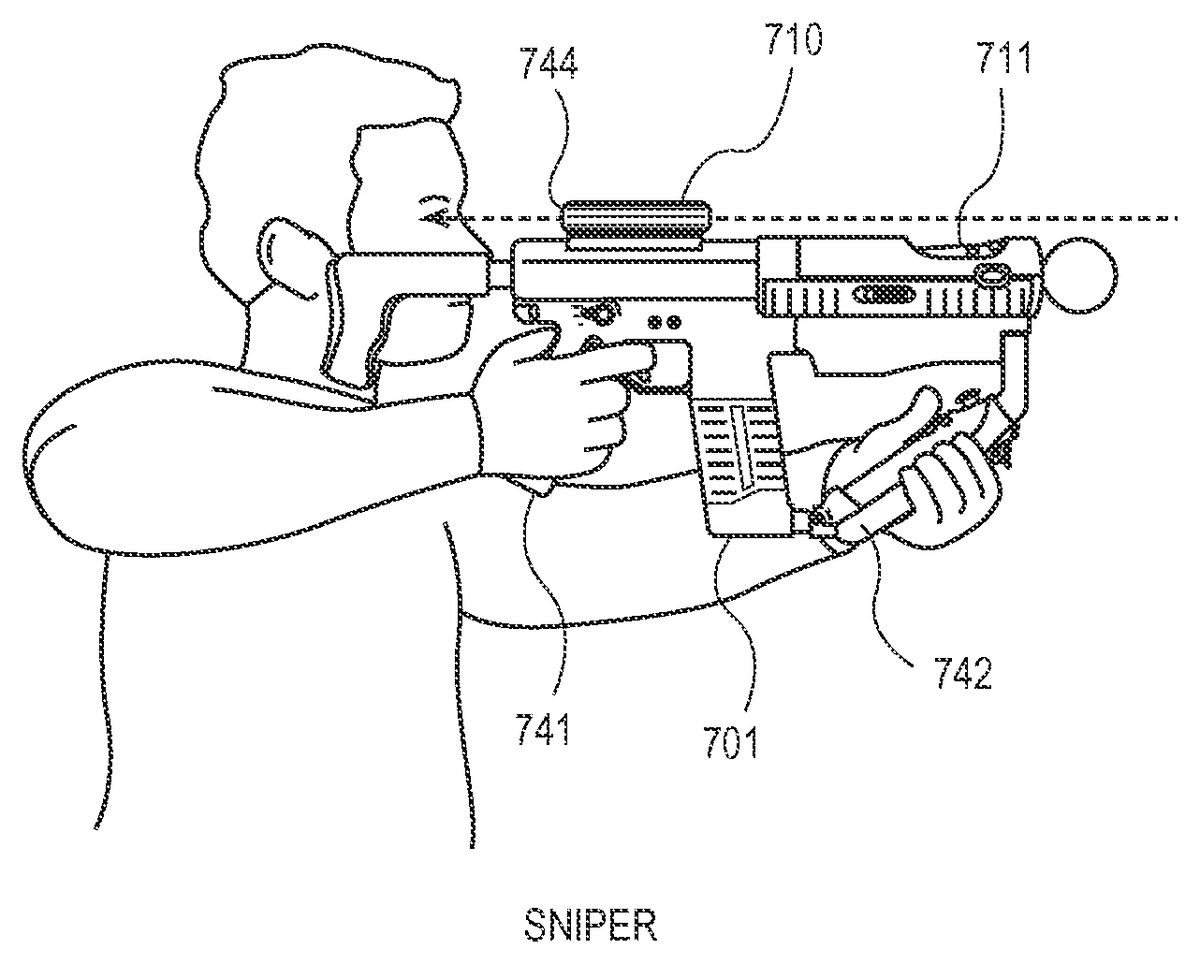
FIGS. 7-9illustrate a pistol grip, machine gun grip, and sniper grip, respectively, of a user holding a gun-like shell in accordance with embodiments. InFIG. 7, a user holds rear grip741of gun shell701. A sensor within rear grip741sends a signal through mated game controller711to a video game console, such that the video game console is informed that the user holds the smart shell as a pistol. InFIG. 8, the user holds both rear grip741and front grip742of gun shell701. A sensor within front grip742, along with the sensor within rear grip741, send signals through the mated game controller so that the video game console is informed that the user holds the shell as a machine gun. InFIG. 9, the user holds both rear grip741and front grip742, and puts targeting scope710up to his eye. A sensor near targeting scope710, along with sensors within front grip742and rear grip741, send signals through the mated game controller indicating that the user holds the gun shell as a sniper. Game play and scenes can thus be based upon how a user actually holds a game controller.
FIG. 10illustrates a rendering of a sniper view on a display in accordance with an embodiment. Sniper view1043is displayed on display1025, showing a zoomed in portion of a scene as well as target crosshairs. A barrel tunnel of the sniper scope is shown for effect. This display can occur automatically when a user places both hands on the gun grips and aligns target scope710to his or her eyes.
Utilizing 3-D television display technology, the sniper view may be synchronized with active shutter744(FIG. 9) disposed within the optical path of targeting scope710. The sniper display on the screen is synchronized to show itself only to the user looking through targeting scope710and not to other players wearing 3-D active shutter glasses. Time multiplexing of images in conjunction with different pairs of 3-D glasses can enable this. For example, the other pairs of 3-D glasses can be opaque at the instant that the sniper view is shown on the display while the active shutter in the targeting scope is transparent. At different instances, different scenes can be shown when the other 3-D glasses are transparent.
FIG. 11illustrates sensors on a gun-like smart shell and associated logic in accordance with an embodiment. Logic circuit1100fed by sensors745,746, and747determines how gun shell701is being held. Touch sensor745is embedded in rear grip741, touch sensor746is embedded in front grip742, and proximity sensor747is embedded near the rear of targeting scope710.
If rear grip741is held, but neither the other grip is held nor a part of the user's face near the targeting scope, then logic circuit1100outputs that the user holds the gun as a pistol. If both rear grip741and front grip742are held, but the targeting scope is not near the user's face, then logic circuit1100outputs that the user holds the gun as a machine gun. If rear grip741and front grip742are both held and the targeting scope is near a user's face, then logic circuit outputs that the user holds the gun as a sniper.
The NOT logic associated with each AND gate in logic circuit1100can prevent the wrong mode from being determined and minimize nuisance switching of the screen to reflect that mode. For example, if a player holds the gun as a pistol and then lowers it to his or her side, proximity sensor747may sense the thigh or leg of the user, thinking it is the user's face. However, because front grip746is not held, logic1100prevents a nuisance switch to sniper mode (and a screen view such as that inFIG. 10) from flipping up on the display.
The output from logic circuit110can be routed through an I/O port of game controller711and back to the video game console. In other embodiments, raw sensor data, without logic in the shell, can be routed to the video game console. The logic can then be implemented in the video game console.
Other sensors can be embedded in the gun to enhance gameplay, increase realism, or merely add to the entertainment value of the shell.
FIG. 12illustrates a microphone on a shell in accordance with an embodiment. Player1250utters voice commands into microphone1251on shell1201. The voice commands are routed from the microphone through an interface to an input port of game controller1211. The voice commands are then wirelessly transmitted to a video game console for processing.
For example, the player can shout “Reload!” into the microphone, and the video game can reload the player's virtual gun with more ammunition, such as bullets, grenades, or missiles. In another example, the player's whispered taunting can be transmitted to other players who are networked in. The player's voice is projected by speakers on the other players' televisions. This can be a useful alternate to headset-mounted microphones that are commonly offered for some video game consoles. A player need not don a special headset, but merely attach a smart shell to an existing controller.
FIG. 13is a flowchart illustrating process1300in accordance with one embodiment. In operation1301, a housing having a sensor is removably coupled to a game controller so that the sensor is operatively connected with an input port of the game controller. In operation1302, the sensor is activated while the housing and game controller are coupled, thereby sending a signal from the sensor to the input port of the game controller. In operation1303, a graphic event is viewed on a display screen, the graphic event occurring in response to the activation of the sensor. In operation1304, the housing is safely decoupled from the game controller.
FIG. 14is a flowchart illustrating process1400in accordance with one embodiment. In operation1401, a video game gun controller is provided having a first sensor on a first grip, a second sensor on a second grip, and a third sensor proximate to a rear of a targeting scope. In operation1402, it is determined, using the first sensor, whether a hand is against the first grip. In operation1403, it is determined, using the second sensor, whether a hand is against the second grip. In operation1404, it is determined, using the third sensor, whether a face is aligned with the targeting scope. In operation1405, based on the three determinations, wherein it is determined that a hand is against the first grip, a hand is against the second grip, and a face is aligned with the targeting scope, a game state is switched and objects rendered on a display as a sniper view.
The operations may be performed in the sequence given above or in different orders as applicable. They can be automated in a computer or other machine and can be coded in software, firmware, or hard coded as machine-readable instructions and run through one or more processors that can implement the instructions.
In the foregoing specification, the invention is described with reference to specific embodiments thereof, but those skilled in the art will recognize that the invention is not limited thereto. Various features and aspects of the above-described invention may be used individually or jointly. Further, the invention can be utilized in any number of environments and applications beyond those described herein without departing from the broader spirit and scope of the specification. The specification and drawings are, accordingly, to be regarded as illustrative rather than restrictive.
It should be noted that the methods, systems, and devices discussed above are intended merely to be examples. It must be stressed that various embodiments may omit, substitute, or add various procedures or components as appropriate. For instance, it should be appreciated that, in alternative embodiments, the methods may be performed in an order different from that described, and that various steps may be added, omitted, or combined. Also, features described with respect to certain embodiments may be combined in various other embodiments. Different aspects and elements of the embodiments may be combined in a similar manner. Also, it should be emphasized that technology evolves and, thus, many of the elements are examples and should not be interpreted to limit the scope of the invention.
Specific details are given in the description to provide a thorough understanding of the embodiments. However, it will be understood by one of ordinary skill in the art that the embodiments may be practiced without these specific details. For example, well-known circuits, processes, algorithms, structures, and techniques have been shown without unnecessary detail in order to avoid obscuring the embodiments.
Also, it is noted that the embodiments may be described as a process which is depicted as a flow diagram or block diagram. Although each may describe the operations as a sequential process, many of the operations can be performed in parallel or concurrently. In addition, the order of the operations may be rearranged. A process may have additional steps not included in the figure.
Moreover, as disclosed herein, the term “memory” or “memory unit” may represent one or more devices for storing data, including read-only memory (ROM), random access memory (RAM), magnetic RAM, core memory, magnetic disk storage mediums, optical storage mediums, flash memory devices, or other computer-readable mediums for storing information. The term “computer-readable medium” includes, but is not limited to, portable or fixed storage devices, optical storage devices, wireless channels, a sim card, other smart cards, and various other mediums capable of storing, containing, or carrying instructions or data.
Furthermore, embodiments may be implemented by hardware, software, firmware, middleware, microcode, hardware description languages, or any combination thereof. When implemented in software, firmware, middleware, or microcode, the program code or code segments to perform the necessary tasks may be stored in a computer-readable medium such as a storage medium. Processors may perform the necessary tasks.
Having described several embodiments, it will be recognized by those of skill in the art that various modifications, alternative constructions, and equivalents may be used without departing from the spirit of the invention. For example, the above elements may merely be a component of a larger system, wherein other rules may take precedence over or otherwise modify the application of the invention. Also, a number of steps may be undertaken before, during, or after the above elements are considered. Accordingly, the above description should not be taken as limiting the scope of the invention.
Claims
- A video game controller peripheral shell apparatus, comprising: a housing having a releasable mating portion;a sensor supported by the housing;and a signal interface operatively coupled with the sensor;wherein the mating portion is configured to rigidly and releasably couple the housing to a game controller having an input/output (I/O) port, the signal interface adapted to communicate a signal from the sensor through the I/O port of the game controller to a video game console and adapted to receive a signal from the video game console through the game controller I/O port.
- The apparatus of claim 1 further comprising: a tactile force generator supported by the housing and operatively coupled with the signal interface, wherein the tactile force generator is configured to receive a signal from the video game console through the I/O port and generate physical forces on the housing.
- The apparatus of claim 1 further comprising: an indicator supported by the housing, and operatively coupled with the signal interface, wherein the indicator is configured to receive a signal from the video game console through the I/O port and provide a visual or audio indication.
- The apparatus of claim 1 wherein the signal interface is configured to automatically connect to the I/O port of the game controller when the mating portion couples to the game controller.
- The apparatus of claim 1 further comprising: a second mating portion configured to releasably couple the housing to a second game controller, the shell apparatus and controllers adapted to be used in conjunction with each other during a video game.
- The apparatus of claim 1 wherein the signal interface comprises an electrical signal interface.
- The apparatus of claim 1 further comprising: a targeting scope;and an active shutter disposed within an optical path of the targeting scope, wherein the active shutter is configured to be synchronized with images on a 3D-enabled display using the received signal.
- The apparatus of claim 1 wherein the sensor comprises a microphone, and an audio signal from the microphone is thereby adapted to communicate from the sensor through the I/O port of the game controller to a video game console.
- The apparatus of claim 1 wherein the housing mating portion is configured to rigidly and releasably attach the housing to a housing of the game controller.
- The apparatus of claim 1 wherein the game controller includes a motion controller.
- The apparatus of claim 1 wherein the game controller includes a wireless controller.
- A video game controller peripheral shell apparatus, comprising: a housing having a releasable mating portion;a sensor supported by the housing;a signal interface operatively coupled with the sensor;a targeting scope;and an active shutter disposed within an optical path of the targeting scope, wherein the mating portion is configured to releasably couple the housing to a game controller having an input/output (I/O) port, the signal interface adapted to communicate a first signal from the sensor through the I/O port of the game controller to a video game console and receive a second signal from the video game console through the game controller I/O port, and the active shutter is configured to be synchronized with images on a 3D-enabled display using the received second signal.
- The apparatus of claim 12 further comprising: a tactile force generator supported by the housing and operatively coupled with the signal interface, wherein the tactile force generator is configured to receive a signal from the video game console through the I/O port and generate physical forces on the housing.
- The apparatus of claim 12 further comprising: an indicator supported by the housing, and operatively coupled with the signal interface, wherein the indicator is configured to receive a signal from the video game console through the I/O port and provide a visual or audio indication.
- The apparatus of claim 12 wherein the signal interface is configured to automatically connect to the I/O port of the game controller when the mating portion couples to the game controller.
Disclaimer: Data collected from the USPTO and may be malformed, incomplete, and/or otherwise inaccurate.