DETAILED DESCRIPTION
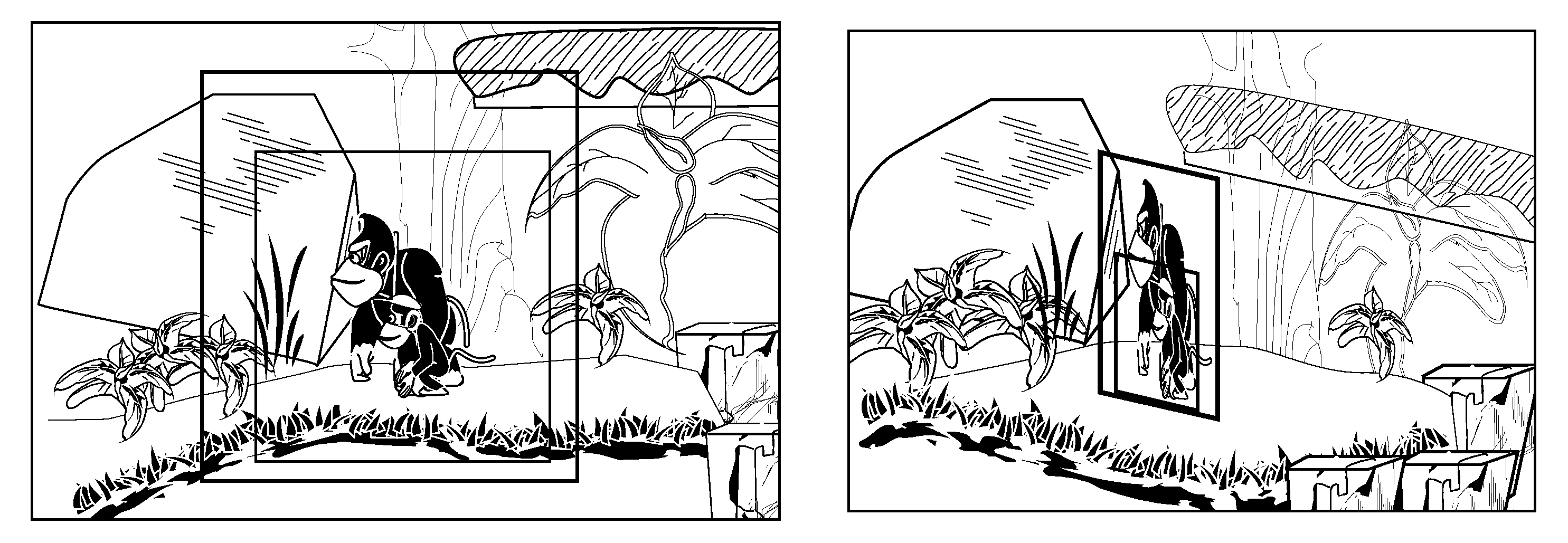
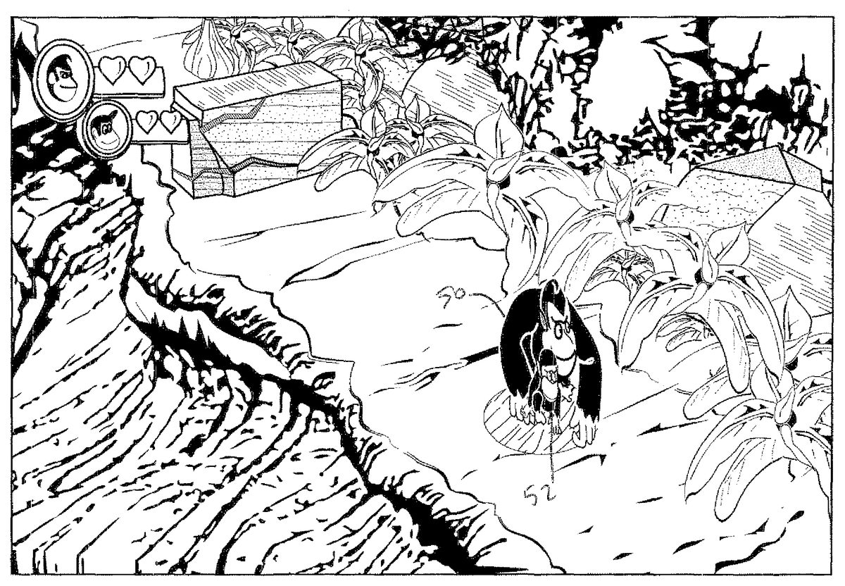
FIG. 1shows an example image40produced by a graphics and animation system1. Two animated characters (in this case a large monkey50(“Donkey Kong”) and a small monkey52(“Diddy Kong”) move through a three-dimensional world54. In one example implementation, animated character50can be controlled by one game player input, and animated character52can be controlled by another game player input. When these two animated characters50,52are controlled begin moving in tandem, they have substantially the same 3D coordinates in three dimensional space and can interfere with one another. If they were in the real world, however, the two characters50,52could never occupy exactly the same space in three dimensions but rather one might stand or walk right next to the other. Since it may not be possible in a simple multiplayer gaming environment for game players to control or worry about the depths (z) of their respective characters and in any event expect system1to provide photorealism, it is desirable that system1will be able to automatically process the two characters50,52so they remain distinct and independent characters in the resulting image.
For example, it may be that two independent game players position their respective characters so they occupy precisely the same or overlapping space in the 3D world. This can result in the two animated characters50,52appearing to be united as one single object as shown inFIGS. 1 and 2. The visual effect is aesthetically unpleasing and not realistic since in the real world the two characters would never actually merge with one another but rather would remain distinct and could never occupy exactly the same space at exactly the same time. Separating the two animated characters50,52based on their 3D polygon representations using conventional 3D collision detection and hidden surface removal techniques is possible but is relatively computationally intensive.
To efficiently avoid such undesired occurrences, the exemplary illustrative non-limiting implementation under certain circumstances subtly replaces the 3D object representations of the animated characters50,52with one or more 2D “imposter” object(s) that is common to the plural animated characters. The resulting common 2D representation is like a thin wall or billboard. The exemplary illustrative non-limiting implementation can dynamically substitute the 2D representation for the plural 3D representations if for example the plural animated 3D objects exist in substantially the same 3D coordinates or within a short distance from one another so the 3D objects overlap in 3D space.
An example resulting image based on the 3D imposter is shown inFIG. 3. In this case, plural animated characters50,52are represented by a 2D planar (e.g., texture mapped) object in which the two animated characters are drawn as if one is in front of the other and they are walking side by side. In this example, the 2D wall object or imposter represents the situation where one character52exists in front and another character50exists in back. The resulting image shows the two animated characters50,52appearing distinct from one another and not merging into one another even though their 3D representations may overlap or even be coextensive in 3D space.
FIG. 4shows the image resulting from the 2D wall object or imposter from a different viewpoint.FIG. 4thus illustrates what is actually going on—namely that the plural characters50,52are being imaged based on a common 2D representation that appears like a thin wall or billboard. For example, the 2D object may comprise a planar surface such as a quad in 3D space, and the images of the plural characters may be texture mapped onto the planar surface. Transparency and alpha blending may be used to ensure that portions of the 2D object not occupied by part of the image of characters50,52may be “see through” so as not to obstruct the user's view of objects behind the planar object in 3D space. Thus, the two characters50,52are in fact occupying the very same (planar) space in the 3D world, but the resulting image seen by the user makes the two characters appear to be distinct and non-interfering due e.g. to the ultimate 2D projection used for generating a display.
In exemplary illustrative non-limiting implementations, the user's viewpoint is restricted so the user never sees the animated characters50,52from viewpoints such as shown inFIG. 4. Rather, in the exemplary illustrative non-limiting implementation, viewpoint is restricted to be generally perpendicular to the orientation of the plane of the common 2D object whenever the 2D representation is used in place of the 3D representations. For example, if the user is able to and begins to change the viewpoint in an interactive system so that the viewpoint is no longer substantially perpendicular to the 2D imposter, the system can subtly switch to 3D representations of the animated characters50,52to preserve photorealism. Then, if the user changes the viewpoint again to provide substantial perpendicularly to the 2D imposter model, the system can again subtly substitute the 2D model for the 3D models. Similarly, as shown inFIG. 5, if the animated characters50,52are controlled such that are no longer occupying the same space, the system can begin representing the characters with respective 3D models and cease using the common 2D representation.
Exemplary Graphics & Animation Rendering System
With reference toFIG. 6A, an exemplary illustrative non-limiting animation and graphics generation system1is shown in an external view of the game system1. As shown inFIG. 6A, the system1includes a television receiver (hereinafter, simply referred to as a “television”) or other display2, a processing unit apparatus3, an optical disc4, one or plural input device(s)8(e.g., one for each of multiple players), and a marker section6. In this system, the processing unit3performs an animation and graphic generation process in response to a user manipulation of input devices8, but in other implementations that system1does not necessarily need to respond in real time to user input in an interactive manner but can instead generate graphics based on a predetermined schedule e.g., to show a movie or video presentation.
In the system3, the optical disc4typifying an information storage medium used for the system3in an exchangeable manner is detachably inserted. A program executed by the system3is stored in the optical disc4. The system3has, on the front surface thereof, an insertion opening for the optical disc4. The system3reads and executes the game program stored in the optical disc4which is inserted through the insertion opening, so as to perform the game process. Other implementations can store the program on any volatile or non-volatile storage device including a ROM cartridge, a flash memory, a downloadable RAM memory, etc.
The system3is connected to the television2, which is an exemplary display device, through a connecting cord. A game image obtained as a result of the process performed by the system3is displayed on the television2. Further, the marker section6is provided on the periphery (inFIG. 6A, on a portion above a screen) of a screen of the television2. The marker section6includes two markers6R and6L on both ends thereof. Specifically, the marker6R (as well as the marker6L) includes one or more infrared LED, and emits an infrared light forward from the television2. The marker section6is connected to the system3, and the system3is able to control each infrared LED of the marker section6so as to light each infrared LED up.
The input device8provides the system3with operation data representing a content of an operation performed on the input device8itself. In the present embodiment, the input device8includes a controller5and an accelerometer and/or gyro sensor (inertial measurement) unit7. As described in detail below, the input device8is structured such that the sensor unit7may be detachably connected to the controller5or alternatively can be built into the controller. Radio communication is used between the controller5and the system3. The radio communication between the controller5and the system3is uses, for example, Bluetooth (Registered Trademark) technology. In another embodiment, connection between the controller5and the system3may be a wired connection.
Next, an internal structure of the system3will be described with reference toFIG. 6B.FIG. 6Bis a block diagram illustrating a structure of the system3. The system3includes the CPU10, a system LSI11, an external main memory12, a ROM/RTC13, a disk drive14, an AV-IC15, and the like.
The CPU10, functioning as an animation processor, performs a process by executing the program stored in the optical disc4. The CPU10is connected to the system LSI11. To the system LSI11, the external main memory12, the ROM/RTC13, the disk drive14, and the AV-IC15as well as the CPU10are connected. The system LSI11performs processes for controlling data transmission between the respective components connected thereto, generating an image to be displayed, acquiring data from an external device, and the like. The internal structure of the system LSI will be described below. The external main memory12of a volatile type stores a program such as a program read from the optical disc4and a program read from a flash memory17, and various data, and the external main memory12is used as a work area and a buffer area for the CPU10. The ROM/RTC13includes a ROM (so-called a boot ROM) incorporating a boot program for the system3, and a clock circuit (RTC: Real Time Clock) for counting time. The disk drive14reads program data, texture data, and the like from the optical disk4, and writes the read data into an internal main memory11eor the external main memory12described below.
The system LSI11includes an input/output processor (I/O processor)11a, a GPU (Graphics Processor Unit)11b, a DSP (Digital Signal Processor)11c, a VRAM11d, and the internal main memory11e. These component11a,11b,11c,11d, and11eare connected with each other through an internal bus, which is not shown.
The GPU11b, acting as a part of rendering means, generates an image in accordance with a graphics command (rendering command) from the CPU10. The VRAM11dstores data (data such as polygon data and texture data) necessary for the GPU11bto execute the graphics command. Such GPU processing can include for example texture mapping, projection of 3D surfaces on a 2D viewing plane, shading, lighting, rasterization, etc. as well known to those skilled in the art. When an image is generated, the GPU11bgenerates image data by using data stored in the VRAM11d.
The DSP11c, functioning as an audio processor, generates audio data by using sound data and sound waveform (tone quality) data stored in the internal main memory11eor the external main memory12.
The image data and the audio data generated as described above are read by the AV-IC15. The AV-IC15outputs the read image data to the television2through an AV connector16, and outputs the read audio data to a speaker2aincorporated in the television2. Thus, an image is displayed on the television2, and a sound is outputted from the speaker2a.
The input/output processor11aperforms data transmission to and data reception from the component connected thereto, and download of data from an external device. The input/output processor11ais connected to the flash memory17, a wireless communication module18, a wireless controller module19, an extension connector20, and a memory card connector21. The wireless communication module18is connected to an antenna22, and the wireless controller module19is connected to an antenna23.
The input/output processor11ais connected to a network via the wireless communication module18and the antenna22, so as to communicate with another system and various servers connected to the network. The input/output processor11aregularly accesses the flash memory17, and detects for data which needs to be transmitted to the network, and transmits, when the data is detected, the data to the network through the wireless communication module18and the antenna22. Further, the input/output processor11areceives data transmitted from another system, and/or download data from a download server, through the network, the antenna22, and the wireless communication module18, and stores the received data and/or the downloaded data in the flash memory17. The CPU10executes a game program so as to read data stored in the flash memory17and use the data on the game program. The flash memory17may store saved data (game result data or intermediate step data) of a game played by using the system3in addition to data transmitted from the system3to another system or the various servers, and data received by the system3from another system or the various servers.
The input/output processor11areceives operation data transmitted from the controller5through the antenna23and the wireless controller module19, and (temporarily) stores the received operation data in a buffer area of the internal main memory11eor the external main memory12.
Further, the input/output processor11ais connected to the extension connector20and the memory card connector21. The extension connector20is a connector for interface, such as a USB or a SCSI, and allows communication with the network by connecting thereto a media such as an external storage media, connecting thereto a peripheral device such as another controller, and/or connecting thereto a wired communication connector, without using the wireless communication module18. The memory card connector21is a connector for connecting thereto an external storage media such as a memory card. For example, the input/output processor11aaccesses an external storage media through the extension connector20or the memory card connector21so as to store data in the external storage media or read data from the external storage media.
The system3includes a power button24, a reset button25, and an eject button26. The power button24and the reset button25are connected to the system LSI11. When the power button24is on, power is supplied to the respective components of the system3through an AC adaptor not shown. When the reset button25is pressed, the system LSI11reboots a boot program of the system3. The eject button26is connected to the disk drive14. When the eject button26is pressed, the optical disc4is ejected from the disk drive14.
Exemplary 2D Models or Imposters
FIG. 7Ashows respective 2D images for two respective characters50,52. These respective 2D images or “cels” can be derived from or used to create respective sprite sheets, i.e., collections or sequences of 2D images of each character in different positions that can be used to supply animation. In one example implementation, theFIG. 7A2D images can be dynamically generated by processor10or GPU11bprojecting 3D models of the two characters50,52to create corresponding 2D images (with surrounding alpha transparency) and storing these images in VRAM11das texture map(s) for texture mapping by GPU11b.FIG. 7A-1shows exemplary such sprite sheet texture maps T1, T2obtained by projecting 3D representations of the two characters50,52onto flat surfaces—essentially by removing the Z (depth) coordinate and overwriting based on closer Z having priority.
Such cels as shown inFIG. 7Acan be combined to create an imposter 2D data structure shown inFIG. 7B. In the example shown, the 2D images are superimposed onto one another with the 2D image of the character in front by e.g., overwriting the 2D image of the character in back. If desired, this superimposition can be performed without any collision detection since which image is in front and which is behind can be predetermined and fixed, by for example multi-texturing or by superimposing the two images before texture mapping. One way of looking at what is happening is that the two 3D models of the respective characters50,52are projected (“flattened”) onto the same 3D planar surface, with the software declaring one of the characters (e.g., the smaller one52) “in front” and thus overwriting conflicting pixels or texels of the other character to provide appropriate hidden surface removal.
The resulting 2D image(s) can be texture-mapped onto a quad or other planar surface (e.g., a rectangle or a pair of triangles sharing a common side) positioned in the 3D world as shown inFIG. 7C. Then, the viewing frustum can be constrained to be in the direction as shown inFIG. 7Drelative to the quad to ensure photorealism. During image generation, a sequence of 2D “cel” images from a sprite sheet or the like can thus be texture-mapped onto the 2D object to provide animation effects.
FIG. 8is a flowchart of exemplary illustrative non-limiting computer controlled steps for performing animation as described herein. The steps shown inFIG. 8are represented by computer instructions that are stored in a volatile or non-volatile memory device and executed by the animation system processor10to effect animation. Here's how theFIG. 8process flow works in the exemplary illustrative non-limiting implementation:
1. For each player P:
Store Sorting Layer Info in ImposterBin (the Imposter System) (block302) (e.g., if character52is supposed to be in front of character50when the two are travelling in tandem)
2. For each object pair A, B:
Do 3D Bounds of A and B overlap? (block304) (this test can be performed e.g., using for example a 3D bounding box test)
NO: Draw A and B as normal 3D objects based on typical 3D representations (block306).
YES: Store Sorting Layer Info of A and B in ImposterBin (block308) (this information can also be used to define the depth of a 2D surface in the 3D world so the imaged objects A and B can be behind some world objects and in front of some other world objects).
3. For each entry in ImposterBin:
Project Bounds to Screen (block310)Are bounds on screen and fit in sprite sheet? (block312)NO: Fall back to normal 3D rendering (block314) since 3D rendering tools can be used e.g., to perform cut plane processing etc.YES (bound are on screen and fit in sprite sheet):Create projection around screen slot (block316)Reserve Slot in Sprite Sheet (block318)Draw the entry into the sprite sheet slot (block320).(The above-described three operations316,318,320accomplish dynamic 2D conversion of a 3D model(s) or other asset, and in some implementations can thus project a 3D model onto a 2D surface in order to dynamically create a sprite(s) such that animation can be processed in 3D and the graphics generation system downstream determines whether to render using the 3D models or whether to create a 2D imposter model instead).
4. Then, for each entry in ImposterBin in order of desired depth sort:
Reverse Projection screen box into world plane (block322).
Draw camera facing quad (i.e., the 2D surface can be defined with different orientation depending on virtual camera location) with sprite sheet texture cell (block324).
FIG. 7Eshows an exemplary illustrative special effect that can allow the 2D representation to interact with other objects in the 3D world. In this example, z-bias hardware (see U.S. Pat. No. 6,664,958 entitled Z-Texturing, incorporated herein by reference) can be used to provide a “jumping through” effect that allows the two animated characters50,52to appear to jump through an obstacle together while still being represented using the common 2D representation defined with a single common depth value Z.
While the technology herein has been described in connection with exemplary illustrative non-limiting embodiments, the invention is not to be limited by the disclosure. For example, the technology herein is applicable to real time or non-real time animation generation, interactive or non-interactive systems, video games, computer games, web page animation presentations, handheld devices such as cell phones, television and movies, or any application where computer generated animation is used. The invention is intended to be defined by the claims and to cover all corresponding and equivalent arrangements whether or not specifically disclosed herein.