U.S. Pat. No. 8,409,018
GAME CONTROLLER AND METHOD FOR HARVESTING USER ENERGY EXPENDED WHILE PLAYING A GAME
AssigneeToshiba Samsung Storage Technology Korea Corporation
Issue DateAugust 19, 2011
Illustrative Figure
Abstract
A game controller, a game machine, and a game system using the game controller is provided. The game controller manipulates a game program, and includes an energy harvesting unit to harvest motion of a user as energy when a game is played and an energy storing unit to store the energy harvested by using the energy harvesting unit.
Description
Throughout the drawings and the detailed description, unless otherwise described, the same drawing reference numerals will be understood to refer to the same elements, features, and structures. The relative size and depiction of these elements may be exaggerated for clarity, illustration, and convenience. DETAILED DESCRIPTION The following detailed description is provided to assist the reader in gaining a comprehensive understanding of the methods, apparatuses, and/or systems described herein. Accordingly, various changes, modifications, and equivalents of the systems, apparatuses and/or methods described herein will be suggested to those of ordinary skill in the art. Also, descriptions of well-known functions and constructions may be omitted for increased clarity and conciseness. FIG. 1illustrates a game controller100according to an example embodiment.FIG. 2is a block diagram of the game controller100ofFIG. 1. Referring toFIG. 1, the game controller100may include a body portion110, a moving portion120, and a grip portion130. The body portion110may be configured with portions bent in different directions. For example, according to an example embodiment as shown inFIG. 1, the body portion110may have two portions at opposite ends of the body portion110bent in different directions. The body portion110and the grip portion130may be coupled to each other. A manipulation button140may be formed in a portion of the body portion110between the two bent portions. The manipulation button140may function as a trigger portion of the game controller100. For example, in the case that the game controller100is configured to resemble a rifle, the manipulation button140may function as the trigger. The moving portion120may be configured on the game controller100to move linearly relative to the body portion110. As mentioned, by way of example, the game controller100may resemble a pump action rifle in which case a first end of the body portion110may be a muzzle, the moving portion120may resemble a hand grip portion of the rifle that moves forwards and backwards ...
Throughout the drawings and the detailed description, unless otherwise described, the same drawing reference numerals will be understood to refer to the same elements, features, and structures. The relative size and depiction of these elements may be exaggerated for clarity, illustration, and convenience.
DETAILED DESCRIPTION
The following detailed description is provided to assist the reader in gaining a comprehensive understanding of the methods, apparatuses, and/or systems described herein. Accordingly, various changes, modifications, and equivalents of the systems, apparatuses and/or methods described herein will be suggested to those of ordinary skill in the art. Also, descriptions of well-known functions and constructions may be omitted for increased clarity and conciseness.
FIG. 1illustrates a game controller100according to an example embodiment.FIG. 2is a block diagram of the game controller100ofFIG. 1.
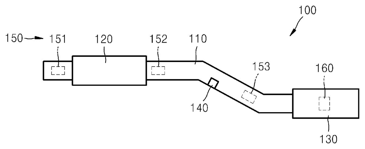
Referring toFIG. 1, the game controller100may include a body portion110, a moving portion120, and a grip portion130.
The body portion110may be configured with portions bent in different directions. For example, according to an example embodiment as shown inFIG. 1, the body portion110may have two portions at opposite ends of the body portion110bent in different directions. The body portion110and the grip portion130may be coupled to each other. A manipulation button140may be formed in a portion of the body portion110between the two bent portions. The manipulation button140may function as a trigger portion of the game controller100. For example, in the case that the game controller100is configured to resemble a rifle, the manipulation button140may function as the trigger. The moving portion120may be configured on the game controller100to move linearly relative to the body portion110. As mentioned, by way of example, the game controller100may resemble a pump action rifle in which case a first end of the body portion110may be a muzzle, the moving portion120may resemble a hand grip portion of the rifle that moves forwards and backwards to load bullets in a pump action type rifle, and the grip portion130may resemble a shoulder portion of the rifle.
Referring toFIG. 2, a coil122may be installed in the moving portion120, and a permanent magnet111may be installed in the body portion110. However, an example embodiment is not limited thereto and the positions of the coil122and the permanent magnet111may be switched, for example, such that the coil122may be in the body portion110and the permanent magnet111may be in the moving portion120. The coil122and the permanent magnet111may be moved linearly relative to each other and form a linear generator. The linear generator may have a well-known structure.
When a user plays a shooting game by using the game controller100, and while the user emulates a motion of loading of a bullet, the moving portion120moves relative to the body portion110. Accordingly, the coil122and the permanent magnet111may also move relative to each other generating an electromotive force in the coil122by electromagnetic interaction. The electromotive force may be dependent on motion of the moving portion120, and thus, rectified via a rectifying circuit115to generate a constant voltage. A current passed through the rectifying current115passes through a charging circuit116and may be charged in a charger117. The rectifying circuit115, the charging circuit116, and the charger117may have well-known structures.
Electric energy charged in the charger117may be supplied, for example, to a reaction force generator118to be used as energy for generating a reaction force. The electric energy charged in the charger117may also be used for other manipulations of the game controller100.
Furthermore, a battery (not shown) for supplying power may be formed in the game controller100. Either the charger117or the battery may be used as an auxiliary element.
A moving state detection unit150may be formed in the body portion110. The moving state detection unit150may include a plurality of detection sensors151,152, and153arranged at predetermined intervals and positions in the body portion110. The detection sensors151,152, and153may be configured to individually or collectively detect directions of linear motion, planar motion or three-dimensional motion. For example, the detection sensors151,152, and153may be a 1-axis inertial sensor, a 2-axis inertial sensor, or a 3-axis inertial sensor. In this case, the detection sensors151,152, and153may be located at different locations in the body portion110from a predetermined rotational center. As such, the detection sensors151,152, and153may be configured to have different accelerations so that their rotational amounts may be detected.
The detection sensors151,152, and153may be provided in the body portion110to detect the movement and motion of the body portion110. By detecting the motion of the body portion110, the moving state detection unit150may function, for example, as an input unit that recognizes an operation and action performed the user to manipulate game programs being executed. For example, in the case in which the user may be playing a shooting game, the moving state detection unit150may detect a position or a direction of the muzzle portion of the body portion110when shooting.
A reaction force generating unit160may be formed in the grip portion130.
FIG. 3illustrates the reaction force generating unit160according to an example embodiment. Referring toFIG. 3, the reaction force generating unit160may include two vibration motors162and164spaced apart in the grip portion130. The vibration motors162and164may respectively include weights163and165at positions away from a rotational axis of the vibration motors162and164. As such, when the vibration motors162and164rotate, vibration may be generated according to rotation of the weights163and165. For example, when the weights163and165are sequentially directed in one direction, the effect may be the same as a reaction force generated in that direction. In other words, the reaction force generating unit160may allow the user to experience a touch sensation in response to the contents and experiences of a game. That is, a reaction force may be generated in the reaction force generating unit160when the manipulation button140is pressed to sensationalize an act of shooting.
As illustrated inFIG. 1, the reaction force generating unit160may be formed in the grip portion130. However, an aspect of the example embodiment may not be limited thereto and may include additional reaction force generating units. For example, as illustrated inFIG. 4, other reaction force generating units166,167, and168may be spaced apart at predetermined intervals in the body portion110. A direction of the reaction force of the reaction force generating units166,167, and168may be set to be a predetermined direction of the body portion110so that a sensation due to the reaction force being transferred along the predetermined direction of the body portion110may be realized.
A magnitude of the reaction force may correspond to game contents. As such, since the reaction force generating unit160may generate a large reaction force according to game contents, energy for generating the reaction force may not be supplied just from the battery. Thus, the game controller100according to an example embodiment may convert motion of the user into electric energy and use the electric energy. Accordingly, additional energy may be charged in and supplied from the charger117so that the user may experience sufficient body sensation when playing a game.
According to an aspect of the example embodiment described above, the reaction force generating unit160may be installed in the body portion110so that the user experiences the physical sensation of the game. However, an example embodiment may not be limited to the reaction force generating unit160, and instead may be configured with another vibration unit installed in the body portion110and capable of generating vibration according to the game contents.
At least one of the body portion110and the grip portion130may include a wireless or wired transmitting/reception unit for transmitting/receiving a signal to/from a computer (for example, a game machine main body520ofFIG. 10) for executing a game program. Alternatively, at least one of the body portion110and the grip portion130may include a computer for executing a game program and the game controller100may be a game machine capable of independently executing a game program.
FIG. 5illustrates a game controller200according to another example embodiment.FIG. 6illustrates an example of a flexible structure of the game controller200ofFIG. 5.
Referring toFIG. 5, the game controller200may include a body portion210, a moving portion120, and a grip portion130.
According to an example embodiment, the body portion210of the game controller200may have a flexible structure. As such, the body portion210may be deformable and configured to have a plurality of forms. That is, the body portion210may be deformed to have various forms such as, for example, a straight line, a straight line having two portions bent in different directions, a circle, and a circle having a grip. For example, the body portion210may include a first coupling unit271and a second coupling unit272respectively formed at a first end and second end of the body portion210. The first coupling unit271and the second coupling unit272may be coupled to each other so that the game controller200may maintain a circular shape like that of, for example, a steering wheel. The body portion210may be configured to maintain the deformed form, return to a previous deformed form, or an initial structure. At least a portion of the body portion210may be configured to have a shape such that the moving portion120moves relative to the body portion210.
FIG. 6illustrates an example embodiment of the flexible structure of the body portion210. Referring toFIG. 6, a plurality of frames, for example, first through third frames211,212, and213being serially arranged, may constitute a multi-joint structure rotatably coupled to one another. First and second fixing links214and215and first through third moving links216,217, and218may be formed along two lines of a central line that passes through rotational axes R1and R2of the frames211,212, and213. A first end of the first fixing link214and a first end of the second moving link216may be rotatably fixed to the first frame211at a front end. Also, in the second frame212, long grooves212aand212bextended in a lengthwise direction of the second frame212may be formed on two sides of the central line passing through the rotational axes R1and R2. Long grooves213aand213bextended in a length direction of the third frame213may be formed on two sides of the central line passing through the rotational axes R1and R2in the third frame213. A pin219athat rotatably couples a second end of the first fixing link214and a first end of the second fixing link215may be inserted into the long groove212ato move linearly in a lengthwise direction of the long groove212a. A pin219bthat rotatably couples a second end of the second fixing link215to the third frame213may be inserted into the long groove213ato move linearly in a lengthwise direction of the long groove213a. A pin219cthat rotatably couples a second end of the first moving link216to a first end of the second moving link217may be inserted into the long groove212bto move linearly in a lengthwise direction of the long groove212b. A pin219dthat rotatably couples a second end of the second fixing link215to a first end of the third moving link218may be inserted into the long groove213bto move linearly in a lengthwise direction of the long groove213b. A position of the third moving link218may be selectively fixed using a separate fixing unit such as, for example, a screw, a pin, or the like.
When moving the third moving link218in the body portion210having the above-described structure, a portion of each of the first, second, and third frames211,212, and213may move around the rotational axes, and thus, the first, second, and third frames211,212, and213may bend. According to an example embodiment in which the third moving link218may be fixed, a bent shape of the first, second, and third frames211,212, and213may be fixed. WhileFIG. 6illustrates a multi-joint structure formed of three frames (first, second, and third frames211,212, and213), an example embodiment may not be limited thereto. For example, an aspect of an example embodiment may provide a body portion in which a plurality of second frames212may be serially connected. The body portion210having a multi-joint structure as described above may be deformed to have a shape according to the contents of a game as will be described later.
FIG. 6illustrates an example embodiment of a flexible structure of the body portion210. However, an example embodiment may not be limited thereto. For example, a multi-joint device having a fixing element formed at each joint, or other fixable structures may be used as the flexible structure of the body portion210. That is, the body portion210may have a multi-joint structure with a fixing element formed at each joint and each joint may be independently rotated such that the body portion210may have a plurality of shapes.
In the case in which a user plays a game that may require shooting a gun, the body portion210having the above-described flexible structure may have a straight linear shape having two portions bent in different directions, as illustrated inFIG. 1. Also, for example, in the case in which a user plays a game that may require a straight-line type instrument such as fencing or golf, the game controller200may manipulate the game by using the body portion210having a straight linear shape as illustrated inFIG. 5. Alternatively, in the case that a user plays a game that may require a circular steering wheel such as car driving or airplane operating, the game controller100may manipulate the game by using the body portion210having a circular shape like a steering wheel. In addition, games may be manipulated by modifying the body portion210to other various shapes according to the characteristics of the game to play.
The above-described body portion210having a flexible structure deformable to have a plurality of various forms may not be limited thereto.FIG. 7illustrates an example of a deformable shape of a body portion of the game controller200ofFIG. 5. For example, as illustrated inFIG. 7, a body portion310may be formed of frames311,313, and315including two rotatable joint portions312and314. Permanent magnets M1and M2may be attached to one of the rotatable joint portions312and314and a coil C may be attached to another of the rotatable joint portions312and314to rotate relative to each other. The permanent magnets M1and M2and the coil C illustrates an example of a rotational generator. By moving the frames311,313, and315, the permanent magnets M1and M2and the coil C may move relative to each other, and an electromotive force may be generated in the coil C by electric interaction therebetween. As described with reference toFIG. 2, the electromotive force generated by motion of the user may be passed through the rectifying circuit115and the charging circuit116and then may be charged in the charger117for reuse. The frames311,313, and315illustrated as being bendable as described above may resemble a fitness instrument, and thus, a game controller including the body portion310as described above may be used when playing a fitness game.
FIG. 8illustrates a body portion410, according to another example embodiment of a body portion. Referring toFIG. 8, the body portion410may include a body411and a piezoelectric layer412. The body411may be elastic and configured in a rod shape. The piezoelectric layer412may be attached to at least a portion of the body411. As such, when the body411bends, the piezoelectric layer412also bends. When the user bends the body411as illustrated inFIG. 9, the piezoelectric layer412may generate an electromotive force by a piezoelectric effect in accordance with bending of the body411. As described with reference toFIG. 2, the electromotive force generated by motion of the user may pass through the rectifying circuit115and the charging circuit116and may then be charged in the charger117for reuse. The body portion410illustrated as being bendable as described above may resemble a fitness instrument, and thus, a game controller including the body portion410as described above may be used when playing a fitness game.
FIG. 10illustrates a game system according to an example embodiment.FIG. 11is a block diagram illustrating the game system ofFIG. 10.
Referring toFIGS. 10 and 11, the game system may include a game controller510, a game machine main body520, and a display device530.
The game controller510may be the game controller100or200described with reference toFIGS. 1 through 9. The game controller510may include an input unit511like the manipulation button140as shown inFIG. 1or the moving state detection unit150as shown inFIG. 1, a transmission/reception unit515that transmits or receives data to/from the game machine main body520, and a charger517for storing motion of the user as energy. Furthermore, as described above, the game controller510may include the reaction force generating unit160as shown inFIG. 1so that a user may experience a touch sensation.
The game machine main body520may include a transmission/reception unit521transmitting/receiving data to/from the game controller510, a calculation unit523(for example, a computer) executing game programs, and an input/output unit525outputting game contents as an image signal or a sound signal. The game machine main body520may be an exclusive game device or an all-purpose computer. When the game controller510includes the reaction force generating unit160so that the user experiences the touch sensation as described above, the game machine main body520may transmit an appropriate reaction force signal to the game controller510according to the contents of the games.
The display device530may include an input/output unit531receiving an image signal and a sound signal transmitted by the game machine main body520, a display unit533displaying an image according to the image signal, and a speaker535outputting a sound according to the sound signal. Alternatively, the speaker535may be included separately.
The game controller510and the game machine main body520may be connected in a wireless manner. Since the game controller510includes the charger517which harvests motion of the user as energy and stores the energy, even when the game controller510and the game machine main body520connect in a wireless manner, power used for operating the game controller510may be supplied from the charger517. A battery (not shown) for supplying power may be further included in the game controller510. Either the charger517or the battery may be used as an auxiliary element. As described above, in the case that the reaction force generating unit160(seeFIG. 3) may require generating a large reaction force according to the contents of games, additional energy may be supplied from the charger517where sufficient energy cannot be supplied just from the battery.
Wireless transmission/reception between the game controller510and the game machine main body520may be connected as illustrated inFIGS. 10 and 11. According to an aspect of an example embodiment, the game controller510and the game machine main body520may also be connected to each other via a wire. With the game controller510and the game machine being connected via a wire, for example, electric energy may be supplied via the wire, and the charger517may be used as an auxiliary element.
Also, the game machine main body520and the display device530may be connected in a wired or wireless manner. The game machine main body520and the display device530may be separately formed as shown inFIGS. 10 and 11but may also be formed as a single unit.
The game controller510and the game machine main body520according to an example embodiment may be separately formed but may not be limited thereto. A computer for executing a game program may be mounted in the game controller510. As such, the game controller510may function as a game machine. Moreover, a display device may also be mounted in the game controller510, and thus, the game controller510may be function as a portable game machine.
The linear generator, the rotational generator or the piezoelectric generator described in the above example embodiments may be examples of an energy harvesting element. However, example embodiments may not be limited thereto. For example, various other types of energy harvesting elements may be used in a game controller according to the example embodiments.
According to example embodiments, game controllers may be capable of securing energy needed for realizing a tactile reaction to improve a physical sensation when playing a game, game machines, and game systems using the game controllers.
Program instructions to perform a method described herein, or one or more operations thereof, may be recorded, stored, or fixed in one or more computer-readable storage media. The program instructions may be implemented by a computer. For example, the computer may cause a processor to execute the program instructions. The media may include, alone or in combination with the program instructions, data files, data structures, and the like. Examples of computer-readable media include magnetic media, such as hard disks, floppy disks, and magnetic tape; optical media such as CD ROM disks and DVDs; magneto-optical media, such as optical disks; and hardware devices that are specially configured to store and perform program instructions, such as read-only memory (ROM), random access memory (RAM), flash memory, and the like. Examples of program instructions include machine code, such as produced by a compiler, and files containing higher level code that may be executed by the computer using an interpreter. The program instructions, that is, software, may be distributed over network coupled computer systems so that the software is stored and executed in a distributed fashion. For example, the software and data may be stored by one or more computer readable recording mediums. Also, functional programs, codes, and code segments for accomplishing the example embodiments disclosed herein can be easily construed by programmers skilled in the art to which the embodiments pertain based on and using the flow diagrams and block diagrams of the figures and their corresponding descriptions as provided herein. Also, the described unit to perform an operation or a method may be hardware, software, or some combination of hardware and software. For example, the unit may be a software package running on a computer or the computer on which that software is running.
A computing system or a computer may include a microprocessor that is electrically connected with a bus, a user interface, and a memory controller. It may further include a flash memory device. The flash memory device may store N-bit data via the memory controller. The N-bit data is processed or will be processed by the microprocessor and N may be 1 or an integer greater than 1. Where the computing system or computer is a mobile apparatus, a battery may be additionally provided to supply operation voltage of the computing system or computer. It will be apparent to those of ordinary skill in the art that the computing system or computer may further include an application chipset, a camera image processor (CIS), a mobile Dynamic Random Access Memory (DRAM), and the like. The memory controller and the flash memory device may constitute a solid state drive/disk (SSD) that uses a non-volatile memory to store data.
A number of examples have been described above. Nevertheless, it will be under stood that various modifications may be made. For example, suitable results may be ach ieved if the described techniques are performed in a different order and/or if components in a described system, architecture, device, or circuit are combined in a different manner and/or replaced or supplemented by other components or their equivalents. Accordingly, other implementations are within the scope of the following claims.
Claims
- A game controller to manipulate a game program, comprising: an energy harvesting unit configured to harvest motion of a user as energy when playing a game;and an energy storing unit configured to store the energy harvested by the energy harvesting unit;a body portion, at least a portion thereof being deformable to have a plurality of forms;and a moving portion movable relative to the body portion, wherein the energy harvesting unit comprises a fixed magnet and a coil movable relative to the fixed magnet, and one of the fixed magnet and the coil is formed in the body portion, and the other of the fixed magnet and the coil is formed in the moving portion.
- The game controller of claim 1 , wherein the energy harvesting unit comprises an elastic body and a piezoelectric layer attached to the elastic body.
- The game controller of claim 1 , wherein the energy storing unit comprises a rectifying circuit configured to rectify the voltage of electric energy generated in the energy harvesting unit, a storage component configured to store electrical energy, and a charger configured to apply the rectified voltage to the storage component so as to charge the storage component.
- The game controller of claim 1 , further comprising a reaction force generating unit to generate a reaction force according to contents of the game, and the reaction force generating unit uses electric energy stored in the energy storing unit.
- The game controller of claim 1 , further comprising a game manipulation unit via which manipulation of the game by the user is input, wherein the game manipulation unit comprises at least one of a manipulation button and an operation recognizing sensor.
- The game controller of claim 5 , further comprising a computer to execute the game program, according to a signal input to the game manipulation unit.
- The game controller of claim 1 , further comprising: a battery configured to store energy, wherein each of the battery and the energy storing unit are configured to provide stored energy to the game controller.
- The game controller of claim 1 , further comprising a transmission/reception unit to transmit/receive data to/from a computer for executing the game program.
- A game controller to manipulate a game program, the game controller comprising: an energy harvesting unit configured to harvest motion of a user as energy when playing a game;an energy storing unit configured to store the energy harvested by the energy harvesting unit;a body portion, at least a portion thereof being deformable to have a plurality of forms;and a moving portion movable relative to the body portion, wherein the energy harvesting unit is one of a linear generator and a rotational generator comprising a fixed magnet and a coil movable relative to the fixed magnet, and one of the fixed magnet and the coil is formed in the body portion, and the other of the fixed magnet and the coil is formed in the moving portion.
- The game controller of claim 9 , wherein the body portion comprises a fixable multijoint structure.
- The game controller of claim 9 , wherein the plurality of forms comprise a straight line, a straight line having two portions bent in different directions, a circle, and a circle having a grip.
- A game controller to manipulate a game program, the game controller comprising: an energy harvesting unit configured to harvest motion of a user as energy when playing a game;and an energy storing unit configured to store the energy harvested by the energy harvesting unit, wherein the energy harvesting unit is one of a linear generator and a rotational generator comprising a fixed magnet and a coil movable relative to the fixed magnet, the game controller is in the form of a pump action rifle having a hand grip movable in a lengthwise direction of a body of a gun barrel, and one of the fixed magnet and the coil is formed in the body of the gun barrel, and the other of the fixed magnet and the coil is formed in the hand grip.
- A game machine comprising: a game manipulation unit via which a manipulation of a game by a user is input;an energy harvesting unit configured to harvest motion of the user as energy when the game is played;an energy storing unit configured to store the energy harvested by using the energy harvesting unit;a computer unit configured to execute a game program according to a signal input by using the game manipulation unit;a display unit to display characteristics of the game program executed in the computer unit;a body portion, at least a portion thereof being deformable to have a plurality of forms;and a moving portion movable relative to the body portion, wherein: the energy harvesting unit comprises a fixed magnet and a coil movable relative to the fixed magnet, and one of the fixed magnet and the coil is formed in the body portion, and the other of the fixed magnet and the coil is formed in the moving portion.
- The game machine of claim 13 , wherein the game machine is a portable mobile device in which the game manipulation unit, the energy harvesting unit, the energy storing unit, the computer unit, and the display unit are installed in one housing.
- A game system comprising: a game controller configured to manipulate a game program, the game controller comprising an energy harvesting unit, configured to harvest motion of a user to energy when a game is played, and an energy storing unit configured to store the energy harvested by using the energy harvesting unit;a computer connected to the game controller in a wired or wireless manner, wherein the game program is executed in the computer according to a manipulation signal transmitted by using the game controller;a display device to output an image from the computer;a body portion, at least a portion thereof being deformable to have a plurality of forms;and a moving portion movable relative to the body portion, wherein: the energy harvesting unit comprises a fixed magnet and a coil movable relative to the fixed magnet, and one of the fixed magnet and the coil is formed in the body portion, and the other of the fixed magnet and the coil is formed in the moving portion.
- A method of manipulating a game program with a game controller, the method comprising: harvesting, via an energy harvesting unit, motion of a user as energy when playing a game by moving a coil relative to a fixed magnet;and storing the energy harvested by the energy harvesting unit within a storage component, wherein: the game controller comprises: a body portion, at least a portion thereof being deformable to have a plurality of forms;and a moving portion movable relative to the body portion, and one of the fixed magnet and the coil is formed in the body portion, and the other of the fixed magnet and the coil is formed in the moving portion.
- A non-transitory computer-readable recording medium having embodied thereon a program that, when executed by a computer, performs a method of manipulating a game program with a game controller, the method comprising: harvesting, via an energy harvesting unit, motion of a user as energy when playing a game by moving a coil relative to a fixed magnet;and storing the energy harvested by the energy harvesting unit within a storage component, wherein: the game controller comprises: a body portion, at least a portion thereof being deformable to have a plurality of forms;and a moving portion movable relative to the body portion, and one of the fixed magnet and the coil is formed in the body portion, and the other of the fixed magnet and the coil is formed in the moving portion.
- A game controller to manipulate a game program, the game controller comprising: a linear generator comprising a fixed magnet and a coil that is movable relative to the fixed magnet, the liner generator configured to convert energy of linear motion supplied by a user playing a game with the game controller into electrical energy;and an energy storing unit configured to store the electrical energy, wherein: the linear generator further comprises: a body portion, at least a portion thereof being deformable to have a plurality of forms;and a moving portion movable relative to the body portion, and one of the fixed magnet and the coil is formed in the body portion, and the other of the fixed magnet and the coil is formed in the moving portion.
Disclaimer: Data collected from the USPTO and may be malformed, incomplete, and/or otherwise inaccurate.