U.S. Pat. No. 8,395,627
SPLINE TECHNIQUE FOR 2D ELECTRONIC GAME
AssigneeBig Fish Games Inc
Issue DateApril 25, 2008
Illustrative Figure
Abstract
A technique for generating splines in two dimensions for use in electronic game play is disclosed. The technique includes generating a computer graphic of a shape to be animated that is formed by one or more splines. The shape also includes at least one joint. When the position or orientation of the joint is changed, the orientation and/or position of the splines corresponding to the joint are changed resulting in changes to the shape.
Description
DETAILED DESCRIPTION The following document describes method(s) or software capable of permitting simultaneous purchase, downloading and installation of software applications, such as an electronic game. The method may be provided by any content server, and may be purchased and received by, installed, and activated on any networked electronic device such as a computer, PDA, computer laptop or gaming device. Various examples of the method and software for generating splines for use in an electronic game are described below with reference toFIGS. 1-6. In one implementation, an animation and modeling system is described which enables artists to create high-quality content in interactive applications. The shape of the objects used in the content are generated using interpolation or blending of the movement of the shape in response to proposed changes in the position or orientation of the joints. Shape interpolation methodology is applied to the articulated figures to create smoothly skinned figures that are depicted in a natural way. The runtime generation of the shape forms runs fast enough in 2-dimensions to be used in interactive applications such as electronic games. Example System Architecture The computer environment100illustrated inFIG. 1is a general computer environment that includes a user interface which can generate splines for use in an electronic game environment, such as a video game. Similar resources may use the computer environment and the processes as described herein. The computer environment100is only one example of a computer environment and is not intended to suggest any limitation as to the scope of use or functionality of the computer and network architectures. Neither should the computer environment100be interpreted as having any dependency or requirement relating to any one or combination of components illustrated in the exemplary computer environment100. The computer environment100includes a general-purpose computing device in the form of a client device (also referred to ...
DETAILED DESCRIPTION
The following document describes method(s) or software capable of permitting simultaneous purchase, downloading and installation of software applications, such as an electronic game. The method may be provided by any content server, and may be purchased and received by, installed, and activated on any networked electronic device such as a computer, PDA, computer laptop or gaming device. Various examples of the method and software for generating splines for use in an electronic game are described below with reference toFIGS. 1-6.
In one implementation, an animation and modeling system is described which enables artists to create high-quality content in interactive applications. The shape of the objects used in the content are generated using interpolation or blending of the movement of the shape in response to proposed changes in the position or orientation of the joints. Shape interpolation methodology is applied to the articulated figures to create smoothly skinned figures that are depicted in a natural way. The runtime generation of the shape forms runs fast enough in 2-dimensions to be used in interactive applications such as electronic games.
Example System Architecture
The computer environment100illustrated inFIG. 1is a general computer environment that includes a user interface which can generate splines for use in an electronic game environment, such as a video game. Similar resources may use the computer environment and the processes as described herein. The computer environment100is only one example of a computer environment and is not intended to suggest any limitation as to the scope of use or functionality of the computer and network architectures. Neither should the computer environment100be interpreted as having any dependency or requirement relating to any one or combination of components illustrated in the exemplary computer environment100.
The computer environment100includes a general-purpose computing device in the form of a client device (also referred to as a networked device)101. The client device101can be, for example, one or more of a stand alone computer, laptop computer, a networked computer, a mainframe computer, a PDA, a telephone, a microcomputer or microprocessor, or any other computer device that uses a processor in combination with a memory. The components of the client device101can include, but are not limited to, one or more processors or processing units102(also herein referred to as processor102), a system memory104, network interface112and a system bus (not shown) that couples various system components including the processor102, network interface112and the system memory104.
The memory104can comprise a variety of computer readable media. Such media may be any available media that is accessible by the computing device101and includes both volatile and non-volatile media, and removable and non-removable media. The process for activating instructions can be stored as instructions sets on the computer readable media.
The system memory104may include the computer readable media in the form of non-volatile memory such as read only memory (ROM) and/or volatile memory such as random access memory (RAM).
The client device101may also include other removable/non-removable, volatile/non-volatile computer storage media. By way of example, memory104may include a hard disk drive (not shown) for reading from and writing to a non-removable, non-volatile magnetic media (not shown), and an optical disk drive, for reading from and/or writing to a removable, non-volatile optical disk such as a CD-ROM, DVD-ROM, or other optical media. The hard disk drive and optical disk drive may each be directly or indirectly connected to the system bus.
The disk drives and their associated computer-readable media provide non-volatile storage of computer readable instructions, program modules, and other data for the client device101. Although the example depicts a hard disk within the hard disk drive, it is to be appreciated that other types of the computer readable media which can maintain for accessing data that is accessible by a computer, such as non-volatile optical disk drives, floppy drives, magnetic cassettes or other magnetic storage devices, flash memory cards, CD-ROM, digital versatile disks (DVD) or other optical storage, random access memories (RAM), read only memories (ROM), electrically erasable programmable read-only memory (EEPROM), and the like, can also be utilized to implement the exemplary computer environment100.
Stored in memory104, including by way of example, may be an operating system (OS)106, a browser108(including other applications or plug-ins for the browser), database110and network interface112.
A user can enter commands and information into the client device101via input devices116such as a microphone, cursor controller keyboard and/or a pointing device (e.g., a “mouse”) which send a signal to the processing unit102in response to commands from the user. Other input devices (not shown specifically) may include a joystick, game pad, satellite dish, serial port, scanner, and/or the like. These and other input devices are connected to the processing unit102via input/output interfaces (not shown) that are coupled to the system bus of client device101, but may be connected by other interface and bus structures, such as a parallel port, game port, or a universal serial bus (USB).
An LCD monitor, flat panel displays, touch screen displays, or other type of computer display118can also be connected to the system bus via a video interface (not shown), such as a video adapter. In addition to the computer displays118, other output peripheral devices can include components such as speakers (not shown) which can be connected to the client device101.
The client device101can operate in a networked environment using logical connections to one or more remote computers, such as a remote computer124through network120. By way of example, the remote computer124can be a personal computer, portable computer, one or more servers, a router, a network computer, a peer device or other common network node, game console, and the like. The remote computer124can be a server that can include many or all of the elements and features described herein relative to the client device101.
For example, the components of the server124can include, but are not limited to, one or more processors or processing units132(also herein referred to as server processor132), a system memory134, network interface (not shown) and a system bus (not shown) that couples various system components including the processor132, network interface and the system memory134. Stored in system memory134, including by way of example, may be an operating system (OS)136, web content138(including applications to deliver the web content) to be provided to application program108and applications140(e.g. game content).
Logical connections between the client device101and the remote computer124(e.g. a service provider) are depicted as a network120an Internet (or Intranet) which may include a local area network (LAN) and/or a general wide area network (WAN). Client device101may communicate to the remote computer124using any communications media via network120using network interface112.
Operating system106manages the interaction between the various applications, modules and tools in memory104and devices116-120. Operating system106may a Windows® operating system built into the device102and available from Microsoft, Inc. of Redmond, Wash. and may include additional middleware interfaces. Application program108may include one or more applications including content creation tools. Application program108may communicate with the operating system directly to create the objects used in an electronic game or access shape content112or other content114for use in running the electronic game. Shape content112and other content114may be uploaded from computing device101to server124via network120for distribution to other computing devices.
Operating system136manages the interaction between the various applications, modules and tools in memory134. Operating system106may a server based operating system built into the device124and available from various manufacturers, such as Microsoft, Inc. of Redmond, Wash. and may include an additional middleware interfaces.
An implementation of the aforementioned computer video game may be stored on some form of the computer readable media (such as optical disk) or transmitted from the computer media via a communications media to a game player computer. Computer readable media may be any available media that can be accessed by a computer. By way of example, and not limitation, computer readable media may comprise “computer storage media” and “communications media.”
“Computer storage media” includes volatile and non-volatile, removable and non-removable media implemented in any process or technology for storage of information such as computer readable instructions, control node data structures, program modules, or other data. Computer storage media includes, but is not limited to, RAM, ROM, EEPROM, flash memory or other memory technology, CD-ROM, digital versatile disks (DVD) or other optical storage, magnetic cassettes, magnetic tape, magnetic disk storage or other magnetic storage devices, or any other medium which can be used to store the desired information and which can be accessed by a computer playing device.
Various modules and techniques may be described herein in the general context of the computer-executable instructions, such as program modules, executed by one or more computers or other devices. Generally, program modules include routines, programs, control objects, components, control node data structures, etc. that perform particular tasks or implement particular abstract data types. Often, the functionality of the program modules may be combined or distributed as desired in various embodiments.
FIG. 2shows an exemplary system200in which the methodologies discussed below can be employed. In the discussion immediately below, the system's components are first identified followed by a discussion of their functionality.
System Components
In the illustrated example, system200comprises a designer component202, a shape generator204, and an exemplary application206. One primary focus of system200is to provide a way, in an application, to have a very lightweight, fast runtime system that allows for modification of a shape or animation on the fly in the context of the application (which can typically comprise a game).
Designer component202comprises a tools module that can include, among other components, animation/capture systems208. The designer component also comprises various shape offline tools210that positions examples in abstract space.
Application206comprises a shape runtime system that is embedded in an application, such as a game, that uses the system described below to drive the animation of a character.
System Component Functionality
Typically, a designer relies on external modeling and animation systems and/or geometry and motion capture technology (external tools208) to create initial or base forms and motions. Additionally, from the base form, other positions of the shape can be modeled that represent movement from the base shape. As an illustration, consider an object that has a shape. One way of capturing the object's shape might be to project structured light onto the object so that a camera and computer can record the object's shape. This shape is digitized and can then be used in graphics applications. For a situation that involves motion, a person might be outfitted with a number of reflectors and then filmed so that a computer can capture their motion. In each of these systems, once the images are captured they are very difficult to modify. In a traditional system, these captured images from externals tools208would flow directly to an application that would simply pull out the captured images and run them as appropriate in known ways.
In the illustrated and described embodiment, offline tools210enable the designer to organize these example forms or motions that serve as input into shape generator204. To do so, the designer can choose a set of adjectives that characterize the forms or a set of adverbs that characterize the motions. The adjectives or adverbs define an abstract space and each adjective or adverb represents a separate axis in this abstract space. For instance, adjectives that describe the form of a human arm may include gender, age, and elbow bend. These adjectives are used to define the axes in an abstract space.
In accordance with the present embodiment, an example authoring process may typically follow steps such as (This order of operations is just an example and is not required but each desired key pose should be saved.):
1. Create character using boned skinning method. Typically the author creates the skeletal structure by arranging bones into the correct positions and proportions.
2. For each joint and for each desired pose adjust shape using any technique. In one implementation, after the authoring process is complete, then for each joint of each pose the author uses this skeletal structure as a template to draw a piece of 2d spline art that matches the pose of the skeleton.
3. The software then loads the skeleton, loads the 2d splines and attaches the splines to the bones based on an inverse distance squared formula. In other words, a bone's influence on a spline point is based on the formula: 1/(distance*distance). In one implementation, three bones with the most influence on a point are given ownership of that point. The influence is split proportionally to the inverse distance squared formula.
Once the designer has defined various poses, e.g., using offline tools210, each joint's motion is annotated with its location in parameter space that defines its location relative to degrees of freedom for that joint. The software then loads animation files and uses those to move the bones. The bones then move the attached spline points based on their proportional ownership of the points.
Based on the annotated examples and the abstract space, shape generator204solves for the coefficients corresponding to the plurality of splines that combine together to form a shape around the joint. The output produced by the shape generator204is referred to as a “shape”. The spline contains information about a line connecting the two points. The spline also includes a third point that in combination with the two points defines a curvature of the line as a function of the distance between the third point and a straight line connecting the two points. Details of the formula employed by the shape generator204are described below in connection withFIGS. 4aand4b.
At runtime, application206chooses, at each moment in time, desired values for the adjectives or adverbs, thus defining a specific location in the abstract space. For instance, a character can be set to be happy or sad or anywhere in between; an arm can be specified to be more male or female, or to respond to the bending of the elbow. The shape and verb runtime system206then responds to the selected location in the abstract space by efficiently blending the annotated examples to produce a motion of the shape.
Exemplary Process
Exemplary process300, shown inFIG. 3, is illustrated as a collection of blocks in a logical flow diagram. The flow diagram depicts exemplary blocks302-310used by processor102in system100(seeFIG. 1), to form the shape around the joints using the spline generating technique. Blocks302-310represent a sequence of operations that can be implemented in hardware, software, and a combination thereof. Implementing these blocks results in the displays, illustrated inFIGS. 4-6, to be shown on client device101. These displays will be created with the description of blocks302-310herein.
In the context of software, the blocks302-310represent computer-executable instructions that, when executed by one or more processors, perform the recited operations. Generally, computer-executable instructions include routines, programs, objects, components, data structures, and the like that perform particular functions or implement particular abstract data types. The order in which the operations are described is not intended to be construed as a limitation, and any number of the described blocks can be combined in any order and/or in parallel to implement the process. For discussion purposes, the processes are described with reference to system100ofFIG. 1, although it may be implemented in other system architectures. While the spline technique is being described for creating shapes for use on an electronic video game, many more applications may be used including generation of two dimensional animations.
InFIG. 3, definitions for the splines are generated around a joint in a base position in block302. Each one of the splines includes at least two points in two-dimensional space. The splines when combined form an object by indicating an outline of a shape in the base position.
In block304, coordinate information is provided that indicates the position of the points on each spline corresponding to the outline of the shape at positions in the base position. In block306, the coordinate information is generated by blending (a) relative positions of each of the splines with respect to positions of a first joint with (b) relative positions of each of the splines with respect to a second joint, when the shape is to be changed about a first joint and a second joint with respect to the base position. The blending can be determined by allocating a first predetermined amount to the position of spline with respect to the position of the first joint and allocating a second predetermined amount to the position of spline with respect to the position of the second joint using the spline curve formula.
In block308, a new position of the spline is generated in response to the coordinate information indicative of the position of the points on the spline corresponding to the shape at the new position. The spline is generated using the coordinate information by changing 2-dimensional coordinate, angle and distance information related to the points with respect to one or both joints.
In block310, the splines are corrected if necessary and rendered at the new position to form the outline of the shape of the object at the new position. The process then repeats in block306where new coordinate information is generated for use in rendering a new position of the spline around the joint.
Details of the rendering of the process is described inFIGS. 4aand4b.FIG. 4ashows a shape402containing joints404a,404band404c. Joints404ais connected to segment404bwith segment or bone406, and joints404bis connected to segment404cwith bone408.
Spline410contains points412and414that form a line segment on shape402. The curvature and points of spline410are defined mathematically by point416(P3.x, P3.y), and points412(P2.x, P2.y), and414(P1.x, P1.y) using a spline curve formula for influencing points included in a 2-dimensional quadratic spline involving the points P1, P2, and P3. The formula for the points (x, y) on the spline, such as spline410, may be expressed as two independent functions of t, where t is evaluated between 0 and 1:
x=t2*(P3.x−2*P2.x+P1.x)+2t*(P2.x−P1.x)+P1.x
y=t2*(P3.y−2*P2.y+P1.y)+2t*(P2.y−P1.y)+P1.y
In other words, in order to plot a curve of a spline, these two functions are calculated for many values of t between 0 and 1, which supplies a series of x and y coordinates. These coordinates will follow the curve of the spline (e.g. spline410).
Points412and414of spline410also include point416. Information defining spline410is stored in memory as coordinates relative to joints404band404c. A weighting function is allocated to points412and414for spline410with respect to joint404a. Another weighting function is allocated to points412and414with respect to joint404b.
Shown inFIG. 4bis spline410with the orientation of joint404cand bone408rotated approximately 15 degrees. When the joint404crotates, the position and orientation of spline410rotates proportionately. These coordinate changes would be stored in memory as information pertaining to spline410. Further, as joint404brotates, the position of spline410also changes. In one implementation, a portion of the change in position and orientation of spline410is allocated to the changes of joint404c, and a portion of the change in position and orientation of spline410is allocated to the changes of joint404b. The resulting changes to points412and414(and416) from the changes to joints404band404care blended together to set the final position (and coordinates) of points412,414and416. The spline410is redrawn with the final coordinates, resulting in a change in the position and orientation of shape402.
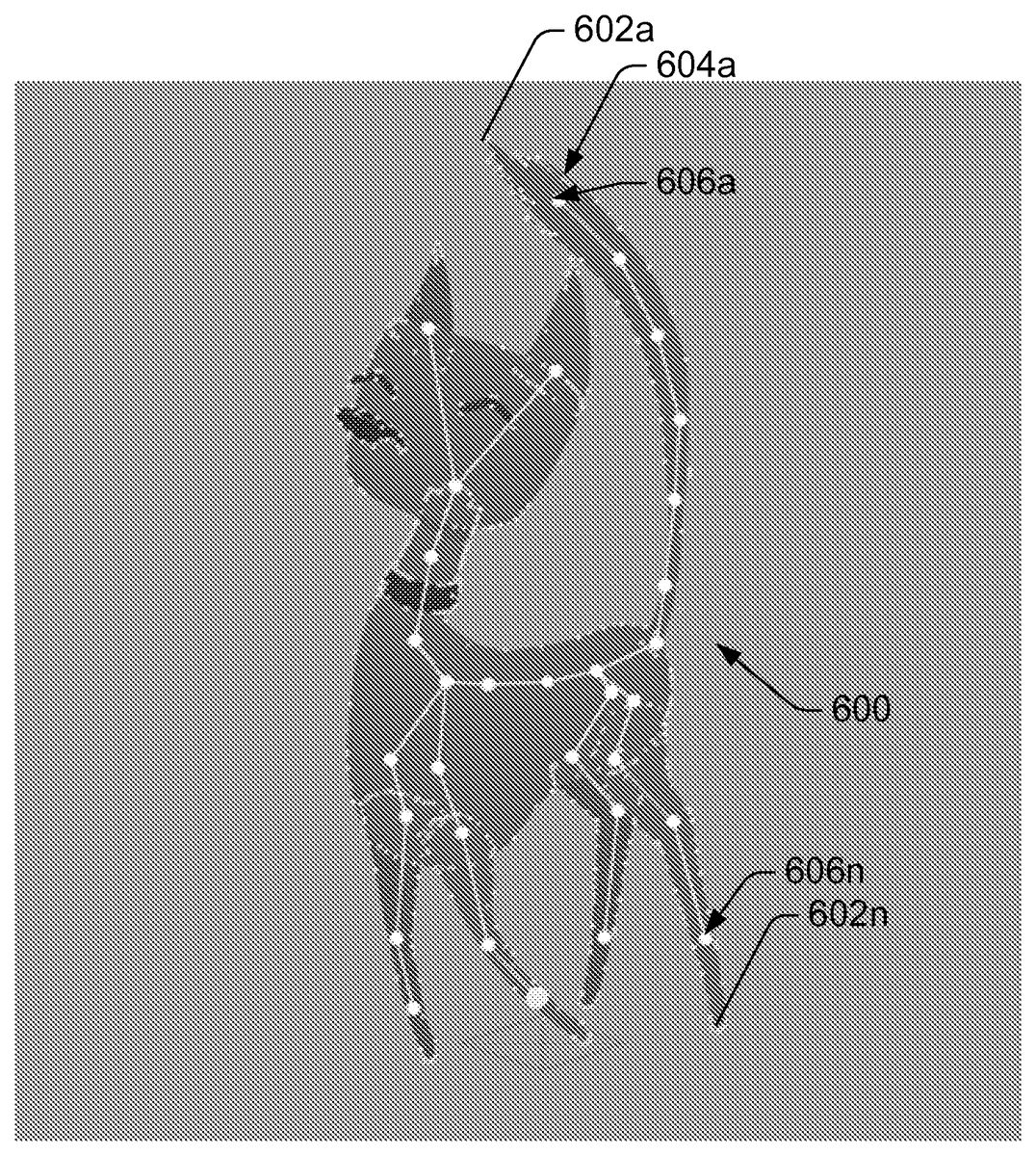
Show inFIG. 5is an exemplary object500having many joints, including joints502a-502n. A shape is formed around each of joints502a-502nin the base position shown. Shown inFIG. 6are points602a-602nthat are formed with respect to each of joints606a-606nto compose a spline. Each of the splines created, such as spline604ais associated with one or more joints, such as joint606a. The splines are combined around shape of the object. As previously explained, once the splines are created, when the joint is moved, the splines associated with that joint are also move to change the position and orientation of the shape of the object.
CONCLUSION
In closing, although the invention has been described in language specific to structural features and/or methodological acts, it is to be understood that the invention defined in the appended claims is not necessarily limited to the specific features or acts described. Rather, the specific features and acts are disclosed as exemplary forms of implementing the claimed invention.
Claims
- A method for generating a computer graphic of a shape to be animated, the shape having at least one joint, wherein the shape changes about the joint, the method comprising: providing, by a computing device, a spline that includes at least two points, each point being defined in a two-dimensional space, the spline being indicative of an outline of the shape in a base position;providing, by the computing device, coordinate information corresponding to positions of the at least two points on the spline that indicate the outline of the shape at predefined positions when the shape is to be changed about the joint with respect to the base position;generating, by the computing device and based at least in part on the provided coordinate information, a new position of the spline to change the shape;and rendering, by the computing device, the spline at the new position to form the outline of the shape associated with the new position, each of the at least two points on the spline being defined in the two-dimensional space represented by (x,y), where: x=t 2 *( P
- x− 2* P
- x+P
- x )+2 t *( P
- x−P
- x )+ P
- x y=t 2 *( P
- y− 2* P
- y+P
- y )+2 t *( P
- y−P
- y )+ P
- y, where t varies between 0 and 1, where (P 2 . x , P 2 . y ) and (P 1 . x , P 1 . y ) are points on the spline, and where (P 3 . x , P 3 . y ) is a point that defines a curvature of the spline.
- The method as recited in claim 1 , further comprising: providing a second spline that includes at least two additional points being defined in the two-dimensional space, the second spline being indicative of a second shape in a second base position;providing additional coordinate information corresponding to a position of the at least two additional points on the second spline corresponding to the second shape at predefined positions that are interpolated based on positions of the first joint and a second joint when the second shape is to be changed about the second joint with respect to the second base position;and generating a new position of the second spline in response to the additional coordinate information that is indicative of the position of the at least two additional points on the second spline that corresponds to the second shape.
- The method as recited in claim 1 , wherein the shape further includes a second joint, and wherein the coordinate information is generated by blending positions of the first joint and the second joint when the shape has changed about the first joint and the second joint with respect to the base position.
- The method as recited in claim 3 , wherein the blending is determined by allocating a first predetermined amount to the position of the spline with respect to the position of the first joint and allocating a second predetermined amount to the position of the spline with respect to the position of the second joint.
- The method as recited in claim 1 , wherein the spline is defined by a two dimensional curve.
- The method as recited in claim 5 , wherein the spline includes a line connecting the at least two points and a third point, the third point controlling a curvature of the line as a function of a distance between the third point and a straight line connecting the at least two points.
- The method as recited in claim 1 , further comprising providing coordinate information by changing a two-dimensional coordinate, an angle, and distance information of the at least two points with respect to the joint.
- The method as recited in claim 1 further comprising: correcting the shape associated with the new position;and rendering the shape associated with the new position.
- A system for rendering a shape comprising: a memory to store a spline that includes at least two points, each of the at least two points being defined in two-dimensional space, the spline being indicative of the shape in a base position, the memory to store coordinate information indicative of a position of the at least two points on the spline that corresponds to the shape at predefined positions when the shape has changed about a joint with respect to the base position;and a processor communicatively coupled to the memory to: generate a new position of the spline based at least in part on the coordinate information;and render the shape associated with the new position to form an outline of the shape, each of the at least two points on the spline being defined in the two-dimensional space represented by (x,y), where: x=t 2 *( P
- x− 2* P
- x+P
- x )+2 t *( P
- x−P
- x )+ P
- x y=t 2 *( P
- y− 2* P
- y+P
- y )+2 t *( P
- y−P
- y )+ P
- y , and where t varies between 0 and 1, where (P 2 . x , P 2 . y ) and (P 1 . x , P 1 . y ) are points on the spline, and where (P 3 . x , P 3 . y ) is a point that defines a curvature of the spline.
- The system as recited in claim 9 , wherein the memory stores a second spline comprising at least two additional points being defined in the two-dimensional space, the second spline being indicative of a second shape in a second base position, and wherein the memory stores additional coordinate information that indicates a position of the at least two additional points on the second spline that corresponds to the second shape at predefined positions that are blended based on positions of the joint and a second joint when the second shape has changed about the second joint with respect to the base position, and wherein the processor is operable to generate a new position of the second spline based at least in part on the additional coordinate information.
- The system as recited in claim 9 , wherein the shape further includes a second joint, and wherein the coordinate information includes a blending based on positions of the joint and the second joint when the shape has changed about the joint and the second joint with respect to the base position.
- The system as recited in claim 11 , wherein the processor is operable to determine the blending by allocating a first predetermined amount to a position of the spline with respect to the position of the joint and allocating a second predetermined amount to a position of the spline with respect to the position of the second joint.
- The system as recited in claim 9 , wherein the memory stores information related to the spline that includes information about a line connecting the at least two points and a third point that in combination with the at least two points defines a curvature of the line as a function of a distance between the third point and a straight line connecting the at least two points.
- The system as recited in claim 9 , wherein the processor is operable to provide the coordinate information by changing a two-dimensional coordinate, an angle, and distance information related to the at least two points with respect to the joint.
- A non-transitory computer storage medium having computer readable instructions that, when executed by a processor, performs operations comprising: providing a plurality of splines, each of the plurality of splines including at least two points, each of the at least two points being defined in two-dimensional space, the plurality of splines being indicative of an outline of a shape in a base position;providing coordinate information that is indicative of a position of the at least two points on each of the plurality of splines, the position of the at least two points corresponding to the outline of the shape at positions in the base position, the coordinate information being generated by blending (a) relative positions of each of the plurality of splines with respect to positions of a first joint with (b) relative positions of each of the plurality of splines with respect to a second joint, when the shape is to be changed about the first joint and the second joint with respect to the base position;generating a new position of the plurality of splines based at least in part on the coordinate information;rendering the plurality of splines at the new position to form the outline of the shape associated with the new position, each of the at least two points on each of the plurality of splines being defined in the two-dimensional space represented by (x,y), where: x=t 2 *( P
- x− 2* P
- x+P
- x )+2 t *( P
- x−P
- x )+ P
- x y=t 2 *( P
- y− 2* P
- y+P
- y )+2 t *( P
- y−P
- y )+ P
- y , and where t varies between 0 and 1, where (P 2 . x , P 2 . y ), (P 1 . x , P 1 . y ) are points on at least one of the plurality of splines, and where (P 3 . x , P 3 . y ) is a point that defines a curvature of at least one of the plurality of splines.
- The non-transitory computer storage medium as recited in claim 15 , wherein the blending is determined by allocating a first predetermined amount to the position of the plurality of splines with respect to the position of the first joint and allocating a second predetermined amount to the position of the plurality of splines with respect to the position of the second joint.
- The non-transitory computer storage medium as recited in claim 15 , wherein each of the plurality of splines include a line connecting the at least two points and a third point, the third point controlling a curvature of the line as a function of a distance between the third point and a straight line connecting the at least two points.
- The non-transitory computer storage medium as recited in claim 15 , wherein the operations further comprise providing coordinate information by changing a two-dimensional coordinate, an angle, and distance information of the at least two points with respect to the first joint or the second joint.
Disclaimer: Data collected from the USPTO and may be malformed, incomplete, and/or otherwise inaccurate.