U.S. Pat. No. 8,388,447
SYSTEMS, METHODS AND TECHNIQUES FOR SAFELY AND EFFECTIVELY COORDINATING VIDEO GAME PLAY CONTESTS BOTH ON AND OFF LINE
AssigneeNintendo Co., Ltd.
Issue DateJune 14, 2011
Illustrative Figure
Abstract
A game involves establishing a Wi-Fi connection for retrieving a template used to create a level for the game. A play test is conducted to determine if the created level of the game can be played. The created game level can be shared with other players and/or submitted as a contest for play and competition judging by other players.
Description
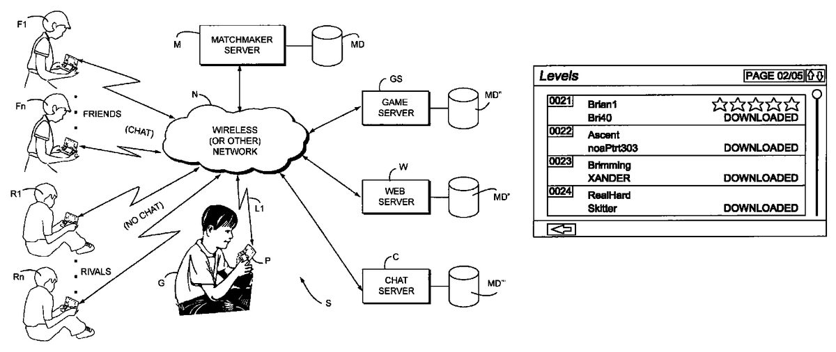
DETAILED DESCRIPTION FIG. 1shows an exemplary illustrative non-limiting implementation of a networked gaming system S. In the exemplary illustrative non-limiting system S, a gamer G plays a video game or runs another networked application on a networked gaming or other platform P. Platform P can be for example a Nintendo DS portable handheld wireless gaming platform, the Nintendo Revolution platform, or any other gaming or other networked platform capable of playing a game or providing other application(s). Gaming platform P connects via a wireless or wired link L1to a network N. Network N can be for example the Internet, an 802.11 wireless “WI-FI” network in the ad hoc or infrastructure mode, a cellular telephone network, a local area network, a wide area network, or any other network capable of communicating information between devices. Platform P uses the network to allow gamer G to play multi-player games against other garners F1. . . FN, R1. . . RN who may be remotely located. These other garners can be located across the room, across town or across the world. As further shown inFIG. 1, servers such as a matchmaker server M, a game server GS, a web server W and a chat server C are coupled directly or indirectly to network N. Gaming platforms P, F1. . . FN, R1. . . RN can communicate with these various servers M, GS and W via network N. In the exemplary illustrative implementation, each of servers includes a mass storage device MD for securely storing information concerning the identities and other information about users of gaming platforms P, F1. . . FN, R1. . . RN. Matchmaker server M (which may be a conventional server and associated software provided by Game Spy) matches up video game players based on skill level, previous game statistics, ...
DETAILED DESCRIPTION
FIG. 1shows an exemplary illustrative non-limiting implementation of a networked gaming system S. In the exemplary illustrative non-limiting system S, a gamer G plays a video game or runs another networked application on a networked gaming or other platform P. Platform P can be for example a Nintendo DS portable handheld wireless gaming platform, the Nintendo Revolution platform, or any other gaming or other networked platform capable of playing a game or providing other application(s).
Gaming platform P connects via a wireless or wired link L1to a network N. Network N can be for example the Internet, an 802.11 wireless “WI-FI” network in the ad hoc or infrastructure mode, a cellular telephone network, a local area network, a wide area network, or any other network capable of communicating information between devices. Platform P uses the network to allow gamer G to play multi-player games against other garners F1. . . FN, R1. . . RN who may be remotely located. These other garners can be located across the room, across town or across the world.
As further shown inFIG. 1, servers such as a matchmaker server M, a game server GS, a web server W and a chat server C are coupled directly or indirectly to network N. Gaming platforms P, F1. . . FN, R1. . . RN can communicate with these various servers M, GS and W via network N. In the exemplary illustrative implementation, each of servers includes a mass storage device MD for securely storing information concerning the identities and other information about users of gaming platforms P, F1. . . FN, R1. . . RN.
Matchmaker server M (which may be a conventional server and associated software provided by Game Spy) matches up video game players based on skill level, previous game statistics, geographical location, or any of a variety of other characteristics, and may keep track of player status information such as which players are online and which ones are not, which online players are already engaged in playing a game and which ones are waiting to play, which “ready room” each player inhabits waiting to play a game with others in the same virtual “ready room”, and other functionality.
Web server W (which may be coupled to matchmaker server M) can allow gamers to access certain types of status information about other players via a conventional web browser launched on gaming platforms P or other appliances having embedded or other web browser functionality.
Game Server GS may provide game downloads or other information downloads.
Chat server C may provide facilities to allow certain garners to “chat” (communicate) via text messaging, voice messaging, video messaging, or other messaging.
In the exemplary illustrative non-limiting system S shown, the gamer G operating gaming platform P can play a multiplayer game over network N with (at least) two different categories of other gamers: “Friends”F1. . . FN or “Rivals” R1. . . RN. In the exemplary illustrative non-limiting example, a “Friend” is someone the gamer G knows personally. A “Rival” is someone the gamer G does not know personally but perhaps has “met” online (e.g., by being matched up by matchmaker server M with that person to play a game previously) and which the gamer G wants to keep track of for future game play.
In the exemplary illustrative non-limiting implementation, system S maintains different lists or rosters for Friends and Rivals, and handles each of those lists or rosters differently while allowing gamer G to selectively play games against Friends, Rivals or both. Additional or different categories of opponents can be provided if desired.
Exemplary Illustrative Non-limiting Gaming Platform
Referring toFIG. 2A, a game device P of one exemplary illustrative non-limiting implementation includes a first liquid crystal display (LCD)12and a second LCD14. The LCD12and the LCD14are provided on a housing16so as to be arranged in a predetermined position. In this implementation, the housing16consists of an upper housing16aand a lower housing16b, and the LCD12is provided on the upper housing16awhile the LCD14is provided on the lower housing16b. Accordingly, the LCD12and the LCD14are closely arranged so as to be longitudinally (vertically) parallel with each other.
It is noted that although the LCD is used as a display in this implementation, an EL (Electro-Luminescence) display or a plasma display may be used in place of the LCD. Alternatively, a CRT display may be used for game consoles, arcade video game machines, etc.
As can be understood fromFIG. 2A, the upper housing16ahas a planar shape a little larger than a planar shape of the LCD12, and has an opening formed so as to expose a display surface of the LCD12from one main surface thereof. The lower housing16bhas a planar shape horizontally longer than the upper housing16a, and has an opening formed so as to expose a display surface of the LCD14at an approximately center of the horizontal direction. Furthermore, the lower housing16bis provided with a sound hole18and an operating switch20(20a,20b,20c,20d,20e,20L and20R).
The upper housing16aand the lower housing16bare rotatably connected at a lower side (lower edge) of the upper housing16aand a part of an upper side (upper edge) of the lower housing16b. Accordingly, in a case of not playing a game, for example, if the upper housing16ais rotatably folded such that the display surface of the LCD12and the display surface of the LCD14are face to face with each other, it is possible to prevent the display surface of the LCD12and the display surface of the LCD14from being damaged. The upper housing16aand the lower housing16bare not necessarily rotatably connected with each other, and may alternatively be provided integrally (fixedly) to form the housing16.
The operating switch20includes a direction instructing switch (cross switch)20a, a start switch20b, a select switch20c, an action switch (A button)20d, an action switch (B button)20e, an action switch (L button)20L, and an action switch (R button)20R. The switches20a,20band20care placed at the left of the LCD14on the one main surface of the lower housing16b. The switches20dand20eare placed at the right of the LCD14on the one main surface of the lower housing16b. Switches20L and20R are placed in a part of an upper edge (top surface) of the lower housing16band lie on each side of the connected portion with the upper housing16a.
The direction instructing switch20afunctions as a digital joystick, and is used for instructing a moving direction of a player character (or player object) to be operated by a player, instructing a moving direction of a cursor, and so forth by operating any one of four depression portions. The start switch20bis formed by a push button, and is used for starting (restarting) a game, temporarily stopping (pausing) a game, and so forth. The select switch20cis formed by the push button, and used for a game mode selection, etc.
The action switch20d(that is, the A button) is formed by the push button, and allows the player character to perform an action that is game specific. For example, it may be used for instructing character movement direction, such as hitting (punching), throwing, holding (obtaining), riding, jumping, etc. For example, in an action game, it is possible to apply an instruction of jumping, punching, moving arms, etc. In a role-playing game (RPG) or a simulation RPG, it is possible to apply an instruction of obtaining an item, selecting and determining acts or commands, etc. The action switch20e(that is, the B button) is provided by a push button, and is used for changing a game mode selected by the select switch20c, canceling an action determined by the A button20d, and so forth.
The action switch (left depression button)20L and the action switch (right depression button)20R are formed by a push button. The left depression button (L button)20L and the right depression button (R button)20R can perform the same operation as the A button20dand the B button20e, and also function as a subsidiary of the A button20dand the B button20e.
A touch panel22is provided on a top surface of the LCD14. As the touch panel22, any type of a resistance film system, an optical system (infrared rays system) or an electrostatic capacitive coupling system, for example, can be used. In response to an operation of depressing, stroking or touching with a stick24, a pen (stylus pen), or a finger (hereinafter, referred to as “stick24, etc.”) on a top surface (detection surface) of the touch panel22, the touch panel22detects coordinates of operating position of the stick24, etc. and outputs coordinate data corresponding to the detected coordinates.
According to this implementation, the exemplary non-limiting resolution of the display surface of the LCD14is 256 dots×192 dots, and a detection accuracy of a detection surface of the touch panel22is also rendered 256 dots×192 dots in correspondence to the resolution of the display surface (this is the same or approximately the same as for the LCD12). Detection accuracy of the detection surface of the touch panel22, however, may be lower than the resolution of the display surface of the LCD14, or higher than it. In the detected coordinates of the touch panel22, a point of origin (0, 0) is on an upper left corner, a right horizontal direction is an X-axis normal direction and a downward vertical direction is a Y-axis normal direction (the same applies to the coordinate system of the LCD14(12)). A three-dimensional game space often has X and Y coordinates on the horizontal plane and a Z axis in a vertical direction.
It is possible to display different game images (game screens) on the LCD12and the LCD14. This allows the player to point at (specify) or make active (move) character images displayed on the screen of the LCD14, such as player characters, enemy characters, item characters, text information and icons, or select a command, by operating the touch panel22with the stick24, etc. This also makes it possible to change an orientation of a virtual camera (viewpoint) provided in the three-dimensional game space or scroll through a game screen (the screen is displayed in a state of being gradually moved).
As stated above, the game device10has the LCD12and the LCD14as a display portion of two screens, and by providing the touch panel22on an upper surface of any one of them (LCD14in the first embodiment), the game device10has the two screens (LCD12,14) and the two operating portions (20,22).
Additionally, in this implementation, the stick24can be inserted into a housing portion (housing slot)26provided in proximity to a side surface (right side surface) of the upper housing16a, for example, and taken out therefrom as necessary. In a case of providing no stick24, it is not necessary to provide the housing portion26.
The game device10further includes a memory card (or game cartridge)28. The memory card28is detachable, and inserted into a loading slot30provided on a rear surface or a lower edge (bottom surface) of the lower housing16b. Although omitted inFIG. 2A, a connector46(seeFIG. 2B) is provided at a depth portion of the loading slot30for connecting a connector (not shown) provided at an end portion of the memory card28in the loading direction. When the memory card28is loaded into the loading slot30, the connectors are connected with each other, and therefore, the memory card28is accessible by a CPU core42(seeFIG. 2B) of the game device10.
A speaker32(seeFIG. 2B) is provided at a position corresponding to the sound hole18inside the lower housing16b. A battery accommodating box is provided on a rear surface of the lower housing16b, and a power switch, a volume switch, an external expansion connector, an earphone jack, etc. are provided on a bottom surface of the lower housing16b.
FIG. 2Bis a block diagram showing an exemplary illustrative non-limiting electric configuration of the game device10. Referring toFIG. 2B, the game device10includes an electronic circuit board40, and on the electronic circuit board40, a circuit component such as a CPU core42, etc. is mounted. The CPU core42is connected to the connector46via a bus44, and is connected with a RAM48, a first graphics processing unit (GPU)50, a second GPU52, an input-output interface circuit (hereinafter, referred to as “I/F circuit”)54, and an LCD controller60.
The connector46is detachably connected with the memory card28as described above. The memory card28includes a ROM28aand a RAM28b. The ROM28aand the RAM28bare connected with each other via a bus and also connected with a connector (not shown) to be connected with the connector46. Accordingly, the CPU core42gains access to the ROM28aand the RAM28bas described above.
The ROM28astores in advance a game program for a virtual game to be executed by the game device10. ROM28amay also store image data (character image, background image, item image, icon (button) image, message image, etc.), data representing sounds or music used to accompany the game (sound data), etc. The RAM (backup RAM)28bstores (saves) proceeding data and result data of the game.
The RAM48is used as a buffer memory or a working memory. The CPU core42loads the game program, the image data, the sound data, etc. stored in the ROM28aof the memory card28into the RAM48, and executes the loaded game program. The CPU core42executes a game process while storing in the RAM48data (game data and flag data) temporarily generated in correspondence with progress of the game.
The game program, the image data, the sound data, etc. are loaded from the ROM28aentirely at a time, or partially and sequentially so as to be stored (loaded) into the RAM48.
Each of the GPU50and the GPU52forms a part of a rendering means. They may be provided by, for example, a single chip ASIC. GPU50,52receive graphics commands from the CPU core42to generate game image data according to the graphics command. The CPU core42provides each of the GPU50and the GPU52with an image generating program (included in the game program) used to generate the game image data in addition to the graphics command.
GPU50is connected with a first video RAM (hereinafter, referred to as “VRAM”)56. GPU52is connected with a second VRAM58. The GPU50and the GPU52obtain data required for the GPU50and the GPU52to execute the graphics command (image data: character data, texture data, etc.) by access to a first VRAM56and a second VRAM58, respectively. The CPU core42writes the image data required for graphics drawing into the first VRAM56and the second VRAM58via the GPU50and the GPU52. The GPU50accesses the VRAM56to generate the game image data for graphics drawing. GPU52accesses the VRAM58to generate the game image data for graphics drawing.
The VRAM56and the VRAM58are connected to the LCD controller60. The LCD controller60includes a register62. Register62consists of, for example, one bit. Register62stores a value of “0” or “1” (data value) according to an instruction of the CPU core42. When the data value of the register62is “0”, the LCD controller60outputs the game image data generated by the GPU50to the LCD12, and outputs the game image data generated by the GPU52to the LCD14. When the data value of the register62is “1”, the LCD controller60outputs the game image data generated by the GPU50to the LCD14, and outputs the game image data generated by the GPU52to the LCD12.
The LCD controller60reads out game image data directly from the VRAM56and the VRAM58, and reads out game image data from the VRAM56and the VRAM58via the GPU50and the GPU52.
The I/F circuit54is connected with the operating switch20, the touch panel22and the speaker32. Operating switch20is the above-described switches20a,20b,20c,20d,20e,20L and20R. In response to an operation of the operating switch20, a corresponding operation signal (operation data) is input to the CPU core42via the I/F circuit54. The coordinates position data from the touch panel22is input to the CPU core42via the I/F circuit54. The CPU core42reads-out the sound data necessary for the game such as a game music (BGM), a sound effect or voices of a game character (onomatopoeic sound), etc. from the RAM48, and outputs it from the speaker32via the I/F circuit54.
FIG. 2Bfurther shows a “Wi-Fi” wireless adapter33and associated antenna35. Wi-Fi wireless adapter33comprises a transceiver (transmitter and receiver) that allows gaming platform P to communicate wirelessly via network N. Wi-Fi wireless adapter33may comprise for example a baseband system, modulator and amplifiers compliant with the conventional 802.11 standard. Wi-Fi wireless adapter33wirelessly receives information transmitted over RF from other devices, and wirelessly sends information to other devices. Other wired or wireless technology (e.g., Ethernet, WAN, Bluetooth, etc.) could be substituted. Wireless adapter33allows gaming platform P to communicate with other gaming platforms or other devices in the same room or vicinity and/or with more remote devices. Network N could be a very localized network such as a 20-meter range WI-FI ad hoc connection, or it could be a worldwide network such as the Internet, or any other wired or wireless network you can think of.
Example Level Construction
FIG. 3shows an exemplary non-limiting implementation of a playground game flow for creating game levels and submitting a created game level for a contest mode. These actions may be taken offline except for the downloading of game templates and uploading of a created game level for a contest. In step S1902, the user selects the construction zone and in step S1904contest is selected so that in step S1906a suitable contest template is obtained for the user to create contest levels and view the created contest levels.
More particularly, in step S1906, selection of the create contest levels will first cause the user to be connected to network N in step S1908to get the latest contest template before starting to create any contest levels. Thereafter in step S1914the user is able to create or edit his own contest levels.
If in step S1906the view contest levels selection is made then contest levels are displayed in step S1910. The status of the displayed contest levels is given as current, expired or winner. A selected contest level can be played, edited or deleted in step S1912. If the selected contest level is to be edited and has not expired the flow chart proceeds to step S1914for editing of the selected and current contest level.
After the contest levels have been created or edited in step S1914it is determined in a play test whether the contest level is playable. Levels can be constructed as described for example in U.S. patent application Ser. No. 13/160,305, entitled “Method and Apparatus for Constructing Virtual Sloped Landscapes in Computer Graphics and Animation,” filed on date even herewith; U.S. patent application Ser. No. 13/160,372, entitled “Real-Time Terrain Animation Selection,” filed on date even herewith; U.S. patent application Ser. No. 13/156,762, filed Jun. 9, 2011, entitled “Rivet Mechanisms”; and U.S. provisional application No. 61/497,011, entitled “Methods and/or Systems for Designing Virtual Environments”filed on date even herewith; all incorporated by reference. If the user successfully passes the play test of the level, then in step S1916the user can retry the level, edit the level, submit the level, or exit. If the submit level button is activated in step S1916the user is connected to Nintendo WFC to upload the contest level in step S1918.
In step S1920it is determined whether the contest level has expired. If the answer is yes, the contest level ends and the user is instructed in step S1922to download the latest contest template and create a new level to submit before contest submission ends. If the answer in step S1920is no, then a further determination is made as to whether the contest level for a current contest has already been submitted in step S1924. If the answer is no, then the flow chart ends by submitting or uploading the user's created contest level in step S1928. If the answer in step S1924is yes, then the user is notified in step S1926that the contest level has already been submitted and only one contest level can be submitted per contest. The user is also instructed to judge other contest levels to help determine contest winners and to check back later to see if the user's contest level is a winner.
Example Online Contesting
FIG. 4shows a playground game flow for a contest mode which is conducted online. In step S2002if the construction zone is selected and in step S2004if the contest level is selected, then the latest information about the latest contest template is provided to the user in step S2006.
If the view contest levels is selected in step S2006then in step S2008the user is connected to the Nintendo WFC.
In step S2010the user submits a contest level, gets the latest contest template or downloads contest levels. In step S2012it is checked if the user has the latest contest template and downloads it if the user does not. If the user downloads contest levels, then in step S2014certain information is provided concerning the contest level including the contest title, description and end date.
In step S2016the current contest levels are randomly displayed and in step S2028the top ten levels of the past contests are displayed.
If the user submits a contest level in step S2010, then it is determined in step S2018whether the contest level is expired. If the contest level is expired, then in step S2020notification of that fact is provided to the user. If the contest level has not expired, then in step S2022the user is asked whether the contest level for the current contest has been submitted. If the answer is no, then in step S2026the user's created contest level is submitted. If the contest level has been previously submitted, however, then in step S2024the user is notified that the level has already been submitted for the contest and only one level can be submitted per contest. The user is also instructed to judge other contest levels to help determine contest winners and to check back later to see if the level is a winner.
FIG. 5is a screen shot of a contest level named “Brimming” that was created by Xander. The number of downloads and the high score for the Brimming level are provided together with an identification of the template used (000003) and other identifiers, i.e., normal and small. The screen shot includes activation buttons for delete and play of the level.
FIG. 6is a screen shot of downloaded levels.FIGS. 7 and 8show screen shots of the Challenge Center which respectively provide Challenge Updates and Construction Zone News.FIGS. 9 and 10are screen shots showing the submission of levels to Friends & Favorites. More particularly,FIG. 9shows the listing of Friends & Favorites that can be used for sharing created contest levels, andFIG. 10shows a screen shot of contest level judged by Skitter.
While the technology herein has been described in connection with exemplary illustrative non-limiting implementations, the invention is not to be limited by the disclosure. For example, while exemplary illustrative non-limiting implementations have been described in connection with portable wireless video game platforms, any sort of appliance capable of being connected to a wired and/or wireless network may be used. The invention is intended to be defined by the claims and to cover all corresponding and equivalent arrangements whether or not specifically disclosed herein.
Claims
- A computer implemented method for creating a game, comprising: establishing a wireless connection for downloading a game template configured to allow play of a basic game to a user's personal device;allowing the user to create a new game by creating new game levels in the basic game using said downloaded template;providing for the user to view and/or edit the created new game;conducting a play test to determine playability of the created new game;and sharing the created new game with other users.
- The method according to claim 1 , wherein the created new game comprises at least one created level that is shared for play by other players.
- The method according to claim 1 , wherein the created new game complies with special content templates that the user must use to submit the created new game as a contest level for play and judging by other players.
- The method according to claim 1 , further comprising wirelessly delivering a tutorial on how to build game levels.
- The method according to claim 4 , wherein the tutorial includes practical hands on experience in building game levels.
- A computer implemented method for creating a new level of a basic game, said method comprising: establishing a wireless connection for downloading a template for creating the new level of the basic game;allowing a user to create the new level of the basic game by using said downloaded template;and providing for the user to view and/or edit the created new level of the basic game.
- The method according to claim 6 , wherein the created new level complies with special content templates that the user must use to submit the created new level as a contest level for play by others.
- A game system which in addition to game play allows a user to create a new level of a basic game, said system comprising: at least one processor programmed for: a) establishing a Wi-Fi connection for downloading a game template configured to allow play of the basic game;b) allowing the user to create the new level of the basic game by using said downloaded template;c) providing for the user to view and/or edit the created new level of the basic game;and d) conducting a play test to determine if the created new level of the basic game can be played;and a server for storing said game template that is wirelessly accessible by said at least one processor.
- The game system as claimed in claim 8 , said server further storing a tutorial on how to build game levels for download to said at least one processor.
- The game system as claimed in claim 8 , wherein the created level complies with special content templates that the user must use before uploading the created level to said server as a contest level for play and judging by other players.
Disclaimer: Data collected from the USPTO and may be malformed, incomplete, and/or otherwise inaccurate.