U.S. Pat. No. 8,376,850
GAME CONTROLLER AND CONTROLLING METHOD THEREOF
AssigneeHon Hai Precision Industry Co., Ltd.
Issue DateAugust 19, 2009
Illustrative Figure
Abstract
A game controller includes a housing, a number of press sensors and touch sensors, and a main circuit embedded in the housing powered by a battery. The main circuit includes a collecting module, a comparing module and a controlling module. The press sensors detects pressure from the housing and outputting a number of pressure signals. The touch sensors detects a plurality of touch signals. The collecting module collects and combines the pressure signals and the touch signals into a first positioning signal and a second positioning signal correspondingly. The comparing module predetermines a number of preset signal values and a number of preset pitches correspondingly and compares the first and second positioning signals with the preset signal values. The controlling module triggers one of the preset pitches when the first positioning signal and the second positioning signal are equal to the preset signal values.
Description
DETAILED DESCRIPTION Referring toFIGS. 1 and 2, a game controller100for controlling a pitch direction of a baseball game is shown. In this embodiment, the game controller100is a remote controller and communicates with a game console (not shown) via infrared ray. A current pitch of the baseball can be shown on a display (not shown) connected to the game console. The game controller100includes a housing10, a battery20, and a main circuit30embedded in the housing10. The housing10is a baseball-shaped configuration. The housing10includes a first region11and a second region12connected to the first region11. In this embodiment, the first region11is made of leather material, while the second region12is a seam and made of elastic material. The housing10further includes a strap13fixed to the first region11and hung on a user's wrist. The battery20is electrically connected to the main circuit30and configured for providing electrical power to the main circuit30. In this embodiment, the battery20is a lithium cell. Referring toFIG. 3, the game controller100further includes a number of press sensors31and a number of touch sensors32connected to the main circuit30. The main circuit30includes a collecting module33, a comparing module34, and a controlling module35. In this embodiment, the collecting module33, the comparing module34, the controlling module35are integrated in the main circuit30, and the press sensors31and the touch sensors32are received in the housing10. The press sensors31are disposed under the second region12independently and assigned with a unique first identifier, correspondingly. In this embodiment, the press sensors31are assigned first identifiers numerically according to the position of the press sensors31relative to the strap13and the first identifiers are stored in a memory (not shown). A first analog-to-digital converter36a(A/D converter) is connected between the press sensors31and the collecting module33. The press sensors31are configured for transmitting a number of pressure signals to the first A/D converter36aaccording to the order of the first identifiers when the press sensors31are ...
DETAILED DESCRIPTION
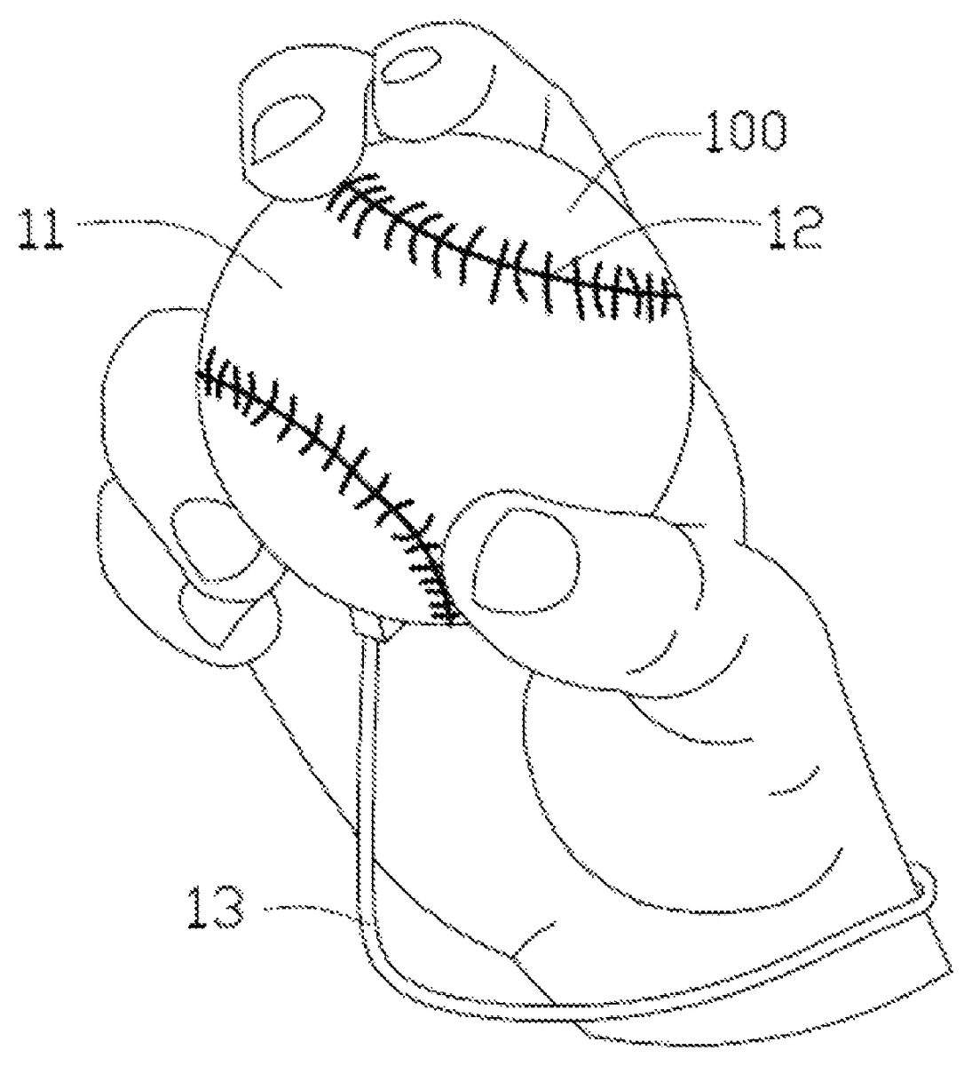
Referring toFIGS. 1 and 2, a game controller100for controlling a pitch direction of a baseball game is shown. In this embodiment, the game controller100is a remote controller and communicates with a game console (not shown) via infrared ray. A current pitch of the baseball can be shown on a display (not shown) connected to the game console. The game controller100includes a housing10, a battery20, and a main circuit30embedded in the housing10.
The housing10is a baseball-shaped configuration. The housing10includes a first region11and a second region12connected to the first region11. In this embodiment, the first region11is made of leather material, while the second region12is a seam and made of elastic material. The housing10further includes a strap13fixed to the first region11and hung on a user's wrist.
The battery20is electrically connected to the main circuit30and configured for providing electrical power to the main circuit30. In this embodiment, the battery20is a lithium cell.
Referring toFIG. 3, the game controller100further includes a number of press sensors31and a number of touch sensors32connected to the main circuit30. The main circuit30includes a collecting module33, a comparing module34, and a controlling module35. In this embodiment, the collecting module33, the comparing module34, the controlling module35are integrated in the main circuit30, and the press sensors31and the touch sensors32are received in the housing10.
The press sensors31are disposed under the second region12independently and assigned with a unique first identifier, correspondingly. In this embodiment, the press sensors31are assigned first identifiers numerically according to the position of the press sensors31relative to the strap13and the first identifiers are stored in a memory (not shown).
A first analog-to-digital converter36a(A/D converter) is connected between the press sensors31and the collecting module33. The press sensors31are configured for transmitting a number of pressure signals to the first A/D converter36aaccording to the order of the first identifiers when the press sensors31are pressed correspondingly. The first A/D converter36ais configured for converting each of the pressure signals into a digital signal and transmitting the digital signal to the collecting module33one by one. In this embodiment, the first A/D converter36aoutputs a signal “1” when one of the press sensor31senses the pressure, otherwise outputs a signal “0” when the press sensor31does not sense any pressure.
The touch sensors32are embedded under the first region11. Each touch sensor32is assigned a second identifier numerically according to the position of the touch sensors32relative to the strap13. A second A/D converter36bis connected between the touch sensor32and the collecting module33. Each touch sensor32is configured for transmitting a touched signal to the second A/D converter36baccording to the order of the second identifier. The second A/D converter36bis configured for converting the touch signals into a digital signal and transmitting the digital signal to the collecting module33. In this embodiment, the touch sensors32are capacitance type sensors. When the touch sensor32is touched, the capacitance changes and the second A/D converter36boutputs the digital signal according to the changed capacitance. In this embodiment, the second A/D converter36boutputs a signal “1” when the capacitance of the touch sensor32changes, otherwise outputs a signal “0” when the capacitance of the touch sensor32does not change.
The collecting module33is configured for collecting the digital signals from the first and second A/D converters36aand36b, respectively, and combining the digital signals from the first A/D converter36ainto a first positioning signal and the digital signals from the second A/D converter36binto a second positioning signal. In this embodiment, the first positioning signal and the second positioning signal are composed of a number of signals “1” and signals “0”, respectively, and the order of the signals “1” and signals “0” arranged is the same as the order of the first identifiers and the second identifiers correspondingly.
The comparing module34predetermines a number of preset signal values and a number of preset pitches corresponding to the preset signal values. The comparing module34is configured for comparing the first positioning signal and the second positioning signal with the preset signal values one by one.
The controlling module35is configured for controlling the game console to select one of the preset pitches as a current pitch according to the preset signal values, and display the current pitch on the display. In this embodiment, the controlling module35is connected to the game console that can display the pitch on the display. When a combination of the first positioning signal and the second positioning signal does not equal to the preset signal values, the controlling module35controls the comparing module34to continue comparing the first positioning signal and the second positioning signal with the rest of the preset signal values.
In order to be more realistic, the main circuit30further includes a naming program module37for renaming the current pitch according to user input. The naming program module37is connected to the collecting module33. When the collecting module33collects one of the first positioning signal and one of the second positioning signal, the game console shows a command for editing the name of a current pitch or not. The naming program module37can store the new name of the current pitch when the original name is edited.
Referring back toFIG. 2, in order to motivate the feeling of third dimension, the game controller100further includes an acceleration transducer38embedded in the housing10and a gyroscope39disposed in the center of the housing10. The acceleration transducer38calculates an acceleration of the game controller100according to a composition of forces applied on the housing10and driving the baseball in the game with such acceleration. The gyroscope39senses a rotary speed of the game controller100and representing the rotary movement of the baseball with such rotary speed.
When in use, the game controller100is held in one's hand as shown inFIG. 1such that the first region11rest in the palm, and the second region is pressed by the fingers, then the game controller100is thrown out. At this time, the press sensor31outputs the pressure signals according to where the fingers locate and the touch sensors32outputs the touch signals according to where the user's palm held. Because, the strap13is hung on the wrist to limit how far the game controller can be thrown (pitch), thereby preventing damages the game controller100. The collecting module33collects the pressure signals and the touch signals and achieves a first positioning signal and a second positioning signal, then, the comparing module34can confirm a preset pitch as a current pitch when both the first positioning signal and the second positioning signal are equal to the preset signal values. The controlling module35controls the game console to trigger one of the preset pitches to be started as a current pitch when both of the first positioning signal and the second positioning signal are equal to the preset signal values, and then the current pitch displayed on the display according to the preset pitch with the acceleration and the rotary speed of the game controller100.
Referring toFIG. 4, a controlling method for the game controller100with a number of press sensors31and a number of touch sensors32includes the following steps.
In step S601, the press sensors31detect pressure and outputs a plurality of pressure signals, and the touch sensors32detect a plurality of touch signals. The press sensors31are assigned with a plurality of first identifiers, the touch sensors32are assigned with a plurality of second identifiers, respectively. The first A/D converter is connected to the press sensors31, and the method further comprises step S603: the press sensors31transmit the pressure signals to the first A/D converter36aaccording to the order of the first identifiers correspondingly, and the first A/D converter36aconverts each of the pressure signals into a digital signal. The second A/D converter36bis connected to the touch sensor, and the method further comprises step S605: the touch sensors32transmit the touch signals to the second A/D converter36baccording to the order of the second identifiers correspondingly, and the second A/D converter36bconverts each of the touch signals into a digital signal.
In step S607, the pressure signals from the press sensors31and the touch signals from the touch sensors32are collected correspondingly. And the pressure signals are combined into a first positioning signal and the touch signals are combined into a second positioning signal.
In step S609, the number of preset signal values and the number of the preset pitches corresponding to the preset signal values are predetermined. Then the first positioning signal and the second positioning signal are compared with the preset signal values one by one.
In step S611, when each of the first positioning signal and the second positioning signal are equal to the preset signal values, one of the preset pitches is triggered to be started. Meanwhile, the preset pitch is controlled to be displayed on the display as a current pitch when the preset pitch is started. When one of the first positioning signal and the second positioning signal is not equal to the preset signal values, the first positioning signal and the second positioning signal are continued to be compare with the preset signal values.
It will be understood that the above particular embodiments and methods are shown and described by way of illustration only. The principles and the features of the present invention may be employed in various and numerous embodiments thereof without departing from the scope of the invention as claimed. The above-described embodiments illustrate the scope of the invention but do not restrict the scope of the invention.
Claims
- A game controller for controlling a game console, comprising: a housing comprising a first region and a second region;a main circuit embedded in the housing and powered by a battery;and a plurality of press sensors spreading under the second region and configured for detecting pressure from the second region and outputting a plurality of pressure signals;a plurality of touch sensors embedded under the first region and configured for detecting a plurality of touch signals from the first region;a collecting module configured for collecting the pressure signals and the touch signals from the press sensors and the touch sensors correspondingly, and combining the pressure signals into a first positioning signal and the touch signals into a second positioning signal;a comparing module predetermining a plurality of preset signal values and a plurality of preset pitches corresponding to the preset signal values and configured for comparing the first positioning signal and the second positioning signal with the preset signal values one by one;and a controlling module configured for controlling the game console to trigger one of the preset pitches to be started when each of the first positioning signal and the second positioning signal are equal to the preset signal values.
- The game controller in claim 1 , wherein the first region is made of leather material, while the second region is a seam and made of elastic material.
- The game controller in claim 1 , wherein the housing comprises a strap fixed to the first region and configured for being hung on a user's wrist for limiting the thrown pitch distance of the game controller.
- The game controller in claim 3 , wherein the press sensors are assigned with a plurality of first identifiers, the touch sensors are assigned with a plurality of second identifiers, respectively.
- The game controller in claim 4 , wherein a first analog-to-digital converter (A/D converter) is connected between the press sensors and the collecting module, the press sensors are configured for transmitting the pressure signals to the first A/D converter according to the order of the first identifiers correspondingly, and the first A/D converter is configured for converting each of the pressure signals into a digital signal and transmitting the digital signals to the collecting module one by one.
- The game controller in claim 4 , wherein a second analog-to-digital converter (A/D converter) is connected between the touch sensor and the collecting module, the touch sensors are configured for transmitting the touch signals to the second A/D converter according to the order of the second identifiers correspondingly, and the second A/D converter is configured for converting each of the touch signals into a digital signal and transmitting the digital signals to the collecting module.
- The game controller in claim 5 , wherein the first A/D converter outputs a signal “ 1 ” when one of the press sensor senses the pressure, otherwise outputs a signal “ 0 ” when the press sensor does not sense any pressure, and the first positioning signal is composed of a number of signals “ 1 ” and signals “ 0 ”.
- The game controller in claim 6 , wherein the touch sensors are capacitance type sensors.
- The game controller in claim 8 , wherein the second A/D converter outputs a signal “ 1 ” when the capacitance of the touch sensor changes, otherwise outputs a signal “ 0 ” when the capacitance of the touch sensor does not change, and the second positioning signal is composed of a number of signals “ 1 ” and signals “ 0 ”.
- The game controller in claim 1 , wherein when one of the first positioning signal and the second positioning signal is not equal to the preset signal values, the comparing module continues to compare the first positioning signal and the second positioning signal with the rest of the preset signal values.
- The game controller in claim 1 , wherein the main circuit further comprises a naming program module for renaming the preset pitch according to user input.
- The game controller in claim 1 , further comprising an acceleration transducer embedded in the housing and a gyroscope disposed in the center of the housing.
- The game controller in claim 12 , wherein the acceleration transducer calculates an acceleration of the game controller according to a composition of forces applied on the housing and driving the baseball in the game with such acceleration.
- The game controller in claim 12 , wherein the gyroscope senses a rotary speed of the game controller.
- The game controller in claim 1 , being baseball-shaped.
- A controlling method for a game controller with a number of press sensors and a number of touch sensors comprising the following steps: detecting pressure via the press sensors and outputting a plurality of pressure signals, and detecting a plurality of touch signals via the touch sensors;collecting the pressure signals from the press sensors and the touch signals from the touch sensors correspondingly, and combining the pressure signals into a first positioning signal and the touch signals into a second positioning signal;predetermining a plurality of preset signal values and a plurality of preset pitches corresponding to the preset signal values and comparing the first positioning signal and the second positioning signal with the preset signal values one by one;triggering one of the preset pitches to be started when each of the first positioning signal and the second positioning signal are equal to the preset signal values.
- The controlling method in claim 16 , wherein the press sensors are assigned with a plurality of first identifiers, the touch sensors are assigned with a plurality of second identifiers, respectively.
- The controlling method in claim 17 , wherein a first analog-to-digital converter (A/D converter) is connected to the press sensors, and the method further comprises: the press sensors transmitting the pressure signals to the first A/D converter according to the order of the first identifiers correspondingly, and the first A/D converter converting each of the pressure signals into a digital signal.
- The controlling method in claim 17 , wherein a second A/D converter is connected to the touch sensor, and the method further comprises: the touch sensors transmitting the touch signals to the second A/D converter according to the order of the second identifiers correspondingly, and the second A/D converter converting each of the touch signals into a digital signal.
- The controlling method in claim 16 , wherein when one of the first positioning signal and the second positioning signal is not equal to the preset signal values, the method further comprises: continuing to compare the first positioning signal and the second positioning signal with the rest of the preset signal values.
Disclaimer: Data collected from the USPTO and may be malformed, incomplete, and/or otherwise inaccurate.