U.S. Pat. No. 8,369,795
GAME CONSOLE NOTIFICATION SYSTEM
AssigneeMicrosoft Corporation
Issue DateJanuary 12, 2005
Illustrative Figure
Abstract
Systems and methods for providing notifications to players of a gaming console of messages and system notifications. A controller and the gaming console include a four quadrant LED indicator. Each quadrant of the ring may be illuminated individually or together using an LED to indicate the messages and notifications. The quadrants may be illuminated in one of three colors and/or in patterns to indicate different types of notifications. Onscreen displays may be used to supplement the LED indicators to convey information to users. A method of binding and discovering a controller is also provided where the controller may be bound to a gaming console. After a controller is bound to a console, the controller may be discovered by the gaming console where it is assigned a virtual port and enabled for game play.
Description
DETAILED DESCRIPTION OF ILLUSTRATIVE EMBODIMENTS FIG. 1illustrates the functional components of a multimedia/gaming console100in which certain aspects of the present invention may be implemented. The multimedia console100has a central processing unit (CPU)101having a level 1 cache102, a level 2 cache104, and a flash ROM (Read Only Memory)106. The level 1 cache102and a level 2 cache104temporarily store data and hence reduce the number of memory access cycles, thereby improving processing speed and throughput. The CPU101may be provided having more than one core, and thus, additional level 1 and level 2 caches102and104. The flash ROM106may store executable code that is loaded during an initial phase of a boot process when the multimedia console100is powered ON. A graphics processing unit (GPU)108and a video encoder/video codec (coder/decoder)114form a video processing pipeline for high speed and high resolution graphics processing. Data is carried from the graphics processing unit108to the video encoder/video codec114via a bus. The video processing pipeline outputs data to an A/V (audio/video) port140for transmission to a television or other display. A memory controller110is connected to the GPU108to facilitate processor access to various types of memory112, such as, but not limited to, a RAM (Random Access Memory). The multimedia console100includes an I/O controller120, a system management controller122, an audio processing unit123, a network interface controller124, a first USB host controller126, a second USB controller128and a front panel I/O subassembly130that are preferably implemented on a module118. The USB controllers126and128serve as hosts for peripheral controllers142(1)-142(2), a wireless adapter148, and an external memory device146(e.g., flash memory, external CD/DVD ROM drive, removable media, etc.). The network interface124and/or wireless adapter148provide access to a network (e.g., the Internet, home network, etc.) and may be any of a wide variety of various wired or wireless adapter components including an Ethernet card, a modem, a Bluetooth module, a cable modem, and the ...
DETAILED DESCRIPTION OF ILLUSTRATIVE EMBODIMENTS
FIG. 1illustrates the functional components of a multimedia/gaming console100in which certain aspects of the present invention may be implemented. The multimedia console100has a central processing unit (CPU)101having a level 1 cache102, a level 2 cache104, and a flash ROM (Read Only Memory)106. The level 1 cache102and a level 2 cache104temporarily store data and hence reduce the number of memory access cycles, thereby improving processing speed and throughput. The CPU101may be provided having more than one core, and thus, additional level 1 and level 2 caches102and104. The flash ROM106may store executable code that is loaded during an initial phase of a boot process when the multimedia console100is powered ON.
A graphics processing unit (GPU)108and a video encoder/video codec (coder/decoder)114form a video processing pipeline for high speed and high resolution graphics processing. Data is carried from the graphics processing unit108to the video encoder/video codec114via a bus. The video processing pipeline outputs data to an A/V (audio/video) port140for transmission to a television or other display. A memory controller110is connected to the GPU108to facilitate processor access to various types of memory112, such as, but not limited to, a RAM (Random Access Memory).
The multimedia console100includes an I/O controller120, a system management controller122, an audio processing unit123, a network interface controller124, a first USB host controller126, a second USB controller128and a front panel I/O subassembly130that are preferably implemented on a module118. The USB controllers126and128serve as hosts for peripheral controllers142(1)-142(2), a wireless adapter148, and an external memory device146(e.g., flash memory, external CD/DVD ROM drive, removable media, etc.). The network interface124and/or wireless adapter148provide access to a network (e.g., the Internet, home network, etc.) and may be any of a wide variety of various wired or wireless adapter components including an Ethernet card, a modem, a Bluetooth module, a cable modem, and the like.
System memory143is provided to store application data that is loaded during the boot process. A media drive144is provided and may comprise a DVD/CD drive, hard drive, or other removable media drive, etc. The media drive144may be internal or external to the multimedia console100. Application data may be accessed via the media drive144for execution, playback, etc. by the multimedia console100. The media drive144is connected to the I/O controller120via a bus, such as a Serial ATA bus or other high speed connection (e.g., IEEE 1394).
The system management controller122provides a variety of service functions related to assuring availability of the multimedia console100. The audio processing unit123and an audio codec132form a corresponding audio processing pipeline with high fidelity and stereo processing. Audio data is carried between the audio processing unit123and the audio codec132via a communication link. The audio processing pipeline outputs data to the A/V port140for reproduction by an external audio player or device having audio capabilities.
The front panel I/O subassembly130supports the functionality of the power button150and the eject button152, as well as any LEDs (light emitting diodes) or other indicators exposed on the outer surface of the multimedia console100. A system power supply module136provides power to the components of the multimedia console100. A fan138cools the circuitry within the multimedia console100.
The CPU101, GPU108, memory controller110, and various other components within the multimedia console100are interconnected via one or more buses, including serial and parallel buses, a memory bus, a peripheral bus, and a processor or local bus using any of a variety of bus architectures. By way of example, such architectures can include a Peripheral Component Interconnects (PCI) bus, PCI-Express bus, etc.
When the multimedia console100is powered ON, application data may be loaded from the system memory143into memory112and/or caches102,104and executed on the CPU101. The application may present a graphical user interface that provides a consistent user experience when navigating to different media types available on the multimedia console100. In operation, applications and/or other media contained within the media drive144may be launched or played from the media drive144to provide additional functionalities to the multimedia console100.
The multimedia console100may be operated as a standalone system by simply connecting the system to a television or other display. In this standalone mode, the multimedia console100allows one or more users to interact with the system, watch movies, or listen to music. However, with the integration of broadband connectivity made available through the network interface124or the wireless adapter148, the multimedia console100may further be operated as a participant in a larger network community.
When the multimedia console100is powered ON, a set amount of hardware resources are reserved for system use by the multimedia console operating system. These resources may include a reservation of memory (e.g., 16 MB), CPU and GPU cycles (e.g., 5%), networking bandwidth (e.g., 8 kbs), etc. Because these resources are reserved at system boot time, the reserved resources do not exist from the application's view.
In particular, the memory reservation preferably is large enough to contain the launch kernel, concurrent system applications and drivers. The CPU reservation is preferably constant such that if the reserved CPU usage is not used by the system applications, an idle thread will consume any unused cycles.
With regard to the GPU reservation, lightweight messages generated by the system applications (e.g., popups) are displayed by using a GPU interrupt to schedule code to render popup into an overlay. The amount of memory required for an overlay depends on the overlay area size and the overlay preferably scales with screen resolution. Where a full user interface is used by the concurrent system application, it is preferable to use a resolution independent of application resolution. A scaler may be used to set this resolution such that the need to change frequency and cause a TV resynch is eliminated.
After the multimedia console100boots and system resources are reserved, concurrent system applications execute to provide system functionalities. The system functionalities are encapsulated in a set of system applications that execute within the reserved system resources described above. The operating system kernel identifies threads that are system application threads versus gaming application threads. The system applications are preferably scheduled to run on the CPU101at predetermined times and intervals in order to provide a consistent system resource view to the application. The scheduling is to minimize cache disruption for the gaming application running on the console.
When a concurrent system application requires audio, audio processing is scheduled asynchronously to the gaming application due to time sensitivity. A multimedia console application manager (described below) controls the gaming application audio level (e.g., mute, attenuate) when system applications are active.
Input devices (e.g., controllers142(1) and142(2)) are shared by gaming applications and system applications. The input devices are not reserved resources, but are to be switched between system applications and the gaming application such that each will have a focus of the device. The application manager preferably controls the switching of input stream, without knowledge the gaming application's knowledge and a driver maintains state information regarding focus switches.
The present invention is directed to a solution for conveying virtual controller ports (e.g., wireless controllers) as distinct from the two physical controllers142(1) and142(2). The present invention also addresses the need to inform players of messages and system notifications. To accomplish these goals and others, a wireless controller is provided that includes an LED indicator having quadrants that indicate a particular wireless controller, and a notification system that interacts with games running on the console100.
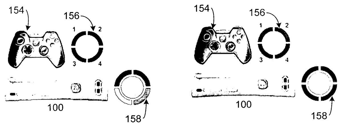
Referring toFIG. 2, there is illustrated an exemplary wireless controller154having a four quadrant LED indicator156(and enlarged view) and console100having a four quadrant indicator158. The controller154also includes vibration feedback, mini-joysticks, pressure-sensitive buttons, etc. A game is shown on the screen160. The console indicator158is shown surrounding a power button, however, other configurations may be implemented. Each quadrant of the ring may be illuminated by an LED, which may be either a single color or bi-colored to illuminate in plural colors. As will be described below, the quadrants may be illuminated in patterns indicating the notifications, system status, binding and discovery.
To support an environment where multiple consoles100and wireless controllers154may coexist, each controller is logically “bound” to a single console100so that a link is established with only that console100. A controller154can not be bound to more than one console100at a time. Binding is the process by which a console100transmits information to a controller154that will enable that controller to establish a link with the console100. Once “bound” to a console100, the controller154attempts to establish a link with the console100to which it is bound whenever the controller154is turned on.
It is preferable that binding information is retained only in the controller. Binding is one to one with respect to the controller154, but it is one to many with respect to the console100. Binding, thus, persists on the controller154across battery discharge/charge cycles, until a new binding relationship is established. Establishing a binding relationship is attempted when a BIND button on the console and a BIND button on a wireless controller154are pressed within a predetermined period of time of each other. Successfully establishing a binding relationship is dependent on successfully establishing a radio communication link and executing a mutual verification algorithm.
The console is preferably powered up before pressing its BIND button. If a user initiates binding on a controller154that is currently connected to a console100, the controller154drops the connection to the console100prior to attempting the binding process. As the binding process operates, a status notification screen may display binding and discovery process (e.g., binding . . . bound . . . discovered). Binding is a one to one event. In other words, pressing the binding button on the console100will bind one controller154at a time. To bind a second controller154, the BIND button on the console100is pressed a second time. If binding is not successful within a predetermined time, the console100or controller154will automatically time out and return to a previous state such that the previous binding relationship is not lost.
There are four virtual controller ports on the console100, referred to herein as “Vports.” The Vports represent the active game controllers connected to the console100, either wired or wirelessly. The numbered Vports are automatically assigned to controllers in the order they are connected to the console100. Each Vport is represented by a quadrant of the LED indicator156and the console indicator158. “Discovery” is the process during which a wired or wireless game device is recognized by the console100, assigned a Vport, and made available for game play.
Thus, the acts of “binding” and “discovery” are preferably two different acts. The act of binding is initiated by pressing the BIND buttons on the controller and console. Once bound, the controller will begin the discovery process, and if successful, will be assigned the first available Vport, which in this case is Vport1as described. If one to three controllers had previously been bound and discovered, then the next controller discovered would be assigned Vport2,3, or4respectively. If, four controllers were already discovered, then the binding process could still be performed, however no Vport would be available to assign, so the controller would not be assigned a Vport, however it would still be bound to the console and available to be discovered if one of the other four controllers were either turned off or bound to a new console.
Referring toFIGS. 3 and 4, there is a visualization of the binding and discovery processes and how the LED indicator156and the console indicator158visually convey the processes to players. As shown inFIG. 3, the controller has been powered on and the BIND button on the console100and the controller have been pressed. After the binding process has completed, the discovery process takes place. Because this is the first controller to be discovered by the console100, it is associated with Vport1and the top left quadrant of the indicators156and158will illuminate to signal the connection. As shown inFIG. 4, if more than one controller is discovered by the console100, the other quadrants of indicator158are illuminated in succession. Thus, if two controllers are connected, two quadrants of the indicator158will illuminate, and so on up to four controllers and four quadrants. It is noted that while additional quadrants are successively illuminated on the console, only a single quadrant is illuminated on any single controller at a time.
The position of the quadrant preferably corresponds to the Vport as follows:
1, top left quadrant
2, top right quadrant
3, lower left quadrant
4, lower right quadrant
In addition, as shown inFIG. 4, where multiple players are playing, the position of the players on the screen correspond to the quadrant assigned to their particular controller.
Vports are preferably assigned in ascending order (1 through 4), according to the following rules:
If the system is powered up by a controller, that controller (wired or wireless) is assigned Vport1.
Wired controllers plugged into the console are automatically assigned the next available Vport According to the following order:Controllers connected via hub to USB Port A.Controller directly plugged into USB Port A (e.g., controller142(1)).Controllers connected via hub to USB Port B.Controller directly plugged into USB Port B (e.g., controller142(2)).Controllers connected via hub to USB Port CController directly plugged into USB Port C
Vports are vacated as controllers are unplugged or powered off. Logically, a wireless controller that is powered off is treated the same as a wired controller that is unplugged from the console100. Once powered-up, the console100will assign additional wired and wireless controllers to available Vports in the order in which they are connected or powered up. During game play, the game will be notified when a controller is unplugged. In the event that the controller that is unplugged is currently being used in the game, the game will pause and display a disconnect message (see,FIG. 8). The game also notifies the console100that the vacated Vport is the next to be repopulated should a controller be reconnected. Should subsequent disconnects occur, the console notifies the game and the game reports back with the next Vport to populate. The console maintains in a Last-In-First-Out stack for the next Vport assignment requested by the game.
Thus, as controllers are reconnected, they are assigned to Vports according to the following rules:
If a Next Vport stack has a value in it, the controller is assigned to the specified Vport and the Vport is popped off the stack.
If the Next Vport stack is empty, the controller is assigned to the lowest numbered vacant Vport.
If no there are no vacant Vports, then the controller is not assigned a Vport. If the controller is wireless, it displays the failure to connect display and is powered down. If the controller is wired, no quadrant is illuminated on the controller.
A battery charging cable may be used to attach a wireless controller154to a console100in the event that a wireless connection is not possible or when battery power in not available. In this condition, the wireless controller154operates like a wired controller and the console100provides the power to operate the controller154. However, if the controller154is plugged into a battery charger, not the console100, it will continue to operate as a wireless controller154. If the controller154is powered off while charging, the controller154will release its Vport.
The wireless controller may attempt to maximize battery life through power management. In a low power state, the controller154decreases its communication rate with the console154. The assigned Vport assignment is maintained in this state. However, if the controller154is not used for a predetermined period of time after entering the low power state, it releases the Vport and powers off.
The controller154may also provide notifications to a player via the LED indicator156and LEDs, which can illuminate in a selected color (e.g., green, red and orange). The quadrants can be illuminated in patterns indicating notifications, system status, binding, discovery, and system errors. For example, the LED may indicate that the controller is connected to a console, an alert state, and messages. Further, onscreen notifications may be presented in conjunction with the LED signals. Exemplary onscreen notifications may include game invitations, low battery warnings, system errors, etc.
An exemplary set of notifications and warnings are shown inFIG. 2. To convey the notifications and warnings, the LEDs preferably operate in three basic patterns: cycle, flash and on. For example, inFIG. 5, the indicator158may illuminate the LEDs such that they cycle to indicate that the BIND button on the console100has been pressed. Similarly, inFIG. 6, the indicator156may illuminate the LEDs such that they cycle to indicate that the BIND button on the controller154has been pressed.FIG. 7shows that all LEDs may be flashed on both the indicators156and158to show discovery of the controller154.
As noted above, messages and warnings may be presented in a UI.FIG. 8shows a warning that a controller has been disconnected from the console100and it should be reconnected. A basic controller status screen may also be presented the displays the signal strength and percentage of battery power of a wireless controller and also provides access to a manual Sleep button.
Referring toFIGS. 9-10, a notification may be provided via a small onscreen panel162which notifies the player that they have a message, system message or system problem (e.g., low battery, wireless signal loss). The condition may be indicated on the indicators156and158by illuminating the quadrant to which the controller154is bound and to which the message is intended.FIG. 11illustrates a message in the panel162conveying that another player would like to chat.FIG. 12illustrates onscreen messaging when multiple players and playing with controllers bound to the console.
Those of ordinary skill in the art will now understand that any message or notification may be conveyed to the user via the LED indicators and onscreen notifications. The messages or notifications may be presented via numerous combinations of colors, lighting patterns and UI messages and the examples provided herein are neither exhaustive nor limiting of the present invention. In addition, notifications could also be indicated using an audible sound or vibration in the controller.
In accordance with a feature of the invention, the console100may be operated either in a horizontal or vertical orientation. A gravity-sensing switch is used in the console100to detect the orientation and adjusts the display presentation such that the spatial relationship between Vport number and the display are maintained as indicated above.
The LED notification system of the present invention is designed to provide users with a simple, consistent way in which to add and remove controllers from the console, while conveying port assignments, messages, notifications and system errors. While the present invention has been described in connection with the preferred embodiments of the various Figs., it is to be understood that other similar embodiments may be used or modifications and additions may be made to the described embodiment for performing the same function of the present invention without deviating therefrom.
Claims
- A gaming controller, comprising: a plurality of buttons;and a plurality of visual indicators, each of which corresponds to a different one of a plurality of ports of an associated gaming console;wherein one of the plurality of visual indicators is illuminated to notify a user which one of the corresponding plurality of ports of the associated gaming console has been assigned to the gaming controller.
- The gaming controller of claim 1 , wherein each of said visual indicators has a corresponding indicator on said associated gaming console.
- The gaming controller of claim 2 , further comprising a bind button, wherein when said bind button is pressed, said gaming controller will bind with said associated gaming console, and wherein said visual indicator is illuminated to indicate that said gaming controller is bound to said associated gaming console.
- The gaming controller of claim 3 , wherein said visual indicators are arranged as quadrants, and one of said quadrants is associated with said gaming controller so long as said gaming controller is bound to said associated gaming console via a discovery process.
- The gaming controller of claim 1 , further comprising at least one of an audible component and a vibration controller, wherein messages are conveyed by said at least one of said audible component and said vibration controller.
- The gaming controller of claim 1 , wherein a predetermined sequence of illuminating said LED is utilized to convey messages to the user.
- A method of associating a gaming controller to a gaming console, comprising at the gaming controller: establishing a connection with said gaming console, wherein the gaming controller is assigned to one of a plurality of ports of the gaming console;illuminating one of a plurality of visual indicators on the gaming controller, each visual indicator corresponding to a respective one of a plurality of different ports on the gaming console, the illuminated visual indicator indicating on the gaming controller which port of the plurality of ports of the gaming console has been assigned to the gaming controller;and making said gaming controller available for game play.
- The method of claim 7 , wherein said establishing a connection comprises a bind sequence comprising: initiating said bind sequence via a first action at said gaming controller;initiating a second action at said gaming console within a predetermined period of time of said first action, whereby said gaming controller is recognized by said gaming console;and storing, in said gaming controller, binding information.
- The method of claim 7 , further comprising: requesting a port assignment from said gaming controller.
- The method of claim 9 , further comprising at the gaming console: determining a number of assigned ports;and assigning a next available port to said gaming controller.
- The method of claim 10 , further comprising at the gaming console: determining if a last available port has already been assigned;and if so, maintaining said binding information in said gaming controller and assigning a previously used port as said next available port to said gaming controller when said previously used port is released by a second gaming controller.
- The method of claim 9 , further comprising providing an indication that said controller has been discovered by said gaming console.
- The method of claim 12 , wherein said indication is provided by a plurality of LEDs on said gaming controller.
- The method of claim 13 , wherein said plurality of LEDs comprises four quadrants, each of said quadrants representing a different one of said plurality of ports to which the gaming controller may be assigned, said method further comprising illuminating one of said quadrants to indicate which of said plurality of ports has been assigned to the gaming controller.
- The method of claim 14 , further comprising providing notifications via said one of said quadrants to a player using said gaming controller.
- The method of claim 9 , wherein said controller is either a wired controller or a wireless controller.
- The method of claim 7 , wherein each of said plurality of ports is a virtual port.
Disclaimer: Data collected from the USPTO and may be malformed, incomplete, and/or otherwise inaccurate.