Illustrative Figure
Abstract
A game controller includes a casing, a control circuit module received in the casing, a plurality of controlling units embodying as a left control stick, a direction key, a function key, and a right control stick respectively, wherein at least two of the controlling units form as two interchangeable controlling units respectively which are detachable from the casing. A plurality of terminal seats are spacedly provided on the casing for detachably retaining the interchangeable controlling units in position, wherein the number of the terminal seats are corresponding to the number of the interchangeable controlling units to be interchangeably mounted at the casing. The interchangeable controlling units are detachably coupled at the terminal seats to electrically connect to the control circuit module. The positions of the interchangeable controlling units are interchanged according to the game setting and players' habits.
Description
DETAILED DESCRIPTION OF THE PREFERRED EMBODIMENT Referring toFIGS. 1 to 4dof the drawings, a game controller according to a first embodiment of the present invention is illustrated, wherein the game controller comprises a casing10, such as a hand-held casing, which comprises a main body100, and two spaced apart handle bodies101extending downwardly from the two sides of the main body100. The game controller further comprises a control circuit module18supported within the casing10, wherein the control circuit module18is adapted to communicatively connect to a game console via a wireless communication, such as “Bluetooth”, or a wired communication such as USB to send the control signal from the game controller to the game console for playing the electronic game. The game controller further comprises a plurality of controlling units provided at the casing10to electrically connect to the control circuit module18, wherein the controlling units are preferably embodied as a left control stick11, a direction key12, a function key13, and a right control stick14, a START key15, a SELECT key16, and a plurality of firing keys17respectively. Accordingly, at least two of the controlling units are embodied as the interchangeable controlling units. The game controller further comprises a controller interchanging arrangement for detachably retaining the interchangeable controlling units at the casing10. Accordingly, at least the left control stick11, the direction key12, the function key13, and the right control stick14can be set as four interchangeable controlling units which are detachable from the casing10. The controller interchanging arrangement comprises a plurality of terminal seats102spacedly provided at the main body100of the casing. Accordingly, there are four terminal seats102spacedly formed at the main body100, wherein each of the terminal seats102has a cylindrical shape indented on the main body100to form a cavity thereat for receiving the interchangeable controlling unit. Each of the terminal seats102further comprises a plurality of first connectors103, ...
DETAILED DESCRIPTION OF THE PREFERRED EMBODIMENT
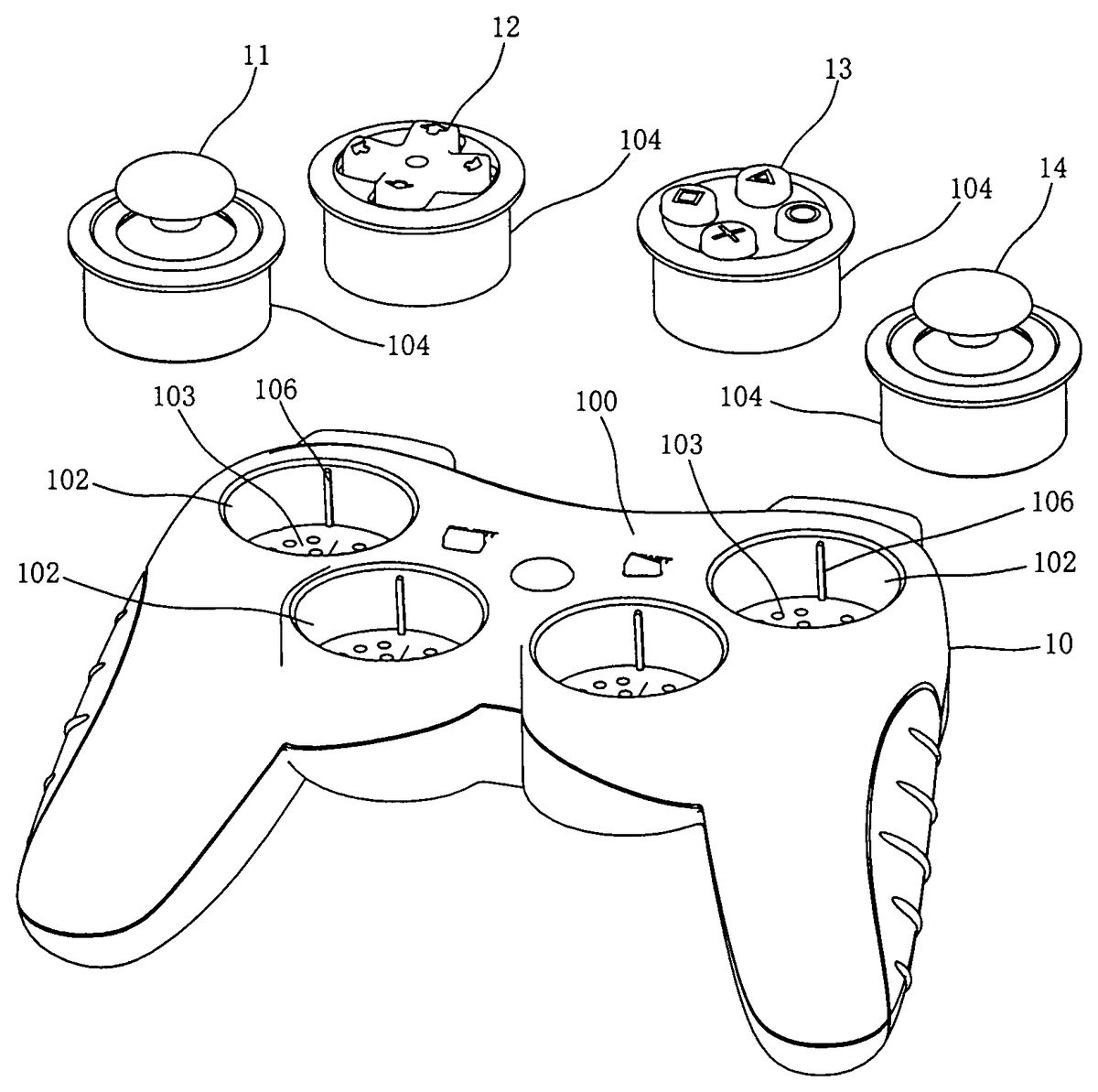
Referring toFIGS. 1 to 4dof the drawings, a game controller according to a first embodiment of the present invention is illustrated, wherein the game controller comprises a casing10, such as a hand-held casing, which comprises a main body100, and two spaced apart handle bodies101extending downwardly from the two sides of the main body100. The game controller further comprises a control circuit module18supported within the casing10, wherein the control circuit module18is adapted to communicatively connect to a game console via a wireless communication, such as “Bluetooth”, or a wired communication such as USB to send the control signal from the game controller to the game console for playing the electronic game.
The game controller further comprises a plurality of controlling units provided at the casing10to electrically connect to the control circuit module18, wherein the controlling units are preferably embodied as a left control stick11, a direction key12, a function key13, and a right control stick14, a START key15, a SELECT key16, and a plurality of firing keys17respectively. Accordingly, at least two of the controlling units are embodied as the interchangeable controlling units. The game controller further comprises a controller interchanging arrangement for detachably retaining the interchangeable controlling units at the casing10. Accordingly, at least the left control stick11, the direction key12, the function key13, and the right control stick14can be set as four interchangeable controlling units which are detachable from the casing10. The controller interchanging arrangement comprises a plurality of terminal seats102spacedly provided at the main body100of the casing. Accordingly, there are four terminal seats102spacedly formed at the main body100, wherein each of the terminal seats102has a cylindrical shape indented on the main body100to form a cavity thereat for receiving the interchangeable controlling unit. Each of the terminal seats102further comprises a plurality of first connectors103, preferably four sets of connectors, provided at the bottom wall of the terminal seat102, wherein the first connectors103are electrically extended from the control circuit module18. Accordingly, the four sets of first connectors103are arranged to electrically couple with the four interchangeable controlling units, i.e. the left control stick11, the direction key12, the function key13, and the right control stick14, respectively. In other words, each set of the first connectors103is correspondingly aligned to couple with the respective interchangeable controlling unit, wherein each set contains at least one of the first connectors103. Therefore, the number of set of the first connectors103is corresponding to the number of the interchangeable controlling units. Each of the interchangeable controlling units further comprises a cylindrical plugging body104detachably sliding into the terminal seat102, and at least a second connector105provided at a bottom side of the plugging body104such that when the plugging body104is detachably engaged with the respective terminal seat102, the second connector105is electrically engaged with one of the first connectors103of the respective terminal seat102. Therefore, when the four plugging bodies104of the interchangeable controlling units are selectively and detachably engaged with the four terminal seats102, the four second connectors105of the interchangeable controlling units are correspondingly engaged with four different first connectors103respectively. Consequently, the interchangeable controlling units are electrically connected with the control circuit module18to form a complete functional game controller.
Accordingly, the four terminal seats102have the same quadrant arrangement of the first connectors103to be distributed. For example, the four sets of first connectors103are arranged in four different quadrants. In other words, the number of quadrants at each of the terminal seats102is corresponding to the number of the interchangeable controlling units. The first quadrant of the terminal seat102is assigned to the first connector103for connecting the left control stick11. The second quadrant of the terminal seat102is assigned to the first connector103for connecting the direction key12. The third quadrant of the terminal seat102is assigned to the first connector103for connecting the function key13. The forth quadrant of the terminal seat102is assigned to the first connector103for connecting the right control stick14. Correspondingly, the left control stick11has its corresponding second connector105located on the first quadrant of the bottom of the plugging body104thereof corresponding to the first connector103on the first quadrant of the bottom of the terminal seat102. The function key13has its corresponding second connector105located on the second quadrant of the bottom of the plugging body104thereof corresponding to the first connector103on the second quadrant of the bottom of the terminal seat102. The direction key12has its corresponding second connector105located on the third quadrant of the bottom of the plugging body104thereof corresponding to the first connector103on the third quadrant of the bottom of the terminal seat102. The right control stick14has its corresponding second connector105located on the forth quadrant of the bottom of the plugging body104thereof corresponding to the first connector103on the forth quadrant of the bottom of the terminal seat102.
Preferably, the first connectors103at the bottom of the terminal seats102and the second connectors105at the bottom of the plugging bodies104are contact terminals such that the first connector103is electrically contacted with the second connector105for electrical connection. Alternatively, other types of connectors are also available.
In the preferred embodiment, the first connectors103are located on the bottom of the terminal seats102, and the second connectors105are located on the bottom of the plugging bodies104. Obviously, the locations of the first and second connectors103,105are not limited to these locations. For example, the first connectors103can be placed at the side wall of the terminal seats102, and the second connector105can be placed at the side wall of the plugging body104of the interchangeable controlling units correspondingly.
The terminal seat102further comprises a positioning ridge106protruding vertically from the side wall thereof. The plugging body104of the interchangeable controlling units further comprises a positioning slot107indently formed on the side wall thereof corresponding to the positioning ridge106of the terminal seat102. When the interchangeable controlling unit is installed into the terminal seat102, the positioning ridge106is slidably coupled with the positioning slot107to guide the installation of the interchangeable controlling unit relating to the terminal seat102. By the coupling of the positioning ridge106and the positioning slot107, the relative position of the plugging body104and the terminal seat102are guaranteed to ensure the electrical connection between the first and second connectors103,105. Obviously, other methods of positioning can also be used. For example, forming positioning holes on the bottom of the terminal seat102, and forming positioning poles on the bottom of the plugging body104correspondingly. In other words, the positioning hole and pole configuration can be used for positioning and aligning the connection between the first and second connectors103,105.
Preferably, the handle bodies101of the casing10comprise an anti-slipping layer108made of soft rubber material on the outer sides thereof, wherein the anti-slipping layer108has protruding patterns109. The anti-slipping layer108helps the player to hold the handle bodies101, and to improve the hand feeling for holding.
As shown inFIG. 5, a second embodiment of the game controller illustrates an alternative embodiment of the first embodiment. Accordingly, the left control stick11, direction key12, and right stick14are interchangeable controlling units respectively, while the function key13is stationary provided on the casing10such that the function key13cannot be detached therefrom. Relatively, the main body100of the casing10comprises three terminal seats102for receiving the three interchangeable controlling units mentioned above. The structure of the interchangeable controlling units and the terminal seats102are the same as the first embodiment.
As shown inFIG. 6, a third embodiment of the game controller illustrates another alternative embodiment of the first embodiment.
Accordingly, the left control stick11and direction key12are embodied as two interchangeable controlling units, while the function key13and the right control stick14are stationary provided on the casing10, such that the function key13and the right control stick14cannot be detached from the casing10. According to the preferred embodiment, the left control stick11and direction key12are integrally formed in one piece control member with an elongated structure. The main body100of the casing10comprises two terminal seats102for receiving the two the function key13and the right control stick14mentioned above. In particularly, the two terminal seats102are integrated to form an elongated cavity for the control member detachably coupling thereat. In other words, the positions of the left control stick11and direction key12can be interchangeably switched by turning the control member.
In conclusion, in the gamepad of the present invention, all or at least two of the left control stick11, the direction key12, the function key13, and the right stick14can be formed as the interchangeable controlling units which are detachable from the casing10. Therefore the positions of these controlling units can be interchanged according to the control configurations of the electronic game and the player's habit to satisfy different requirements of different electronic games and different players.
One skilled in the art will understand that the embodiment of the present invention as shown in the drawings and described above is exemplary only and not intended to be limiting.
It will thus be seen that the objects of the present invention have been fully and effectively accomplished. It embodiments have been shown and described for the purposes of illustrating the functional and structural principles of the present invention and is subject to change without departure from such principles. Therefore, this invention includes all modifications encompassed within the spirit and scope of the following claims.
Claims
- A game controller, comprising: a casing;a control circuit module received in said casing for operatively linking to a game console;a plurality of controlling units, wherein at least two of said controlling units form as two interchangeable controlling units respectively which are detachable from said casing;and a controller interchanging arrangement, which comprises: a plurality of terminal seats spacedly provided on said casing, wherein each of said interchangeable controlling units is selectively and detachably mounted at said casing at one of said terminal seats to electrically couple with said control circuit module so as to selectively relocate said interchangeable controlling units at said casing, wherein the number of said terminal seats are corresponding to the number of said interchangeable controlling units to be interchangeably mounted at said casing;a plurality set of first connectors provided at each of said terminal seats to electrically extend from said control circuit module, wherein the number of each set of said first connectors at each of said terminal seats are corresponding to the number of said interchangeable controlling units;and a plurality of second connectors provided at said interchangeable controlling units and electrically engaged with one set of said first connectors when said interchangeable controlling unit is detachably mounted at said respective terminal seat;wherein each of said terminal seats has a plurality of quadrants, wherein the number of said quadrants is corresponding to the number of said interchangeable controlling units, wherein each set of said first connectors is provided at each of said quadrants of said terminal seat, such that two or more sets of said first connectors are provided at each of said terminal seats.
- The game controller, as recited in claim 1 , wherein said first and second connectors are contact terminals such that when said interchangeable controlling unit is detachably mounted at said respective terminal seat, said first and second connectors are electrically contacted with each other to electrically connect said interchangeable controlling unit with said control circuit module.
- The game controller, as recited in claim 2 , wherein all of said terminal seats have the same quadrant arrangement of said first connectors to be distributed.
- The game controller, as recited in claim 3 , wherein said first connectors are provided at a bottom wall of each of said terminal seats while said second connector is provided at a bottom side of said interchangeable controlling unit to align with said first connector when said interchangeable controlling unit is detachably mounted at said terminal seat.
- The game controller, as recited in claim 4 , wherein each of said terminal seats is indentedly formed on said casing to form a cavity thereat, wherein each of said interchangeable controlling units comprises a plugging body extended downwardly to slidably and detachably engaged with said cavity of said terminal seat.
- The game controller, as recited in claim 5 , wherein each of said plugging bodies has a cylindrical shape and each of said terminal seats has a corresponding cylindrical shape to receive said plugging body thereat.
- The game controller, as recited in claim 6 , wherein said interchangeable controlling units are selected from the group consisting of a left control stick, a direction key, a function key, and a right control stick, a START key, a SELECT key, and a plurality of firing keys.
- The game controller, as recited in claim 7 , wherein said controller interchanging arrangement further comprises a positioning ridge vertically protruding from a side wall of each of said terminal seats and a positioning slot vertically formed on an outer wall of said each of said interchangeable controlling units for said positioning ridge slidably engaging with said positioning slot so as to ensure a correct alignment said second connectors and said corresponding set of said first connectors.
- The game controller, as recited in claim 1 , wherein all of said terminal seats have the same quadrant arrangement of said first connectors to be distributed.
- The game controller, as recited in claim 1 , wherein said first connectors are provided at a bottom wall of each of said terminal seats while said second connector is provided at a bottom side of said interchangeable controlling unit to align with said first connector when said interchangeable controlling unit is detachably mounted at said terminal seat.
- The game controller, as recited in claim 1 , wherein each of said terminal seats is indentedly formed on said casing to form a cavity thereat, wherein each of said interchangeable controlling units comprises a plugging body extended downwardly to slidably and detachably engaged with said cavity of said terminal seat.
- The game controller, as recited in claim 1 , wherein said interchangeable controlling units are selected from the group consisting of a left control stick, a direction key, a function key, and a right control stick, a START key, a SELECT key, and a plurality of firing keys.
- The game controller, as recited in claim 1 , wherein said controller interchanging arrangement further comprises a positioning ridge vertically protruding from a side wall of each of said terminal seats and a positioning slot vertically formed on an outer wall of said each of said interchangeable controlling units for said positioning ridge slidably engaging with said positioning slot so as to ensure a correct alignment between said second connectors and said corresponding set of said first connectors.
Disclaimer: Data collected from the USPTO and may be malformed, incomplete, and/or otherwise inaccurate.