U.S. Pat. No. 8,337,313
COMPUTER-READABLE STORAGE MEDIUM HAVING GAME PROGRAM STORED THEREIN, GAME APPARATUS, GAME SYSTEM, AND GAME PROCESSING METHOD
AssigneeNintendo Co., Ltd.
Issue DateNovember 23, 2010
Illustrative Figure
Abstract
Angular velocity data for specifying the position and the orientation of the first controller is inputted to a game apparatus. Based on the angular velocity data, the swing direction of the first controller is determined, and whether or not a sword object that acts in a virtual game space will collide with an enemy object is determined. If it has been determined that the sword object will collide with the enemy object, whether or not to perform hitting processing for the enemy object is determined based on the swing direction of the first controller.
Description
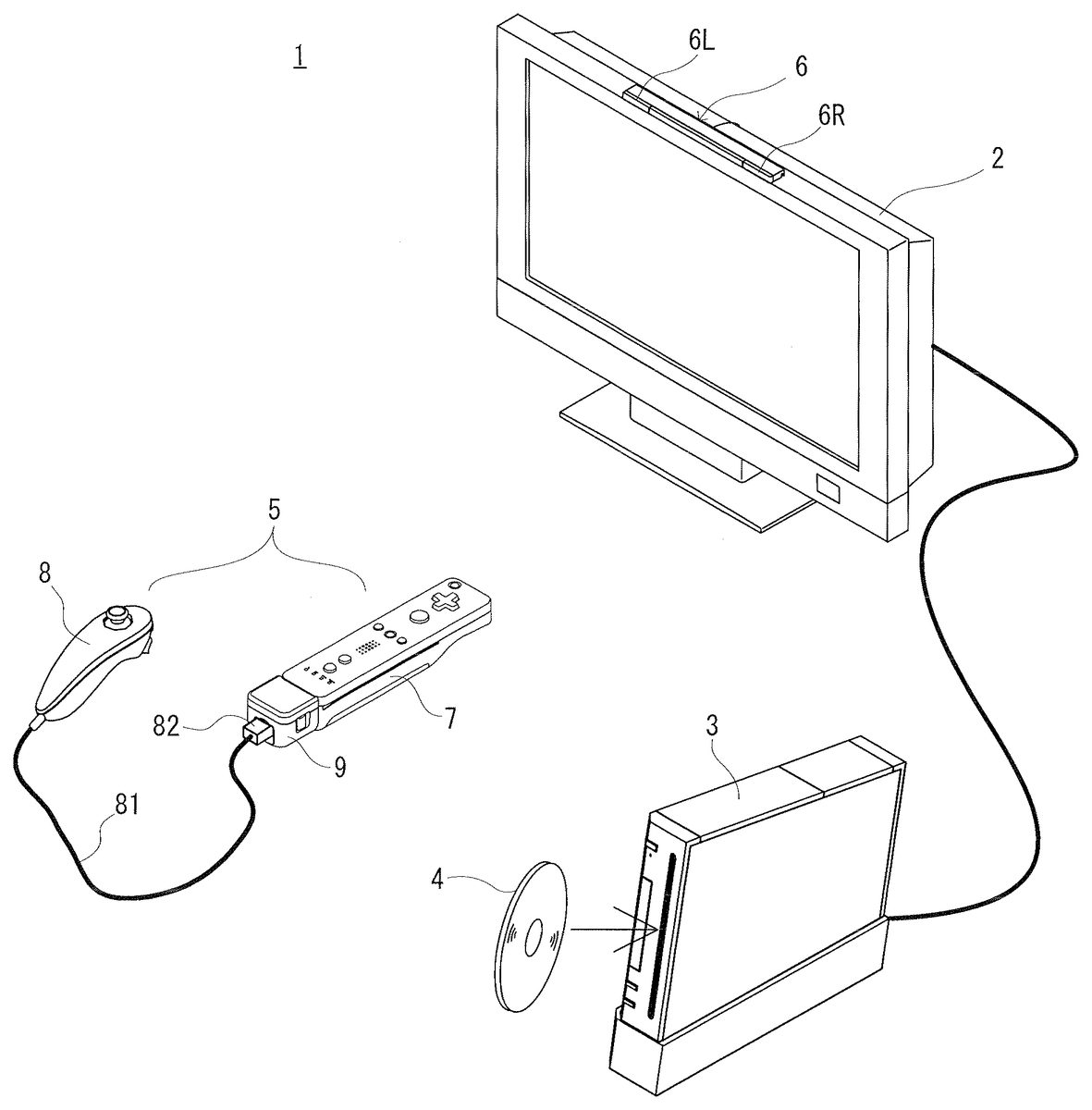
DESCRIPTION OF THE EXAMPLE EMBODIMENTS In the following, an embodiment of the present invention will be described with reference to the drawings as appropriate.FIG. 1is an external perspective view of a game system1which includes a game apparatus3according to an embodiment of the present invention. In the present embodiment, the present invention will be described taking as an example a case where a game apparatus is the game apparatus3of stationary type. However, the game apparatus may be, for example, a portable type game apparatus in which a game apparatus and a display device are integrally formed. [Whole Configuration of Game System1] Firstly, an overview of components of the game system1will be described. InFIG. 1, the game system1includes a liquid crystal television2, the game apparatus3, an optical disc4, a marker unit6, and a controller5. In the game system1, the game apparatus3executes a game process based on a game operation performed by a player using the controller5. The optical disc4, which is an exemplary information storage medium changeable with respect to the game apparatus3, is detachably loaded into the game apparatus3. A game program that is executed in the game apparatus3is stored on the optical disc4. On a front surface of the game apparatus3, a slot through which the optical disc4is inserted is provided. The game apparatus3executes a game process by reading and executing the game program stored on the optical disc4which has been inserted through the slot. The liquid crystal television2is connected via a connection cord to the game apparatus3. As will be described later, the game apparatus3generates an image (hereinafter, referred to as a game image) of a virtual game space including an object seen from a viewpoint of a virtual camera placed in the virtual game space, and outputs the image to the liquid crystal television2. This series of processes ...
DESCRIPTION OF THE EXAMPLE EMBODIMENTS
In the following, an embodiment of the present invention will be described with reference to the drawings as appropriate.FIG. 1is an external perspective view of a game system1which includes a game apparatus3according to an embodiment of the present invention. In the present embodiment, the present invention will be described taking as an example a case where a game apparatus is the game apparatus3of stationary type. However, the game apparatus may be, for example, a portable type game apparatus in which a game apparatus and a display device are integrally formed.
[Whole Configuration of Game System1]
Firstly, an overview of components of the game system1will be described. InFIG. 1, the game system1includes a liquid crystal television2, the game apparatus3, an optical disc4, a marker unit6, and a controller5. In the game system1, the game apparatus3executes a game process based on a game operation performed by a player using the controller5.
The optical disc4, which is an exemplary information storage medium changeable with respect to the game apparatus3, is detachably loaded into the game apparatus3. A game program that is executed in the game apparatus3is stored on the optical disc4. On a front surface of the game apparatus3, a slot through which the optical disc4is inserted is provided. The game apparatus3executes a game process by reading and executing the game program stored on the optical disc4which has been inserted through the slot.
The liquid crystal television2is connected via a connection cord to the game apparatus3. As will be described later, the game apparatus3generates an image (hereinafter, referred to as a game image) of a virtual game space including an object seen from a viewpoint of a virtual camera placed in the virtual game space, and outputs the image to the liquid crystal television2. This series of processes are performed in units of a frame (e.g., at intervals of 1/60 sec) in this embodiment. The liquid crystal television2receives a game image outputted from the game apparatus3in this manner, and displays the game image on a screen.
The marker unit6is provided in the vicinity of the screen of the liquid crystal television2(on an upper side of the screen inFIG. 1). The marker unit6comprises two markers6R and6L at both ends thereof. Specifically, the marker6R includes one or more infrared LEDs that output infrared light toward the front of the liquid crystal television2(the same is true of the marker6L). The marker unit6is connected to the game apparatus3, so that the game apparatus3can control ON/OFF of each infrared LED included in the marker unit6. The marker unit6is also provided with a microphone (not shown). Audio information inputted through the microphone is inputted to the game apparatus3.
The controller5is input means that is operated by the player. In the present embodiment, the controller5includes a first controller7and a second controller8each of which can be held by the player with one hand of the player, and a gyro sensor unit9that is attached, in a detachable manner, to the first controller7. The first controller7is an input apparatus that is operated by the player. The first controller7generates operation data indicating a content of an operation performed with respect to the first controller7. The gyro sensor unit9functions as state detection means that detects the position and the orientation of the first controller7, with the gyro sensor unit9being attached to the first controller7. The gyro sensor unit9detects the angular velocity of the first controller7, and outputs angular velocity data indicating the detected angular velocity, to the first controller7. Here, the angular velocity data is a state signal for specifying the position and the orientation of the first controller7, which indicates the state of the first controller7. The second controller8generates operation data indicating an operation performed with respect to itself. The operation data is outputted to the first controller7via the gyro sensor unit9. The first controller7transmits, to the game apparatus3, controller data including the operation data of the first controller7, the operation data of second controller8, the angular velocity data of the gyro sensor unit9, and the like.
The first controller7and the game apparatus3are connected via wireless communication, for transmission of the controller data. In this embodiment, for example, the Bluetooth (registered trademark) technology is used for wireless communication between the first controller7and the game apparatus3. Note that, in another embodiment, the first controller7and the game apparatus3may be connected via wired communication.
[External Configuration of First Controller7]
FIG. 2is a perspective view of the first controller7and the gyro sensor unit9as seen from a top rear side thereof.FIG. 3is a perspective view of the first controller7as seen from a bottom front side thereof.
As shown inFIG. 2andFIG. 3, the first controller7includes a housing71which is formed by, for example, plastic molding. The housing71has a generally parallelepiped shape extending in a longitudinal direction (Z-axis direction inFIG. 2andFIG. 3) from front to rear. The overall size of the housing71is small enough to be held by one hand of an adult or even a child. An operation section72is placed on the housing71.
An operation section72provided on the upper surface of the housing71includes a cross key72a, operation buttons72bto72g, and an operation button72h.
The cross key72ais a cross-shaped four-direction push switch. The cross key72aincludes operation portions corresponding to four directions (front, rear, right and left), which are respectively located on cross-shaped projecting portions so as to be arranged at intervals of 90 degrees. A player selects one of the front, rear, right and left directions by pressing one of the operation portions of the cross key72a. Through an operation of the cross key72a, the player can, for example, select an option from a plurality of options.
Each of the operation buttons72bto72goutputs a corresponding operation signal when the player presses a head the operation button. For example, functions as a number one button, a number two button and an A button are assigned to the operation buttons72bto72d, respectively. Also, functions as a minus button, a home button and a plus button are assigned to the operation buttons72eto72g, respectively. Operation functions are assigned to the operation buttons72bto72gin accordance with the game program executed by the game apparatus3. It is noted that the operation button72fhas a top surface thereof buried in the top surface of the housing71, so as not to be inadvertently pressed by the player.
The operation button72his a power switch for turning on and off the power to the game apparatus3by remote control. The operation button72hhas a top surface thereof buried in the top surface of the housing71, and is an operation button of the same type as the operation button72f.
Besides the operation section72, a plurality of LEDs702are provided on the upper surface of the housing71. Here, controller types (numbers) are assigned to the first controllers7such that the first controllers7are distinguishable from each other. The LEDs702are used for, for example, informing the player of the controller type which is currently set for the first controller7. More specifically, when the first controller7transmits controller data to the wireless controller module19(seeFIG. 5), one of the plurality of LEDs702which corresponds to the controller type of the first controller7is lit up.
On the top surface of the housing71, a plurality of holes711are provided between the operation button72band the operation buttons72eto72gfor emitting sound from a speaker706included in the housing71(seeFIG. 6).
As shown inFIG. 3, a recessed portion is formed on a bottom surface of the housing71. The recessed portion is formed in a position in which an index finger or middle finger of the player is located when the player holds the first controller7such that the front surface thereof faces the makers6L and6R. On the rear side of a slope surface of the recessed portion, an operation button72iis provided. The operation button72ioutputs an operation signal assigned to the operation button72iby the player pressing the head of the operation button72i, and functions as, for example, a B button.
On a front surface of the housing71, an imaging device743(seeFIG. 6) constituting a part of an imaging information calculation section74(seeFIG. 3) is provided. The imaging information calculation section74is a system for analyzing image data of an image taken by the first controller7, thereby identifying an area having a high brightness in the image and detecting a position of a center of gravity, a size and the like of the area. The imaging information calculation section74has, for example, a maximum sampling period of about 200 frames/sec, and therefore can trace and analyze even a relatively fast motion of the first controller7. A configuration of the imaging information calculation section74will be described later in detail. On a rear surface of the housing71, a connector73(seeFIG. 2) is provided. The connector73is, for example, an edge connector.
[External Configuration of Gyro Sensor Unit9]
Though not shown inFIG. 2, a connector91(seeFIG. 6) that can be connected to the connector73of the first controller7is provided to the front surface of the gyro sensor unit9. When the connector91is connected to the connector73, the gyro sensor unit9is physically and electrically connected to the first controller7. The gyro sensor unit9detects angle velocities around three axes (X-axis, Y-axis, and Z-axis) of the first controller7while the gyro sensor unit9and the first controller7being unified. After the angular velocities of the first controller7have been detected, angular velocity data indicating the detection result is outputted from the gyro sensor unit9to the first controller7.
A connector92(seeFIG. 6) that can be connected to the connector82(seeFIG. 1) of the second controller8is provided to the rear surface of the gyro sensor unit9. When the connector82is connected to the connector92, the second controller8is connected to the first controller7via the gyro sensor unit9. It is noted thatFIG. 2shows a state where a connector cover93is attached to the connector92, and therefore, the connector92is not shown.
Release buttons94are provided at the side surfaces of the gyro sensor unit9. The gyro sensor unit9includes hooks projecting from the front surface of the gyro sensor unit9, which are not shown. When the gyro sensor unit9is to be attached to the first controller7, the hooks are inserted into the housing71via holes76(seeFIG. 2) formed on the rear surface of the housing71, and then the hooks are engaged with the inner wall of the housing71. Thus, the gyro sensor unit9is fixed to the first controller7. The release buttons94are interlinked with the hooks. The player can detach the gyro sensor unit9from the first controller7by pulling out the hooks from the housing71while pressing the release button94.
[External configuration of Second Controller8]
The connector82(seeFIG. 1) of the second controller8can be connected to the connector73(seeFIG. 2andFIG. 6) of the first controller7, or the connector92(seeFIG. 6) of the gyro sensor unit9. When the connector82is connected to the connector73, operation data from the second controller8is directly inputted to the first controller7via a cable81and the connector82. On the other hand, when the connector91is connected to the connector73, and the connector82is connected to the connector92, operation data from the second controller8is inputted to the first controller7via the cable81, the connector82, and the gyro sensor unit9.
FIG. 4is a perspective view of the second controller8.FIG. 4(A)is a perspective view of the second controller8as seen from a top rear side thereof, andFIG. 4(B)is a perspective view of the second controller8as seen from a bottom front side thereof. It is noted that inFIG. 4, the cable81and the connector82of the second controller8are not shown.
The second controller8has a housing83formed by, for example, plastic molding. The housing83has an elliptic shape elongating in the direction (Z-axis direction inFIG. 4) from front to rear. The width, on the rear side, in the horizontal direction (X-axis direction), of the housing83is narrower than the width on the front side in the horizontal direction. In addition, as the side surface of the housing83is seen, the housing83has a curved shape as a whole such that the shape curves down from the front portion of the housing83which extends in the horizontal direction, to the rear portion. The overall size of the housing83is small enough to be held by one hand of an adult or even a child as in the housing71of the first controller7. The length in the longitudinal direction (Z-axis direction) of the housing83is set to be slightly smaller than that of the housing71. An operation section84is provided to the housing83.
An analog joystick84ais provided, as the operation section84, on the front side of the top surface of the housing83. In addition, a C-button84band a Z-button84care provided on the front surface of the housing83. Operation functions are assigned to the analog joystick84a, the C-button84b, and the Z-button84cin accordance with the game program executed by the game apparatus3. The player can perform a game operation by inclining the analog joystick84aor pressing the buttons84band84c.
[Internal Configuration of Game Apparatus3]
Next, an internal configuration of the game apparatus3will be described with reference toFIG. 5.FIG. 5is a block diagram showing the configuration of the game apparatus3. The game apparatus3has a CPU10, a system LSI11, an external main memory12, a ROM/RTC13, a disc drive14, an AV-IC15, and the like.
The CPU10executes a game program stored on the optical disc4to perform the game process, i.e., functions as a game processor. The CPU10is connected to the system LSI11. In addition to the CPU10, the external main memory12, the ROM/RTC13, the disc drive14, and the AV-IC15are connected to the system LSI11. The system LSI11performs processes, such as controlling data transfer between each component connected thereto, generating an image to be displayed, obtaining data from an external apparatus, and the like. An internal configuration of the system LSI11will be described below.
The external main memory12is a volatile memory. The external main memory12stores a program, such as a game program read out from the optical disc4, a game program read out from a flash memory17, or the like, or various kinds of data, and is used as a work area, a buffer area or the like for the CPU10.
The ROM/RTC13has a ROM (so-called boot ROM) which stores a program for booting the game apparatus3, and a clock circuit (RTC: Real Time Clock) which counts time.
The disc drive14reads out program data, texture data or the like from the optical disc4, and writes the read data into an internal main memory11e(described below) or the external main memory12.
The system LSI11also includes an input/output processor (I/O processor)11a, a GPU (Graphics Processor Unit)11b, a DSP (Digital Signal Processor)11c, a VRAM11d, and the internal main memory11e. The components11ato11eare connected to each other via an internal bus (not shown).
The GPU11b, which is a part of a drawing means, generates an image in accordance with a graphics command (image drawing command) from the CPU10. The VRAM11dstores data (e.g., polygon data, texture data, etc.) which is required by the GPU11bto execute the graphics command. When an image is generated, the GPU11bgenerates image data using data stored in the VRAM11d.
The DSP11c, which functions as an audio processor, generates audio data using sound data, sound waveform (tone color) data or the like stored in the internal main memory11e, the external main memory12or the like.
The image data and audio data thus generated are read out by the AV-IC15. The AV-IC15outputs the read image data via an AV connector16to the liquid crystal television2, and the read audio data to a loudspeaker2abuilt in the liquid crystal television2. Thereby, an image is displayed on the liquid crystal television2while a sound is outputted from the loudspeaker2a.
The input/output processor11aexecutes data transmission and reception between components connected thereto, or downloads data from an external apparatus. The input/output processor11ais connected to the flash memory17, a wireless communication module18, a wireless controller module19, an extension connector20, and a memory card connector21. An antenna22is connected to the wireless communication module18, and an antenna23is connected to the wireless controller module19.
The input/output processor11ais connected via the wireless communication module18and the antenna22to a network, and can communicate with other game apparatuses or various servers connected to the network. The input/output processor11aregularly accesses the flash memory17to detect the presence or absence of data that needs to be transmitted to the network. In the case of the presence of the data, the input/output processor11atransmits the data via the wireless communication module18and the antenna22to the network. The input/output processor11aalso receives data transmitted from another game apparatus or data downloaded from a download server via the network, the antenna22, and the wireless communication module18, and stores the received data into the flash memory17. The CPU10executes a game program to read out the data stored in the flash memory17and utilizes the data in the game program. In addition to data communicated between the game apparatus3and other game apparatuses or various servers, save data (result data or intermediate data of a game) of a game played using the game apparatus3may be stored into the flash memory17.
The input/output processor11aalso receives controller data transmitted from the controller7via the antenna23and the wireless controller module19, and stores (temporarily stores) the controller data into a buffer area of the internal main memory11eor the external main memory12.
Also, the extension connector20and the memory card connector21are connected to the input/output processor11a. The extension connector20is a connector for interface, such as USB or SCSI. When a medium (e.g., an external storage medium, etc.), a peripheral device (e.g., another controller, etc.), or a wired communication connector is connected to the extension connector20, communication with a network can be performed without using the wireless communication module18. The memory card connector21is a connector for connecting an external storage medium, such as a memory card or the like. For example, the input/output processor11acan access an external storage medium via the extension connector20or the memory card connector21to save data or read out data.
The game apparatus3is provided with a power button24, a reset button25, and an eject button26. The power button24and the reset button25are connected to the system LSI11. When the power button24is pressed down, power is supplied via an AC adaptor (not shown) to each component of the game apparatus3. When the reset button25is pressed down, the system LSI11reboots the boot program of the game apparatus3. The eject button26is connected to the disc drive14. When the eject button26is pressed down, the optical disc4is ejected from the disc drive14.
[Internal Configuration of Controller5]
Next, an internal structure of the controller5will be described with reference toFIG. 6.FIG. 6is a block diagram showing the internal configuration of the controller5. It is noted thatFIG. 6shows a state in which the gyro sensor unit9is connected to the first controller7, and the second controller8is connected to the gyro sensor unit9.
As shown inFIG. 6, the first controller7has, in addition to the above-described operation portion72, the image capture information computing section74, an acceleration sensor701, a vibrator704, a loudspeaker706, a sound IC707, an amplifier708, and a communication section75.
The image capture information computing section74includes an infrared filter741, a lens742, the image capturing element743, and an image processing circuit744. The infrared filter741allows, among lights incident on the front surface of the first controller7, only an infrared light to pass therethrough. The lens742converges the infrared light which has passed through the infrared filter741, and causes the infrared light to enter the image capturing element743. The image capturing element743is a solid-state image capturing element such as a CMOS sensor or a CCD sensor. The image capturing element743receives the infrared light converged by the lens742, and outputs an image signal. Here, an infrared light is emitted toward the front of the liquid crystal television2from the markers6R and6L of the marker section6fixed to the liquid crystal television2. Therefore, by the infrared filter741being provided, the image capturing element743receives only an infrared light that has passed through the infrared filter741, to generate image data. Thus, the image capturing element743can shoot a precise image of the markers6R and6L. Hereinafter, an image shot by the image capturing element743is referred to as a shot image. The image data generated by the image capturing element743is processed by the image processing circuit744. The image processing circuit744calculates the positions of the shot objects (markers6R and6L) in the shot image. The image processing circuit744outputs coordinates indicating the calculated positions to the microcomputer751of the communication section75. The coordinate data is transmitted, as operation data, to the game apparatus3by the microcomputer751. Hereinafter, the above coordinates are referred to as “marker coordinates”. Since the marker coordinates vary in accordance with the direction (inclination angle) and the position of the first controller7, the game apparatus3can calculate the direction and the position of the first controller7by using the marker coordinates.
The acceleration sensor701detects the direction and the position of the first controller7. The acceleration sensor701detects linear accelerations in three directions, i.e., an up-down direction (the Y-axis shown inFIG. 2), a left-right direction (the X-axis direction shown inFIG. 2), and a front-rear direction (the Z-axis direction shown inFIG. 2). A state signal (acceleration data) indicating the accelerations detected by the acceleration sensor701is outputted to the communication section75, and then the communication section75transmits the state signal to the game apparatus3. Since the accelerations detected by the acceleration sensor701vary in accordance with the direction (inclination angle) and the motion of the first controller7, the game apparatus3can calculate the position and the orientation of the first controller7, based on the acceleration data. In the present embodiment, the game apparatus3calculates the position and the orientation of the first controller7, based on angular velocity data described later. However, the game apparatus3can also calculate the position and the orientation of the first controller7, based on the acceleration data.
The communication section75includes a microcomputer751, a memory752, a wireless module753, and the antenna754. The microcomputer751controls the wireless module753for wirelessly transmitting transmission data while using the memory752as a storage area during a process. Also, the microcomputer751controls operations of the sound IC707and the vibrator704, depending on data from the game apparatus3which is received by the wireless module753via the antenna754. Since the controller7includes the wireless module753and the antenna754, the first controller7functions as a wireless controller.
The sound IC707processes sound data or the like transmitted from the game apparatus3via the communication section75. The sound data is amplified by the amplifier708and transmitted to the loudspeaker706, so that a sound is outputted from the loudspeaker706. The vibrator704is, for example, a vibration motor or a solenoid. The vibrator704is actuated in accordance with vibration data (e.g. a signal for turning ON or OFF the vibrator704), or the like, transmitted from the game apparatus3via the communication section75. The activation of the vibrator704generates vibration in the controller7, so that the vibration is transferred to a player's hand holding the first controller7, thereby making it possible to achieve a so-called vibration-feature supporting game.
The second controller8includes the operation section84and an acceleration sensor85, as shown inFIG. 6. For example, a 3-axis acceleration sensor is applied to the acceleration sensor85. The acceleration sensor85detects linear accelerations in three-axis directions, i.e., an up-down direction (the Y-axis shown inFIG. 4), a left-right direction (the X-axis direction shown inFIG. 4) and a front-rear direction (the Z-axis direction shown inFIG. 4). Acceleration data indicating the accelerations detected by the acceleration sensor85is sent to the first controller7, and then the communication section75transmits the acceleration data to the game apparatus3. Since the accelerations detected by the acceleration sensor85vary in accordance with the direction (inclination angle) and the motion of the second controller8, the game apparatus3can calculate the position and the orientation of the second controller8, based on the acceleration data from the acceleration sensor85, as in the first controller7.
The operation section84includes the analog joystick84a, the C-button84b, and the Z-button84cdescribed above. When the operation section84is operated, operation data indicating the content of the operation is generated. The operation data is sent to the gyro sensor unit9via the cable81, the connector82, and the connector92. In addition, the acceleration data indicating the accelerations of the second controller8detected by the acceleration sensor85is also sent to the gyro sensor unit9in the same manner. The operation data and the acceleration data are sent to the communication section75of the first controller7by the gyro sensor unit9.
The gyro sensor unit9detects angular velocities around three axes (X-axis, Y-axis, and Z-axis, in the present embodiment), and outputs angular velocity data indicating the detected angular velocities to the first controller7. The gyro sensor unit9includes, in its inside, a microcomputer95, a 2-axis gyro sensor (angular velocity sensor)96, and a 1-axis gyro sensor (angular velocity sensor)97, as shown inFIG. 6.
FIG. 7is a perspective view of the first controller7and the gyro sensor unit9, for explaining a roll angle, a pitch angle, and a yaw angle around which accelerations are detected by the gyro sensor unit9. The 2-axis gyro sensor96detects two angular velocities (per unit of time) with respect to the roll angle and the pitch angle, that is, detects an angular velocity around the Z-axis and an angular velocity around the X-axis. The 1-axis gyro sensor97detects an angular velocities (per unit of time) with respect to the yaw angle, that is, detects an angular velocity around the Y-axis. It is noted that in the present specification, as shown inFIG. 7, rotation directions around the Z-axis, X-axis, and Y-axis are referred to as a roll direction, a pitch direction, and a yaw direction, respectively, with the positive direction of the Z-axis, which is the shooting direction of the first controller7, being set as a reference.
Data indicating the angular velocities detected by the 2-axis gyro sensor96and the 1-axis gyro sensor97are outputted to the microcomputer95. Therefore, data indicating the angular velocities around the three axes of the X, Y, and Z axes are inputted to the microcomputer95. The microcomputer95outputs the data representing the angular velocities around the three axes, as angular velocity data, to the first controller7via the connector91. The data transmission from the microcomputer95to the first controller7is sequentially performed at a predetermined cycle, and the game is typically processed at a cycle of 1/60 seconds (corresponding to one frame time), and the transmission is preferably performed at a cycle shorter than a cycle of 1/60 seconds. Though being described later, the angular velocity data is transmitted from the first controller7to the game apparatus3. Since the angular velocities of the first controller7detected by the gyro sensor unit9vary in accordance with the direction (inclination angle) and the motion of the first controller7, the game apparatus3can accurately calculate the position and the orientation of the first controller7, based on the angular velocity data.
The first controller7will be described again. The memory752temporarily stores the operation data from the operation section72, the marker coordinates from the imaging information calculation section74, and the acceleration data of the acceleration sensor701. In addition, since the gyro sensor unit9is attached to the first controller7, the memory752temporarily stores the angular velocity data (state signal of the first controller7) sent from the t-axis gyro sensor96and the 1-axis gyro sensor97. In addition, since the second controller8is connected to the first controller7via the gyro sensor unit9, the memory752temporarily stores the operation data from the operation section84, and the acceleration data from the acceleration sensor85. When timing of transmission to the wireless controller module19(seeFIG. 5) of the game apparatus3arrives, the microcomputer751outputs data stored in the memory752, as the above control data, to the wireless module753. Thereafter, the wireless module753modulates a carrier wave of a predetermined frequency with the controller data by using, for example, the Bluetooth technique, and emits the resultant low power radio wave signal from the antenna45. That is, the controller data is modulated onto the low power radio wave signal by the wireless module753and transmitted from the first controller7. The wireless controller module19of the game apparatus3receives the low power radio wave signal. The game apparatus3demodulates or decodes the received low power radio wave signal, and thereby can obtain the operation data. Based on the obtained controller data and the game program, the CPU10of the game apparatus3performs the game processing.
It is noted that the wireless transmission from the communication section75to the wireless controller module19is sequentially performed at a predetermined time interval. Since game process is generally performed at a cycle of 1/60 sec. (corresponding to one frame time), data is preferably transmitted at a cycle of a shorter time period. The communication section75of the first controller7transmits the controller data at intervals of, for example, 1/200 seconds, to the wireless controller module19of the game apparatus3.
The above-described controller5allows the player to perform an input to an application such as a game not only by conventional button operation of pressing each operation button, but also by moving the controller5itself. When the player plays a game, the player holds the first controller7with the right hand, and holds the second controller8with the left hand, as shown inFIG. 8. As described above, the first controller7includes the acceleration sensor701, and the gyro sensor unit9is fixed to the first controller7. In addition, the second controller8includes the acceleration sensor85. When the first controller7is moved by the player, the acceleration sensor701detects accelerations in three-axis directions of the first controller7, the 2-axis gyro sensor96and the 1-axis gyro sensor97of the gyro sensor unit9detect angular velocities around three axes of the first controller7. On the other hand, when the second controller8is moved by the player, the acceleration sensor85detects accelerations in three-axis directions of the second controller8. Data indicating these detection results is transmitted, as controller data, to the game apparatus3as described above, whereby the data is reflected in game processing. Thus, the player can perform a game operation such as swinging the first controller7and the second controller8.
It is noted that the configuration of the hardware described above is merely an example. The configurations of the game apparatus3and the controller5can be changed as appropriate.
[Outline of Game]
Next, with reference toFIG. 9toFIG. 11, an outline of a game that is progressed by the CPU10of the game apparatus3executing a game program will be described.
A game executed in the present embodiment is an action adventure game in which the player operates a player object101and a sword object104placed in a virtual game space (virtual 3-dimensional space) to defeat an enemy.FIG. 9is a screen view showing an example of a game image displayed on the liquid crystal television2. As shown inFIG. 9, a scene in which the player object101which is operated by the player has encountered enemy objects102is displayed on the liquid crystal television2. The player can move the player object101by operating the analog joystick84a(seeFIG. 8) of the second controller8.
For example, when the player object101has moved to a position where the player object101can attack the enemy object102, a scene in which the player object101draws the sword object104(one example of first objects) on the back of the player object101from a scabbard and gets ready with the sword object104is displayed on the liquid crystal television2, though not shown inFIG. 9. At this time, if there are a plurality of enemy objects102that the player object101can attack, a cursor103is displayed such that the cursor103overlaps with one of the plurality of enemy objects102. The cursor103is used for switching an enemy object to be attacked by the player object101. For example, when the Z-button84cof the second controller8is pressed, the cursor103is displayed such that the cursor103overlaps with another enemy object102different from the enemy object102with which the cursor103overlapped before the button operation. Thus, if there are a plurality of enemy objects102that the player object101can attack, the player can switch the enemy object102to be attacked, by pressing the Z-button84c. It is noted that even if one of enemy objects is selected as described above, in the case where the sword object104collides with a plurality of the enemy objects when the sword object104has been swung, it is possible to attack all of the plurality of enemy objects.
The player gets ready with the first controller7while using the first controller7as a sword, and thereby can cause the player object101to get ready with the sword object104. In addition, the player performs an operation (game operation) of swinging the first controller7in any swing direction (operation direction) from the state in which the player is ready with the first controller7, and thereby can cause the player object101to perform an attack action of striking the enemy object102with the sword object104. It is noted that since the position and the orientation of the first controller7are detected by the gyro sensor unit9, the player can cause the player object101to swing the sword object104in the same direction as the player swings the first controller7.
FIG. 10is a screen diagram showing an example of an animation displayed on the liquid crystal television2when the player has swung the first controller7from left to right.FIG. 11is a screen diagram showing an example of an animation displayed on the liquid crystal television2when the player has swung the first controller7from right to left. If the player has swung the first controller7from left to right, as shown inFIG. 10, an animation (a moving image indicating a motion blur effect) indicating a scene in which the sword object104hits at the enemy object102and damages the enemy object102is displayed. On the other hand, if the player has swung the first controller7from right to left, as shown inFIG. 11, an animation indicating a scene in which the sword object104is repelled without hitting at the enemy object102is displayed. Thus, a feature of example embodiments of the present invention is that a representation indicating a response of an enemy object (enemy object102, in the present embodiment) made when the sword object104has collided with the enemy object can be easily switched in accordance with the swing direction of the first controller7(the swing direction of the sword object104). Hereinafter, a configuration of the game apparatus3and game processing executed by the game apparatus3that are for switching a representation indicating a response of the enemy object102in accordance with the swing direction of the first controller7will be described in detail.
[Main Data]
Hereinafter, with reference toFIG. 12, data to be stored in the external main memory12upon the game processing will be described. Here,FIG. 12is a diagram showing an example of a memory map of the external main memory12. As shown inFIG. 12, the external main memory12includes a program storage area121and a data storage area126. The program storage area121stores a game program that is executed by the CPU10. The data storage area126stores various data needed for the game processing. Data stored in advance in the optical disc4is loaded as the program in the program storage area121and a part of data in the data storage area126, upon the game processing.
The program storage area121stores a main processing program122, a ready processing program123, an attack start processing program124, a collision determination processing program125, and the like. The main processing program122is a program for causing the CPU10to execute main processing shown inFIG. 13described later. The ready processing program123is a program for causing the CPU10to execute ready processing shown inFIG. 15described later. The attack start processing program124is a program for causing the CPU10to execute attack start processing shown inFIG. 16described later. The collision determination processing program125is a program for causing the CPU10to execute collision determination processing shown inFIG. 17andFIG. 18described later.
The data storage area126stores controller data127, estimated orientation data128, sword orientation data129, sword position data130, swing direction data131, attack flag132, position relation data133, movement trajectory data134, directionality data135, priority rank data136, sword swing animation data137, animation setting data138, object data139, and the like.
The controller data127is controller data which has been transmitted from the first controller7to the game apparatus3. As described above, the controller data is transmitted from the first controller7to the game apparatus3at a rate of once every 1/200 second. Therefore, the controller data127stored in the external main memory12is updated at this rate. In the present embodiment, in the data storage area126, an old piece of controller data is rewritten to the latest piece of controller data, whereby the old piece of controller data is discarded. However, in the case where a correction of data, or the like is performed by using the old controller data, the past several pieces of controller data may be stored, for example.
The controller data127includes angular velocity data1271, acceleration data1272, marker coordinate data1273, and operation data1274. The angular velocity data1271is data indicating angular velocities of the first controller7around the three axes of the X-axis, the Y-axis, and the Z-axis shown inFIG. 7detected by the gyro sensor unit9(seeFIG. 6). The acceleration data1272includes data indicating accelerations of the first controller7in the three axes of the X-axis, the Y-axis, and the Z-axis shown inFIG. 2detected by the acceleration sensor701(seeFIG. 6), and data indicating accelerations of the second controller8in the three axes of the x-axis, the y-axis, and the z-axis shown inFIG. 4detected by the acceleration sensor85(seeFIG. 6).
The marker coordinate data1273is data indicating marker coordinates calculated by the image processing circuit744of the imaging information calculation section74. The marker coordinates are represented in a two-dimensional coordinate system for representing a position on a plane corresponding to a shot image. It is noted that in the case where both the markers6R and6L are shot by the imaging device743, two sets of marker coordinates are calculated. On the other hand, in the case where only one of the markers6R and6L is present in a range that can be shot by the imaging device743, only one marker is shot by the imaging device743, and one set of marker coordinates are calculated. In addition, in the case where none of the markers6R and6L is present in a range that can be shot by the imaging device743, no marker is shot by the imaging device743, and marker coordinates are not calculated. Thus, the marker coordinate data1273can indicate two sets of marker coordinates or one set of marker coordinates, or can indicate that marker coordinates do not exist.
The operation data1274includes data indicating input states of the operation buttons72ato72iof the first controller7, and data indicating input states of the analog joystick84a, the C-button84b, and the Z-button84cof the second controller8. The CPU10of the game apparatus3performs processing for realizing a function indicated by the operation data1274.
The estimated orientation data128is data indicating the orientation of the first controller7. The estimated orientation data128is updated based on the angular velocity data1271, every time the controller data from the first controller7is received by the wireless controller module19and then the angular velocity data1271is updated.
The sword orientation data129is data indicating the orientation of the sword object104. The sword position data130is data indicating the position of the sword object104in the virtual game space. The sword orientation data129and the sword position data130are updated as appropriate based on the estimated orientation data128so that the sword orientation data129and the sword position data130will reflect the orientation and the position of the first controller7, respectively.
The swing direction data131is data indicating the direction in which the player has swung the first controller7(the direction in which the first controller7has moved). The swing direction data131is calculated based on the angular velocity data1271.
The attack flag132is data indicating whether or not an instruction of starting an attack action by the sword object104has been performed. As will be described later in detail, when the player performs a game operation of swinging the first controller7, the CPU10determines whether or not an angular velocity (angular velocity indicated by the angular velocity data1271) of the first controller7is equal to or more than a predetermined value. Then, if the CPU10has determined that an angular velocity of the first controller7is equal to or more than a predetermined value, since it is considered that an instruction of an attack action by the sword object104has been performed, the CPU10sets the attack flag132to ON. In addition, the attack flag132is set to OFF after a content of a sword swing animation indicating a scene in which the player object101swings the sword object104is set (i.e., after processing of step S126inFIG. 17described later is performed).
The position relation data133is data indicating a position relation between the player object101and a non-player object such as an enemy object when the attack flag132has been set to ON. The position relation data133includes not only information indicating a position relation between the coordinates of the center of gravity of the player object101and the coordinates of the center of gravity of an enemy object, but also information indicating the orientation of the enemy object102such as the stance of the enemy object and the direction in which the enemy object faces.
The movement trajectory data134is data indicating the trajectory of a movement of the sword object104during a sword swinging operation in which the player object101swings the sword object104. The trajectory of movement indicated by the movement trajectory data134is calculated based on the sword orientation data129, the sword position data130, and the swing direction data131.
The directionality data135is data that is set for some enemy objects (enemy object102, in the present embodiment). The directionality data135indicates a hitting direction that is the direction in which the sword object104can hit at the enemy object102.
When the player object101attacks the enemy object102with the sword object104, if the swing direction of the first controller7indicated by the swing direction data131coincides with a hitting direction indicated by a piece of the directionality data135corresponding to the enemy object102to be attacked, hitting processing is performed for the enemy object102. Here, the hitting processing is processing of causing the sword object104to hit at the enemy object102, and damaging the enemy object102at which the sword object104has hit.
On the other hand, if the swing direction of the first controller7indicated by the swing direction data131does not coincide with the hitting direction, repelling processing is performed for the enemy object102to be attacked. Here, the repelling processing is processing of causing the enemy object102to repel the sword object104. When the repelling processing is performed, the enemy object102is not damaged even if the sword object104has collided with the enemy object102.
The priority rank data136is data that is set when a plurality of enemy objects to be attacked are present on the trajectory of a movement of the sword object104indicated by the movement trajectory data134. The priority rank data136indicates priority ranks of the plurality of enemy objects present on the trajectory of a movement of the sword object104. In the present embodiment, the priority ranks are set for the plurality of enemy objects such that the priority rank of an enemy object that will first collide with the sword object104when the sword object104is swung in the direction corresponding to the swing direction indicated by the swing direction data131is the highest. As will be described later, processing of determining whether to perform the hitting processing or the repelling processing is performed for an enemy object whose priority rank indicated by the priority rank data136is the highest is performed, and then an animation indicating a result of the processing is displayed on a screen of the liquid crystal television2.
The sword swing animation data137is moving image data for displaying, on the screen, a scene in which the player object101swings the sword object104by using a motion blur effect. In the present embodiment, three types of animation data, that is, hitting processing animation data, repelling processing animation data, and missed swing processing animation data are stored, as the sword swing animation data137, in the data storage area126. Here, the hitting processing animation data is animation data for displaying, on the screen, a scene in which the sword object104hits at an enemy object. The repelling processing animation data is animation data for displaying, on the screen, a scene in which the sword object104is repelled by an enemy object (for example, the enemy object102). The missed swing processing animation data is animation data for displaying, on the screen, a scene in which the player object101swings the sword object104and misses.
It is noted that a missed swing of the sword object104is an action of the player object101taking a full swing with a sword as in the case where the sword object104hits at an enemy object. Therefore, the hitting processing animation data may be used as the missed swing processing animation data. That is, animations indicating scenes in which the player object101swings a sword may be realized by two types of animation data including the hitting processing animation data and the repelling processing animation data. In addition, in the present embodiment, a case where the repelling processing animation data is used for displaying, on the screen, a scene in which the sword object104is repelled by the enemy object102will be described. However, the screen display for the repelling processing may be realized by continuously reproducing the hitting processing animation data and the repelling processing animation data.
The animation setting data138is data indicating a content of an animation to be displayed on the screen of the liquid crystal television2as a result of an attack action by the sword object104. When an attack action by the sword object104has been performed, an animation corresponding to setting information indicated by the animation setting data138is reproduced. For example, if the animation setting data138indicating the “hitting processing” is stored in the data storage area126, the hitting processing animation data of the sword swing animation data137is reproduced. In addition, for example, if the animation setting data138indicating the “repelling processing” is stored in the data storage area126, the repelling processing animation data of the sword swing animation data137is reproduced.
The object data139is data that relates to objects such as the player object101and the enemy object102used in the game processing. The object data139includes position coordinate data, modeling data, texture data (RGB value), and the like for objects.
It is noted that the data storage area126also stores sound data used in the game processing, data that relates to control of a virtual camera for displaying, on the screen, the virtual game space, and the like, though not shown. These types of data do not directly relate to the present invention. Therefore, the description thereof is omitted herein.
[Main Process]
Next, the game processing to be executed by the game apparatus3will be described. When the game apparatus3is powered ON, the CPU10of the game apparatus3executes a boot program stored in the ROM/RTC13. As a result, the units such as the external main memory12are initialized. Then, a game program stored in the optical disc4is loaded onto the external main memory12, and the CPU10starts executing the game program.
FIG. 13is a flowchart showing an example of a main process to be executed by the game apparatus3. First, the CPU10executes processing of initializing data to be used in subsequent processing (step S1). Specifically, the CPU10initializes various variables and flags in the data storage area126of the external main memory12to be used in subsequent processing. Then, the CPU10places, in a virtual game space, the player object101, and a non-player object such as the enemy object102(step S2). Specifically, the CPU10stores, in the data storage area126, data indicating an initial position of the virtual camera and initial places of objects at the beginning of the game.
Subsequently, a virtual game space is formed and a game image is displayed on the liquid crystal television2. That is, the CPU10forms a 3-dimensional virtual game space, and places the objects in the virtual game space in accordance with the data indicating initial places of the objects. Then, the CPU10causes the GPU11bto generate a game image indicating the virtual game space as seen from the virtual camera. The game image is outputted to the liquid crystal television2, and thereby the game image is displayed on the liquid crystal television2. Hereinafter, the game progresses while a processing loop from step S3to step S16is repeated every frame (every 1/60 second, in the present embodiment).
After processing of step S2, the CPU10determines, based on information stored in the data storage area126, whether or not a sword swing animation in which the player object101swings the sword object104is being reproduced (step S3). If the CPU10has determined that a sword swing animation is being reproduced (YES in step S3), the process proceeds to step S14described later.
If the CPU10has determined that a sword swing animation is not being reproduced (NO in step S3), the CPU10obtains controller data (step S4). Specifically, the CPU10stores, as the controller data127, the controller data from the first controller7received by the wireless controller module19, in the data storage area126.
Next, the CPU10determines whether or not an instruction of moving the player object101has been performed (step S5). Specifically, the CPU10determines whether or not the operation data1274which is stored in the data storage area126as a part of the controller data127includes operation data indicating that the analog joystick84aof the second controller8has been operated.
If the CPU10has determined that an instruction of moving the player object101has been performed (YES in step S5), that is, if the operation data1274includes operation data indicating that the analog joystick84ahas been operated, the CPU10moves the player object101to a position corresponding to the operation data (step S6). The object data139is updated so as to indicate the latest position of the player object101through the processing of step S6. On the other hand, if the CPU10has determined that an instruction of moving the player object101has not been performed (NO in step S5), that is, if the operation data1274does not include operation data indicating that the analog joystick84ahas been operated, the process proceeds to step S7described later.
After the CPU10has performed processing of moving the player object101in step S6, or if the CPU10has determined “NO” in step S5, the CPU10determines whether or not the attack flag132is set at ON (step S7).
Here, a swing operation of the first controller7performed by the player will be described. As described above, the angular velocities indicated by the angular velocity data1271are angular velocities in three directions, i.e., an angular velocity with respect to a roll angle around the Z-axis, an angular velocity with respect to a pitch angle around the X-axis, and an angular velocity with respect to a yaw angle around the Y-axis, as shown inFIG. 7. If the player has swung the first controller7from left to right (seeFIG. 10), or if the player has swung the first controller7from right to left (seeFIG. 11), the angular velocity with respect to the yaw angle around the Y-axis temporarily increases in accordance with the swing operation of the first controller7. In addition, as shown inFIG. 14, if the player has swung down the first controller7, the angular velocity with respect to the pitch angle around the X-axis temporarily increases in accordance with the swing operation of the first controller7. Therefore, whether or not the player has started a swing operation of the first controller7in order to cause the player object101to perform an action of swinging the sword object104, can be determined based on the angular velocity with respect to the yaw angle around the Y-axis and the angular velocity with respect to the pitch angle around the X-axis.
If the CPU10has determined that the attack flag132is set at OFF (NO in step S7), the CPU10determines whether or not an angular velocity of the first controller7indicated by the angular velocity data1271is equal to or larger than a predetermined value (step S8). As described above, whether or not a swing operation of the first controller7has been started can be determined based on the angular velocity with respect to the yaw angle around the Y-axis or the angular velocity with respect to the pitch angle around the X-axis. Therefore, in step S8, the CPU10which functions as start determination means determines whether or not the angular velocity with respect to the yaw angle around the Y-axis or the angular velocity with respect to the pitch angle around the X-axis indicated by the angular velocity data1271is equal to or larger than a predetermined value. In the present embodiment, if even one of the angular velocity with respect to the yaw angle around the Y-axis and the angular velocity with respect to the pitch angle around the X-axis is equal to or larger than a predetermined value, the CPU10determines “YES” in step S8, and the process proceeds to step S10described later. On the other hand, if both the angular velocity with respect to the yaw angle around the Y-axis and the angular velocity with respect to the pitch angle around the X-axis are smaller than predetermined values, the CPU10determines “NO” in step S8, and the process proceeds to step S9described later.
In this manner, the CPU10determines whether or not a swing operation of the first controller7has been started, based on the angular velocity data from the gyro sensor unit9.
It is noted that a predetermined value used for determination of the angular velocity with respect to the yaw angle around the Y-axis, and a predetermined value used for determination of the angular velocity with respect to the pitch angle around the X-axis may be the same value, or may be different values. The predetermined values are set at values appropriate in accordance with a content of a game, or the like.
If the CPU10has determined that the angular velocities of the first controller7indicated by the angular velocity data1271are smaller than predetermined values (NO in step S8), since it is considered that an instruction of causing the player object101to attack has not been performed, the CPU10executes ready processing of causing the player object101to be ready with the sword object104(step S9). The detail of the ready processing will be described later with reference toFIG. 15.
If the CPU10has determined that an angular velocity of the first controller7indicated by the angular velocity data1271is equal to or larger than a predetermined value (YES in step S8), since it is considered that an instruction of causing the player object101to attack has been performed, the CPU10executes attack start processing of causing the player object101to start an action of swinging the sword object104(step S10). The detail of the attack start processing will be described later with reference toFIG. 16.
On the other hand, if, in step S7, the CPU10has determined that the attack flag132is set at ON (YES in step S7), the CPU10executes collision determination processing of determining whether or not the sword object104has hit at an enemy object (for example, the enemy object102) (step S12). The detail of the collision determination processing will be described later with reference toFIG. 17andFIG. 18. A sword swing animation of swinging the sword object104indicating a result of the collision determination processing is set through the collision determination processing. Therefore, after the CPU10has performed the collision determination processing in step S12, the CPU10starts reproducing the sword swing animation that has been set (step S13).
If the CPU10has determined “YES” in step S3, or after the CPU10has executed the processing of step S9, step S10, or step S13, the CPU10performs other processing (step S14). Specifically, the CPU10performs processing of, for example, moving a non-player object (for example, the enemy object102), other than the player object101and the sword object104, appearing in the virtual game space. Then, the CPU10causes the GPU11bto generate a game image indicating a result of the processing from step S3to step S14, and displays the generated game image on the liquid crystal television2(step S15).
After the processing of step S15, the CPU10determines whether or not an instruction of quitting the game has been performed, based on whether or not the power button24, the reset button25, or the operation button72hhas been operated (step S16). If the CPU10has determined that an instruction of quitting the game has not been performed (NO in step S16), the process returns to step S3, the game processing from step S3is repeated. On the other hand, if the CPU10has determined that an instruction of quitting the game has been performed (YES in step S16), the CPU10ends the series of steps of game processing.
[Ready Process]
FIG. 15is a flowchart showing in detail the ready processing in step S9inFIG. 13. If, in step S8, the CPU10has determined that the angular velocities of the first controller7are smaller than predetermined values (NO in step S8), the CPU10calculates the orientation of the first controller7, based on the angular velocity data1271(step S91). Specifically, the CPU10updates the orientation of the first controller7indicated by the estimated orientation data128, based on the angular velocities indicated by the angular velocity data1271, thereby calculating the current orientation of the first controller7.
Subsequently, the CPU10calculates an orientation and a position of the sword object104, based on the latest orientation of the first controller7indicated by the estimated orientation data128(step S92). Specifically, based on the orientation of the first controller7indicated by the estimated orientation data128, the CPU10calculates an orientation of the sword object104such that the sword object104is directed in the same direction as the first controller7. Then, the CPU10calculates a position of the sword object104in the virtual game space, in consideration of the position of the player object101, the length of the arm of the player object101, and the like which are indicated by the object data139. The orientation and the position of the sword object104calculated in the processing of step S92are stored, as the sword orientation data129and the sword position data130, respectively, in the data storage area126.
The orientation of the first controller7is reflected in the orientation and the position of the sword object104through the processing of step S92. Then, the display processing of step S15is performed based on the sword orientation data129, the sword position data130, the object data139, and the like, thereby displaying, on the liquid crystal television2, a game image indicating a state in which the player object101is ready with the sword object104similarly to the posture of the player being ready with the first controller7.
[Attack Start Processing]
FIG. 16is a flowchart showing in detail the attack start processing in step S10inFIG. 13. If the CPU10has determined that an angular velocity of the first controller7is equal to or larger than a predetermined value in step S8(YES in step S8), the CPU10changes the orientation of the sword object104in the virtual game space (step S101). Specifically, the CPU10updates the sword orientation data129, based on the angular velocities around 3 axes indicated by the angular velocity data1271.
After the processing of step S101is performed, the display processing of step S15is performed, thereby displaying, on the liquid crystal television2, a game image indicating a state in which the player object101swings the sword object104such that the orientation of the sword object104is the same as that of the first controller7at the time when the player starts an operation of swinging the first controller7.
Subsequently to the processing of step S101, the CPU10which functions as direction determination means determines the swing direction of the first controller7(step S102). Specifically, the CPU10determines the swing direction (operation direction) of the first controller7, based on the angular velocity with respect to the yaw angle around the Y-axis and the angular velocity with respect to the pitch angle around the X-axis indicated by the angular velocity data1271. In the present embodiment, the swing direction of the first controller7is determined to be one of four directions of down direction, up direction, right direction, or left direction. The swing direction determined in step S102is stored, as the swing direction data131, in the data storage area126.
Here, the down direction is the operation direction of the first controller7in the case where the player has performed an operation of swinging the first controller7from up to down (seeFIG. 14). The up direction is the operation direction of the first controller7in the case where the player has performed an operation of swinging the first controller7from down to up. The right direction is the operation direction of the first controller7in the case where the player has performed an operation of swinging the first controller7from left to right (seeFIG. 10). The left direction is the operation direction of the first controller7in the case where the player has performed an operation of swinging the first controller7from right to left (seeFIG. 11).
It is noted that in the present embodiment, a case where the swing direction of the first controller7is determined to be one of the above four directions will be described. However, the swing direction to be determined is not limited to four directions. For example, the swing direction of the first controller7may be determined to be one of eight directions including a lower-right oblique direction, a lower-left oblique direction, an upper-right oblique direction, and an upper-left oblique direction in addition to the above four directions.
Here, the processing of determining the swing direction in step S102is executed subsequently to the processing of step S8in the case where the CPU10has determined that an angular velocity of the first controller7is equal to or larger than a predetermined value in step S8. That is, in the present embodiment, the processing of determining the swing direction of the first controller7is performed when the CPU10has determined that an operation of swinging the first controller7has been started.
After the CPU10has determined the swing direction of the first controller7, the CPU10sets the attack flag132to ON (step S103). By the attack flag132being set to ON, the CPU10determines “YES” in step S7, and the process proceeds to collision determination processing described below.
[Collision Determination Processing]
FIG. 17andFIG. 18are flowcharts showing in detail the collision determination processing in step S12inFIG. 13. If the CPU10has determined that the attack flag132is set at ON in step S7(YES in step S7), the CPU10which functions as position relation detection means detects a position relation between the sword object104and an enemy object by referring to the sword position data130and the object data139stored in the data storage area126(step S121). A result of the detection in the processing of step S121is stored, as the position relation data133, in the data storage area126.
Subsequently to the processing of step S121, the CPU10calculates a trajectory of a movement of the sword object104, based on the sword orientation data129, the sword position data130, and the swing direction data131(step S122). That is, the CPU10calculates what trajectory the sword object104that is in the orientation indicated by the sword orientation data129and at the position indicated by sword position data130will move on when the sword object104is swung in the direction corresponding to the swing direction indicated by the swing direction data131. Then, the CPU10which functions as collision determination means determines whether or not the sword object104will collide with an enemy object that is a determination target (step S123). Specifically, the CPU10determines whether or not the sword object104will collide with the enemy object (for example, the enemy object102), by referring to the position relation data133obtained in the processing of step S121, based on whether or not the enemy object is present on the trajectory of the movement calculated in the processing of step S122.
After the CPU10has performed the collision determination in step S123, the CPU10determines, based on a result of the collision determination, whether or not a determination target (hereinafter, referred to as a “collision target”) that the sword object104will collide with is present (step S124). If the CPU10has determined that a collision target is not present (NO in step S124), the CPU10performs the missed swing processing of swinging the sword object104so as to miss (step S125).
After the CPU10has performed the missed swing processing in step S125, the CPU10sets a sword swing animation (step S126). Specifically, the CPU10stores the animation setting data138indicating the missed swing processing in the data storage area126. Then, the CPU10sets the attack flag132which has been set to ON in the processing of step S103, to OFF (step S127).
After the CPU10has performed the processing of step S127, the process proceeds to step S13. That is, the CPU10starts reproducing a sword swing animation corresponding to the content set in the processing of step S126(step S13). Here, the animation setting data138indicating the “missed swing processing” is stored in the data storage area126by the CPU10performing the processing of step S125and then the processing of step S126. Therefore, the CPU10selects the missed swing processing animation data from among the sword swing animation data137, and starts reproducing the selected data. If the CPU10starts reproducing the missed swing processing animation data in this manner, the CPU10continues to determine “YES” in step S3and thereby repeats the display processing of step S15, until the reproduction of the missed swing processing animation data is finished. As a result, a scene in which the player object101swings the sword object104and misses is displayed on the liquid crystal television2.
On the other hand, if the CPU10has determined that a collision target that the sword object104will collide with is present (YES in step S124), the CPU10determines whether or not a plurality of collision targets are present (step S129). If the CPU10has determined that a plurality of collision targets are present (YES in step S129), the process proceeds to step S136(seeFIG. 18) described later.
If the CPU10has determined that one collision target is present (NO in step S129), the CPU10determines whether or not the collision target has a directionality (step S130). Specifically, the CPU10determines whether or not a piece of the directionality data135corresponding to the collision target is stored in the data storage area126. If a piece of the directionality data135corresponding to the collision target is stored in the data storage area126, the CPU10can determine that the collision target has a directionality. On the other hand, if a piece of the directionality data135corresponding to the collision target is not stored in the data storage area126, the CPU10can determine that the collision target does not have a directionality.
FIG. 19is a screen view showing an example of an animation displayed on the liquid crystal television2in the case where the player has swung the first controller7from left to right. No piece of directionality data135is set for an enemy object106shown inFIG. 19. In the case where the sword object104collides with a collision target such as the enemy object106that does not have a directionality, the hitting processing is performed for the collision target, irrespective of the swing direction of the first controller7.
If the CPU10has determined that the collision target does not have a directionality (NO in step S130), the CPU10which functions as collision processing determination means performs the hitting processing for the collision target (step S131). Specifically, the CPU10executes processing of causing the sword object104to hit at the collision target (in this case, the enemy object106), and damaging the collision target that the sword object104has hit at.
Also in the case where the processing of step S131has been performed, the above-described processing from the step S126is performed. In the case where the processing of step S126is to be performed subsequently to the processing of step S131, the CPU10stores the animation setting data138indicating the “hitting processing” in the data storage area126in the processing of step S126. In this case, in step S13, the CPU10selects the hitting processing animation data from among the sword swing animation data137, and starts reproducing the selected data. If the CPU10starts reproducing the hitting processing animation data in this manner, the CPU10continues to determine “YES” in step S3and thereby repeats the display processing of step S15, until the reproduction of the hitting processing animation data is finished. As a result, a scene in which the sword object104hits at the collision target and the collision target is damaged is displayed on the liquid crystal television2.FIG. 19shows a game image displayed on the liquid crystal television2in the case where, in step S131, the hitting processing is performed for the enemy object106which is the collision target. It is noted that since the enemy object106does not have a directionality, the hitting processing is performed for the enemy object106, no matter what direction the sword object104has been swung in for the enemy object106(no matter what direction the first controller7has been swung in).
On the other hand, if the CPU10has determined that the collision target has a directionality (YES in step S130), the CPU10determines whether or not, in the position relation detected in the processing of step S121, the swing direction of the first controller7determined in the processing of step S102(seeFIG. 16) coincides with a hitting direction indicated by the piece of the directionality data135set for the collision target that the sword object104will collide with (step S132). If the CPU10has determined that the swing direction of the first controller7coincides with the hitting direction (YES in step S132), the process proceeds to step S131. That is, the hitting processing is performed for the collision target having a directionality (for example, the enemy object102). In this manner, if the CPU10has determined, for the collision target having a directionality, that the swing direction coincides with the hitting direction, for example, an animation shown inFIG. 10is displayed on the liquid crystal television2.
If the CPU10has determined that the swing direction of the first controller7does not coincide with the hitting direction (NO in step S132), the CPU10performs the repelling processing for the collision target (step S133). Specifically, the CPU10causes the collision target having a directionality (for example, the enemy object102) to repel the sword object104.
Also in the case where the processing of step S133has been performed, the above-described processing from the step S126is performed. In the case where the processing of step S126is to be performed subsequently to the processing of step S133, the CPU10stores the animation setting data138indicating the “repelling processing” in the data storage area126in the processing of step S126. In this case, in step S13, the CPU10selects the repelling processing animation data from among the sword swing animation data137, and starts reproducing the selected data. If the CPU10starts reproducing the repelling processing animation data in this manner, the CPU10continues to determine “YES” in step S3and thereby repeats the display processing of step S15, until the reproduction of the repelling processing animation data is finished. As a result, a scene in which the sword object104is repelled by the collision target having a directionality (for example, the enemy object102) is displayed on the liquid crystal television2(seeFIG. 11).
As described above, the CPU10executes the processing from step S130to step S133, thereby determining, based on the swing direction of the first controller7determined in the processing of step S102, whether or not to perform the hitting processing for the collision target that the sword object104will collide with (in the present embodiment, whether to perform the hitting processing or the repelling processing).
For example, for the enemy object102having a directionality (seeFIG. 10andFIG. 11), a piece of the directionality data135indicating the right direction as the hitting direction is stored in the data storage area126. Therefore, if the swing direction of the first controller7determined in the processing of step S102is the right direction, the swing direction coincides with the hitting direction. Therefore, the hitting processing is performed for the enemy object102, and an animation indicating the corresponding scene is displayed on the liquid crystal television2(seeFIG. 10). On the other hand, if the swing direction of the first controller7determined in the processing of step S102is the left direction, the swing direction does not coincide with the hitting direction. Therefore, the repelling processing is performed for the enemy object102, and an animation indicating the corresponding scene is displayed on the liquid crystal television2(seeFIG. 11).
It is noted that the determination processing in step S132is performed in consideration of the position relation between the sword object104and the non-player object detected in the processing of step S121. For example, the hitting direction indicated by the piece of the directionality data135corresponding to the enemy object102is different between a state in which the enemy object102faces the player object101(seeFIG. 10andFIG. 11) and a state in which the enemy object102has its back to the player object101(not shown). That is, when the enemy object102faces the player object101, the hitting direction of the enemy object102is the right direction, but when the enemy object102has its back to the player object101, the hitting direction of the enemy object102is the left direction. Thus, the hitting direction indicated by the directionality data135changes depending on the position relation between the sword object104(player object101) and the non-player object. Therefore, by considering the position relation between the sword object104and the non-player object to determine whether or not to perform the hitting processing, the determination can be accurately performed.
In addition, for example, also in the case where the hitting direction of the enemy object102changes by the enemy object102turning the shield upward, or in the case where an object that is an obstacle is present between the sword object104and the enemy object102, it is effective to consider the position relation between the sword object104and the non-player object to determine whether or not to perform the hitting processing.
If the CPU10has determined that a plurality of collision targets are present in step S129(YES in step S129), the CPU10which functions as priority rank setting means sets priority ranks for the plurality of collision targets, based on the position relation between objects detected in the processing of step S121, and the swing direction of the first controller7determined in the processing of step S102(step S136). Specifically, the CPU10sets priority ranks for the plurality of collision targets such that, in the position relation between objects detected in step S121, when the first controller7is swung in the swing direction determined in step S102, the priority rank of the collision target that the sword object104will first collide with is the highest.
For example, in the state where the enemy object102and the enemy object106that are collision targets are present side by side as shown inFIG. 20, when the first controller7has been swung from right to left, the collision target that the sword object104will first collide with is the enemy object106. Therefore, the CPU10sets priority ranks for the enemy object102and the enemy object106such that the priority rank of the enemy object106is higher than the priority rank of the enemy object102.
In addition, for example, in the state where the enemy object106and the enemy object102that are collision targets are present side by side as shown inFIG. 21, when the first controller7has been swung from right to left, the collision target that the sword object104will first collide with is the enemy object102. Therefore, the CPU10sets priority ranks for the enemy object102and the enemy object106such that the priority rank of the enemy object102is higher than the priority rank of the enemy object106.
In this manner, if the CPU10has determined that the sword object104will collide with a plurality of collision targets, the CPU10sets priority ranks for the plurality of collision targets, based on the swing direction of the first controller7, and the position relation between the sword object104and the non-player objects. The priority ranks set in the processing of step S136are stored as the priority rank data136in the data storage area126.
Subsequently to the processing of step S136, the CPU10determines whether or not the collision target having the highest priority rank has a directionality (step S137). Specifically, the CPU10specifies the collision target having the highest priority rank from among the plurality of collision targets that the sword object7might collide with, by referring to the priority rank data136stored in the data storage area126. Then, the CPU10determines whether or not the specified collision target has a directionality, based on whether or not a piece of the directionality data135corresponding to the specified collision target is stored in the data storage area126.
If the CPU10determines that the collision target having the highest priority rank does not have a directionality (NO in step S137), the CPU10performs the hitting processing for the collision target having the highest priority rank (step S138). The hitting processing in step S138is performed in the same manner as in the hitting processing performed in step S131after the CPU10has determined “NO” in step S130. After the processing of step S138has been performed, the process proceeds to step S126(seeFIG. 17). In the present embodiment, an example of collision targets having no directionality is the enemy object106. If the enemy object106is set so as to be a collision target having the highest priority rank and then the hitting processing is performed, a hitting processing animation indicating a scene in which the sword object104hits at the enemy object106is reproduced as shown inFIG. 20.
If the CPU10has determined that the collision target having the highest priority rank has a directionality (YES in step S137), the CPU10determines whether or not the swing direction of the first controller7coincides with the hitting direction set for the collision target having the highest priority rank (step S139). Specifically, the CPU10determines the hitting direction set, in advance, for the collision target having the highest priority rank, by referring to the piece of the directionality data135corresponding to the collision target having the highest priority rank. Then, the CPU10determines whether or not the swing direction (swing direction indicated by the swing direction data131) determined in the processing of step S102coincides with the hitting direction of the collision target having the highest priority rank.
If the CPU10has determined that the swing direction coincides with the hitting direction (YES in step S139), the CPU10performs the hitting processing of step S138for the collision target having the highest priority rank. In the present embodiment, an example of collision targets having a directionality is the enemy object102. If the enemy object102is set so as to be a collision target having the highest priority rank and then the hitting processing is performed, a hitting processing animation indicating a scene in which the sword object104hits at the enemy object102is reproduced as shown inFIG. 22.
On the other hand, if the CPU10has determined that the swing direction does not coincide with the hitting direction (NO in step S139), the CPU10performs the repelling processing for the collision target having the highest priority rank (step S140). The repelling processing in step S140is performed in the same manner as in the repelling processing performed in step S133. After the processing of step S140has been performed, the process proceeds to step S126(seeFIG. 17). For example, if the enemy object102is set so as to be a collision target having the highest priority rank and then the repelling processing is performed, a repelling processing animation indicating a scene in which the sword object104is repelled by the enemy object102is reproduced as shown inFIG. 21.
As described above, in the case where priority ranks are set for a plurality of collision targets, the CPU10determines whether to perform the hitting processing or the repelling processing for the collision target having the highest priority rank.
Functional Effects of the Present Embodiment
As described above, in the present embodiment, if the CPU10has determined that the sword object104will collide with the enemy object, the CPU10determines whether or not to perform the hitting processing for the enemy object, based on the swing direction of the first controller7. That is, when the sword object104has collided with an enemy object, the CPU10does not unconditionally perform the hitting processing, but determines whether or not to perform the hitting processing, based on the swing direction of the first controller7. Therefore, a representation indicating a response of the enemy object upon collision can be easily switched in accordance with the swing direction of the first controller7(that is, the direction in which the sword object104collides with the enemy object).
In addition, in the present embodiment, whether or not to perform the hitting processing for an enemy object is determined in consideration of not only the swing direction of the first controller7but also the position relation between the sword object104and the enemy object. Therefore, even if the position relation (for example, the direction and the posture of the enemy object102) between the sword object104and an enemy object that will be attacked by the sword object104has changed, whether or not to perform the hitting processing for the enemy object can be appropriately determined.
In addition, in the present embodiment, in the case where the sword object104might collide with a plurality of enemy objects, priority ranks are set for the plurality of enemy objects, and whether or not to perform the hitting processing is determined for an enemy object having the highest priority rank. Therefore, whether or not to perform the hitting processing can be appropriately determined for an enemy object for which whether or not to perform the hitting processing should be determined.
In addition, in the present embodiment, the swing direction of the first controller7is determined at a timing when it has been determined that an operation of swinging the first controller7so as to perform an instruction of attacking with the sword object104has been started. In other words, the swing direction of the first controller7is determined before the sword object104collides with an enemy object. Therefore, whether or not to perform the hitting processing for an enemy object can be determined at an easier timing than in the case where the swing direction of the first controller7is determined when the sword object104has collided with an enemy object. As a result, it becomes possible to reduce a time lag from when an operation of swinging the first controller7is started, to when a reproduction of a sword swing animation is started.
In addition, in the present embodiment, the determination processing of determining the swing direction of the first controller7, and the collision determination of whether or not the sword object104will collide with an enemy object, are performed based on angular velocity data outputted from the gyro sensor unit9. Therefore, the above determination processing and collision processing can be performed more accurately than, for example, in the case where angular velocity data outputted from the acceleration sensor701is used.
[Modification of Collision Determination Processing]
In the above embodiment, a case where if the sword object104might collide with a plurality of collision targets, whether or not to perform the hitting processing is determined only for a collision target having the highest priority rank, is described. In addition to this, if it has been determined that the hitting processing is to be performed for the collision target having the highest priority rank, whether or not to perform the hitting processing may further be determined for a collision target having the next highest priority rank.
Hereinafter, with reference toFIG. 23, a modification of the collision determination processing will be described. Here,FIG. 23is a flowchart showing the modification of the collision determination processing. In the present modification, if, in step S129(seeFIG. 17), the CPU10has determined that a plurality of collision targets are present (YES in step S129), the CPU10performs processing from step S151described below, instead of the processing from step S136to step S140inFIG. 18.
If the CPU10has determined that a plurality of collision targets are present (YES in step S129), the CPU10sets priority ranks for the plurality of determination targets, based on the position relation between objects, and the swing direction of the first controller7(step S151), as in the processing of step S136.
Then, the CPU10determines whether or not the collision target having the highest priority rank has a directionality (step S152), as in the processing of step S137. If the CPU10has determined that the collision target having the highest priority rank has a directionality (YES in step S152), the CPU10determines whether or not the swing direction of the first controller7coincides with the hitting direction set, in advance, for the collision target having the highest priority rank (step S153), as in the processing of step S139. Here, if the CPU10has determined that the swing direction does not coincide with the hitting direction (NO in step S153), the CPU10performs the repelling processing for the collision target having the highest priority rank (step S154), as in the processing of step S140. After the processing of step S154has been performed, the process proceeds to step S126. In this case, a repelling processing animation indicating a scene in which the sword object104is repelled by the enemy object102which is the collision target having the highest priority rank is reproduced as shown inFIG. 21.
On the other hand, if the CPU10has determined that the collision target having the highest priority rank does not have a directionality (NO in step S152), or if the CPU10has determined that the swing direction coincides with the hitting direction (YES in step S153), the CPU10performs the hitting processing for the collision target having the highest priority rank (step S155), as in the processing of step S138.
In the case where the hitting processing is to be performed for the collision target having the highest priority rank, the sword object104that has cut the collision target having the highest priority rank is to collide with the collision target having the next highest priority rank. Accordingly, in the present modification, after the CPU10has performed the processing of step S155, the CPU10performs processing from step S156described below, for a collision target having a lower priority rank than the collision target having the highest priority rank.
After the CPU10has performed the processing of step S155, the CPU10determines whether or not the collision target having the next highest priority rank has a directionality (step S156). Specifically, the CPU10determines whether or not a piece of the directionality data135corresponding to an enemy object that is the collision target having the next highest priority rank is stored in the data storage area126.
If the CPU10has determined that the collision target having the next highest priority rank has a directionality (YES in step S156), the CPU10determines whether or not the swing direction of the first controller7coincides with the hitting direction set, in advance, for the collision target having the next highest priority rank (step S157). Specifically, by referring to the piece of the directionality data135corresponding to the collision target having the next highest priority rank which is the determination target in the processing of step S156, the CPU10specifies the hitting direction of the collision target having the next highest priority rank. Then, the CPU10determines whether or not the swing direction indicated by the swing direction data131coincides with the specified hitting direction of the collision target having the next highest priority rank.
If the CPU10has determined that the swing direction of the first controller7does not coincide with the hitting direction of the collision target having the next highest priority rank (NO in step S157), the CPU10performs the repelling processing for the collision target having the next highest priority rank (step S158). The repelling processing in step S158is performed in the same manner as in the processing of step S140, except that the repelling processing is performed not for the collision target having the highest priority rank but for the collision target having the next highest priority rank.
After the CPU10has performed the processing of step S158, the process proceeds to step S126. In this case, the hitting processing is performed for the collision target having the highest priority rank, and the repelling processing is performed for the collision target having the next highest priority rank. Therefore, an animation as shown inFIG. 24is reproduced. Here,FIG. 24is a screen view showing an example of an animation displayed on the liquid crystal television2in the case where the enemy object106is set to be the collision target having the highest priority rank, the enemy object102adjacent to the enemy object106is set to be the collision target having the next highest priority rank, and the swing direction of the first controller7does not coincide with the hitting direction of the enemy object102.FIG. 24shows a scene in which the hitting processing is performed for the enemy object106, and the repelling processing is performed for the enemy object102adjacent to the enemy object106.
If the CPU10has determined that the collision target having the next highest priority rank does not have a directionality (NO in step S156), or if the CPU10has determined that the swing direction coincides with the hitting direction (YES in step S157), the CPU10performs the hitting processing for the collision target having the next highest priority rank (step S159). The hitting processing in step S159is performed in the same manner as in the processing of step S138, except that the hitting processing is performed not for the collision target having the highest priority rank but for the collision target having the next highest priority rank.
After the CPU10has performed the processing of step S159, the CPU10determines whether or not a collision target for which whether to perform the hitting processing or the repelling processing is yet to be determined is present (step S160). If the CPU10has determined that a collision target for which whether to perform the hitting processing or the repelling processing is yet to be performed is present (YES in step S160), the process returns to step S156. That is, if the plurality of collision targets include a collision target other than the collision target for which the hitting processing has been performed in the processing of step S155and the collision target for which the hitting processing has been performed in the processing of step S159, the process returns to step S156.
If the CPU10has determined that a collision target for which whether to perform the hitting processing or the repelling processing is yet to be performed is not present (NO in step S160), the process proceeds to step S126. In this case, the hitting processing is performed for the collision target having the highest priority rank and the collision target having the next highest priority rank. Therefore, an animation as shown inFIG. 25is reproduced. Here,FIG. 25is a screen view showing an example of an animation displayed on the liquid crystal television2in the case where the enemy object106on the left side is set to be the collision target having the highest priority rank, another enemy object106adjacent to the enemy object106on the left side is set to be the collision target having the next highest priority rank, and the enemy object102adjacent to the other enemy object106is set to be the collision target having the lowest priority rank. Here, the two enemy objects106do not have directionalities, and the swing direction of the first controller7coincides with the hitting direction of the enemy object102. Therefore, as shown inFIG. 25, a scene in which the sword object104is fully swung and the hitting processing is performed for the two enemy objects106and the enemy object102is displayed.
On the other hand, in the case where, after the CPU10has determined “YES” in the processing of step S160and the process returns to step S156, the repelling processing of step S158is performed for the collision target having the lowest priority rank, an animation as shown inFIG. 26is reproduced. Here,FIG. 26is a screen view showing an example of an animation displayed on the liquid crystal television2in the case where the enemy object106on the right side is set to be the collision target having the highest priority rank, another enemy object106adjacent to the enemy object106on the right side is set to be the collision target having the next highest priority rank, and the enemy object102adjacent to the other enemy object106is set to be the collision target having the lowest priority rank. Here, the two enemy objects106do not have directionalities, and the swing direction of the first controller7does not coincide with the hitting direction of the enemy object102. Therefore, as shown inFIG. 26, a scene in which the sword object104hits at the two enemy objects106and then is repelled by the enemy object102is displayed.
It is noted that the modification of the collision determination processing described above can be realized by preparing, for example, five pieces of animation data of: animation data for displaying a scene in which the sword object104is fully swung; animation data for displaying a scene in which the sword object104starts a swing action and stops at the first collision target; animation data for displaying a scene in which the sword object104starts a swing action and stops at the second collision target; animation data for displaying a scene in which the sword object104starts a swing action and stops at the third collision target; and animation data for displaying a scene in which the sword object104is repelled.
[Other Modifications]
The present invention is not limited to the above embodiment, and may be realized as the following modes, for example. That is, although the above embodiment describes the case where whether or not to perform the hitting processing for a collision target is determined in consideration of a position relation between the sword object104and a non-player object, whether or not to perform the hitting processing for a collision target may be determined only based on the swing direction of the first controller7, without consideration of a position relation between objects.
In addition, the above embodiment describes the case where, if the sword object104might collide with a plurality of collision targets, priority ranks are set for the plurality of collision targets, and whether or not to perform the hitting processing is determined only for the collision target having the highest priority rank. In addition, the above modification describes the case where, after priority ranks have been set for a plurality of collision targets, if it has been determined that the hitting processing is to be performed for a certain collision target, whether or not to perform the hitting processing is determined for a collision target having the highest priority rank next to the certain collision target. Instead of the above cases, whether or not to perform the hitting processing may be determined for all of the plurality of collision targets without setting priority ranks for them.
In addition, the above embodiment describes the case where, when an operation of swinging the first controller7is started (when an angular velocity indicated by the angular velocity data1271has become equal to or larger than a predetermined value), the swing direction of the first controller7is determined. Instead, the swing direction of the first controller7may be determined at a timing when it has been determined that the sword object104has collided with an enemy object that is a collision target. Specifically, the processing of step S102inFIG. 16may be performed at the time when the CPU10has determined “YES” in step S124(seeFIG. 17), for example.
In addition, the above embodiment describes the case where, when an operation of swinging the first controller7is started (when an angular velocity indicated by the angular velocity data1271has become equal to or larger than a predetermined value), a trajectory of a movement of the sword object104is calculated and then a collision with an enemy object is determined. Instead, the angular velocity data may be obtained every frame even after an operation of swinging the first controller7has been started, and the movement (action) of the sword object104may be controlled in real time, based on the obtained angular velocity data. In this case, collision is determined based on the position of an enemy object, and the orientation and the position of the sword object104calculated based on the obtained angular velocity data.
In addition, the above embodiment describes the case where priority ranks are set after it has been determined that a plurality of collision objects are present. However, priority ranks may be set before the collision determination in step S123(seeFIG. 17).
In addition, data indicating the size of a determination area for collision determination may be used as another example of the directionality data135. Specifically, the swing direction of the first controller7is determined when the ready processing (seeFIG. 15) is performed, or at any timing before the collision determination in step S123, and the size of the determination area for collision determination set for an enemy object that is a collision target is changed in accordance with the determined swing direction. For example, when the player has swung the first controller7from right to left, the size of the determination area of a collision target is relatively increased, and on the other hand, when the player has swung the first controller7from left to right, the size of the determination area of a collision target is relatively decreased. As a result, when the player has swung the first controller7from right to left, a collision is likely to occur because the size of the determination area of a collision target is relatively large, and on the other hand, when the player has swung the first controller7from left to right, a collision is not likely to occur because the size of the determination area of a collision target is relatively small, thereby obtaining the same effect as in the case of using data indicating the direction in which a target can be hit.
In addition, the above embodiment uses the 2-axis gyro sensor96and the 1-axis gyro sensor97for detecting angular velocities around 3 axes. However, any number of gyro sensors may be used, and any combination of their types may be adopted, as long as they can detect angular velocities around 3 axes.
In addition, in the above embodiment, the 3 axes around which the gyro sensors96and97detect angular velocities are set so as to coincide with the 3 axes (X, Y, and Z axes) around which the acceleration sensor701detects angular velocities. However, the 3 axes around which the gyro sensors96and97detect angular velocities may not coincide with the 3 axes around which the acceleration sensor701detects angular velocities.
In addition, the second controller8may be directly connected to first controller7without attaching the gyro sensor unit9to the first controller7. In this case, the position and the orientation of the first controller7may be calculated based on acceleration data outputted from the acceleration sensor701, instead of angular velocity data outputted from the gyro sensor unit9.
In addition, the above embodiment describes the case where an animation that does not include the player object101having the sword object104is displayed. However, an animation that includes the sword object104and the player object101may be displayed. Alternatively, an animation that does not include the sword object104and the player object101and that indicates only the trajectory of the movement of the sword object104may be displayed. That is, the first object (in the present embodiment, the sword object104) may not be displayed on the liquid crystal television2.
In addition, the above embodiment describes the case where one collision target which serves as a determination area for collision determination is set for one enemy object. However, a plurality of collision targets may be set for one enemy object such that the plurality of collision targets are placed at different positions of the one enemy object. For example, four collision targets are set for an enemy object such that the four collision targets are placed at different positions of upper, lower, right, and left positions of the enemy object.
In addition, in the above embodiment, the above game processing is realized by using one game apparatus3. However, the present invention is not limited thereto. The above game processing may be realized by a plurality of information processing apparatuses working in a coordinated manner. That is, the function of at least one of the direction determination means, the collision determination means, and the collision processing determination means may be realized by using, for example, a server apparatus on a network other than the game apparatus3. In this case, a game system including the game apparatus3and the server apparatus functions in the same manner as in the game apparatus3described above.
Example embodiments of present invention are applicable to: a computer-readable storage medium having stored therein a game program which is executed by a computer of a game apparatus which determines a collision between objects in a virtual game space and performs game processing in accordance with a result of the determination; a game apparatus; a game system; a game processing method; and the like.
While example embodiments of the invention have been described in detail, the foregoing description is in all aspects illustrative and not restrictive. It will be understood that numerous other modifications and variations can be devised without departing from the scope of the invention.
Claims
- A non-transitory computer-readable storage medium having stored therein a game program which is executed by a computer of a game apparatus, which game apparatus performs game processing, based on a state signal outputted by a state detection device for detecting at least one of the position or the orientation of an input apparatus, the game program causing the computer to provide functionality comprising: a direction determination for determining an operation direction of the input apparatus, based on the state signal;a collision determination for determining whether or not a first object that acts based on the state signal in a virtual game space will collide with a determination target;and a collision processing determination for, if the collision determination has determined that the first object will collide with the determination target, determining whether or not to perform hitting processing for the determination target, based on the operation direction determined by the direction determination.
- The non-transitory computer-readable storage medium having stored therein the game program according to claim 1 , wherein the game program causes the computer to provide further functionality comprising: a position relation detection for detecting a position relation between the first object and the determination target in the virtual game space, and the collision processing determination determines whether or not to perform the hitting processing for the determination target, based on the operation direction determined by the direction determination and the position relation detected by the position relation detection.
- The non-transitory computer-readable storage medium having stored therein the game program according to claim 2 , wherein the game program causes the computer to provide functionality further comprising: a priority rank setting for, if the collision determination has determined that the first object will collide with a plurality of determination targets, setting priority ranks for the plurality of determination targets, based on the operation direction determined by the direction determination and the position relation detected by the position relation detection, and the collision processing determination determines whether or not to perform the hitting processing for a determination target having the highest priority rank among the plurality of determination targets.
- The non-transitory computer-readable storage medium having stored therein the game program according to claim 1 , wherein the game program further causes the computer to provide functionality further comprising: a start determination for determining whether or not an operation of swinging the input apparatus has been started, based on the state signal, and the direction determination determines the operation direction of the input apparatus when the start determination has determined that an operation of swinging the input apparatus has been started.
- The non transitory computer-readable storage medium having stored therein the game program according to claim 1 , wherein the state detection device includes an angular velocity sensor, and the state signal includes angular velocity data outputted by the angular velocity sensor.
- A game apparatus which performs game processing, based on a state signal outputted by a state detector for detecting at least one of the position or the orientation of an input apparatus, the game apparatus comprising: a direction determination unit configured to determine an operation direction of the input apparatus, based on the state signal;a collision determination unit configured to determine whether or not a first object that acts based on the state signal in a virtual game space will collide with a determination target;and a collision processing unit configured to determine, if the collision determination unit has determined that the first object will collide with the determination target, whether or not to perform hitting processing for the determination target, based on the operation direction determined by the direction determination unit.
- A game system for performing game processing, the game system comprising: a state detector configured to detect at least one of a position or an orientation of an input apparatus and output a state signal;and a processing system configured to perform at least: a direction determination for determining an operation direction of the input apparatus, based on the state signal;a collision determination for determining whether or not a first object that acts based on the state signal in a virtual game space will collide with a determination target;and a collision processing determination for, if the collision determination has determined that the first object will collide with the determination target, determining whether or not to perform hitting processing for the determination target, based on the operation direction determined by the direction determination.
- A game processing method for performing game processing, based on a state signal outputted by a state detector for detecting at least one of the position or the orientation of an input apparatus, the game processing method comprising: determining, using a processing system including at least one computer processor, an operation direction of the input apparatus, based on the state signal;determining whether or not a first object that acts based on the state signal in a virtual game space will collide with a determination target;and if it has been determined that the first object will collide with the determination target, determining whether or not to perform hitting processing for the determination target, based on the operation direction that has been determined.
- A system comprising: a processor;storage memory having stored therein a computer program which is executed by the processor for performing processing, based on a state signal outputted by a state detection device for detecting at least one of a position or an orientation of an input apparatus, the computer program causing the system to at least: determine an operation direction of the input apparatus based on the state signal;determine whether or not a first object that acts based on the state signal in a virtual space will collide with a second object;and determine, if a determination is made that the first object will collide with the second object, determining whether or not to perform hitting processing for the second object, based on the determined operation direction.
- The system according to claim 9 , wherein the computer program further causes the system to: detect a position relation between the first object and the second object in the virtual space, and determine whether or not to perform the hitting processing for the second object based on the determined operation direction and the detected position relation.
- The system according to claim 10 , wherein the computer program further causes the system to: if a determination is made that the first object will collide with a plurality of second objects, set priority ranks for the plurality of second objects, based on the determined operation direction and the detected position relation, and determine whether or not to perform the hitting processing for a second object having the highest priority rank among the plurality of second objects.
- The system according to claim 9 , wherein the computer program further causes the system to: determine whether or not an operation of swinging the input apparatus has been started based on the state signal, and determine the operation direction of the input apparatus when a determination has been made that the operation of swinging the input apparatus has been started.
- The system according to claim 9 , wherein the state detection device includes an angular velocity sensor, and the state signal includes angular velocity data outputted by the angular velocity sensor.
- The system according to claim 9 , wherein the storage memory is a volatile memory.
- A method of performing processing, based on a state signal outputted by a state detection device for detecting at least one of a position or an orientation of an input apparatus, the method comprising: determining an operation direction of the input apparatus based on the state signal;determining whether or not a first object that acts based on the state signal in a virtual space will collide with a second object;and determining, using a computer processor, if a determination is made that the first object will collide with the second object, determining whether or not to perform hitting processing for the second object, based on the determined operation direction.
Disclaimer: Data collected from the USPTO and may be malformed, incomplete, and/or otherwise inaccurate.