U.S. Pat. No. 8,323,108
DOUBLE KICK ADAPTER FOR VIDEO GAME DRUM MACHINE
Issue DateNovember 24, 2010
Illustrative Figure
Abstract
An electronic apparatus that allows for the connection of a pair of bass drum pedals to a single controller further comprises an electronic circuit housed within an enclosure and provided with two (2) input jacks to allow connection of two (2) standard bass drum pedals from the drum controller used in the video game ROCK BAND® (video game). An output cable is then provided for connection to the drum controller. The electronic circuit accepts the switch closure connections from either pedal and uses an array of electronic components to drive a relay which produces a contact closure. This contact closure is then used to feed the controller. The electronic circuit eliminates the collision and cancellation effects associated with simply combining the pedal closures in parallel. In such a manner, a videogame player can generate a greater number of bass drum pedal actuations in a given period of time by using both feet.
Description
DESCRIPTIVE KEY 10dual drum pedal interface for a video gaming system15enclosure20drum controller25foot pedal27foot pedal output cable30power cord (P1)35120 VAC power outlet40disconnect plug (P2)45first signal jack (J1)50second signal jack (J2)55output cable (P3)57internal battery (B1)60battery power switch (S1)65light-emitting diode (LED) (D4)70transformer (T1)75first integrated circuit (U1)80second integrated circuit (U2)85first transistor (Q1)90third integrated circuit (U3)95fourth integrated circuit (U4)100second transistor (Q2)105mechanical relay (K1) DETAILED DESCRIPTION OF THE PREFERRED EMBODIMENT The best mode for carrying out the invention is presented in terms of its preferred embodiment, herein depicted withinFIGS. 1 through 5. However, the invention is not limited to the described embodiment and a person skilled in the art will appreciate that many other embodiments of the invention are possible without deviating from the basic concept of the invention, and that any such work around will also fall under scope of this invention. It is envisioned that other styles and configurations of the present invention can be easily incorporated into the teachings of the present invention, and only one particular configuration shall be shown and described for purposes of clarity and disclosure and not by way of limitation of scope. The terms “a” and “an” herein do not denote a limitation of quantity, but rather denote the presence of at least one of the referenced items. The present invention describes a dual pedal for interface for a video game system (herein described as the “apparatus”)10, which provides an adapter for the connection of a pair of bass drum pedals25to a single drum controller20in a video game such as ROCK BAND® (video game). The apparatus10accepts connection cable27from each drum pedal25and the drum controller20accepts output cable (P3)55from said apparatus10to enable a player to utilize each said pedal25during playing of the video game. Referring now toFIG. 1, an isometric view of the apparatus10, according to the preferred embodiment of ...
DESCRIPTIVE KEY
10dual drum pedal interface for a video gaming system15enclosure20drum controller25foot pedal27foot pedal output cable30power cord (P1)35120 VAC power outlet40disconnect plug (P2)45first signal jack (J1)50second signal jack (J2)55output cable (P3)57internal battery (B1)60battery power switch (S1)65light-emitting diode (LED) (D4)70transformer (T1)75first integrated circuit (U1)80second integrated circuit (U2)85first transistor (Q1)90third integrated circuit (U3)95fourth integrated circuit (U4)100second transistor (Q2)105mechanical relay (K1)
DETAILED DESCRIPTION OF THE PREFERRED EMBODIMENT
The best mode for carrying out the invention is presented in terms of its preferred embodiment, herein depicted withinFIGS. 1 through 5. However, the invention is not limited to the described embodiment and a person skilled in the art will appreciate that many other embodiments of the invention are possible without deviating from the basic concept of the invention, and that any such work around will also fall under scope of this invention. It is envisioned that other styles and configurations of the present invention can be easily incorporated into the teachings of the present invention, and only one particular configuration shall be shown and described for purposes of clarity and disclosure and not by way of limitation of scope.
The terms “a” and “an” herein do not denote a limitation of quantity, but rather denote the presence of at least one of the referenced items.
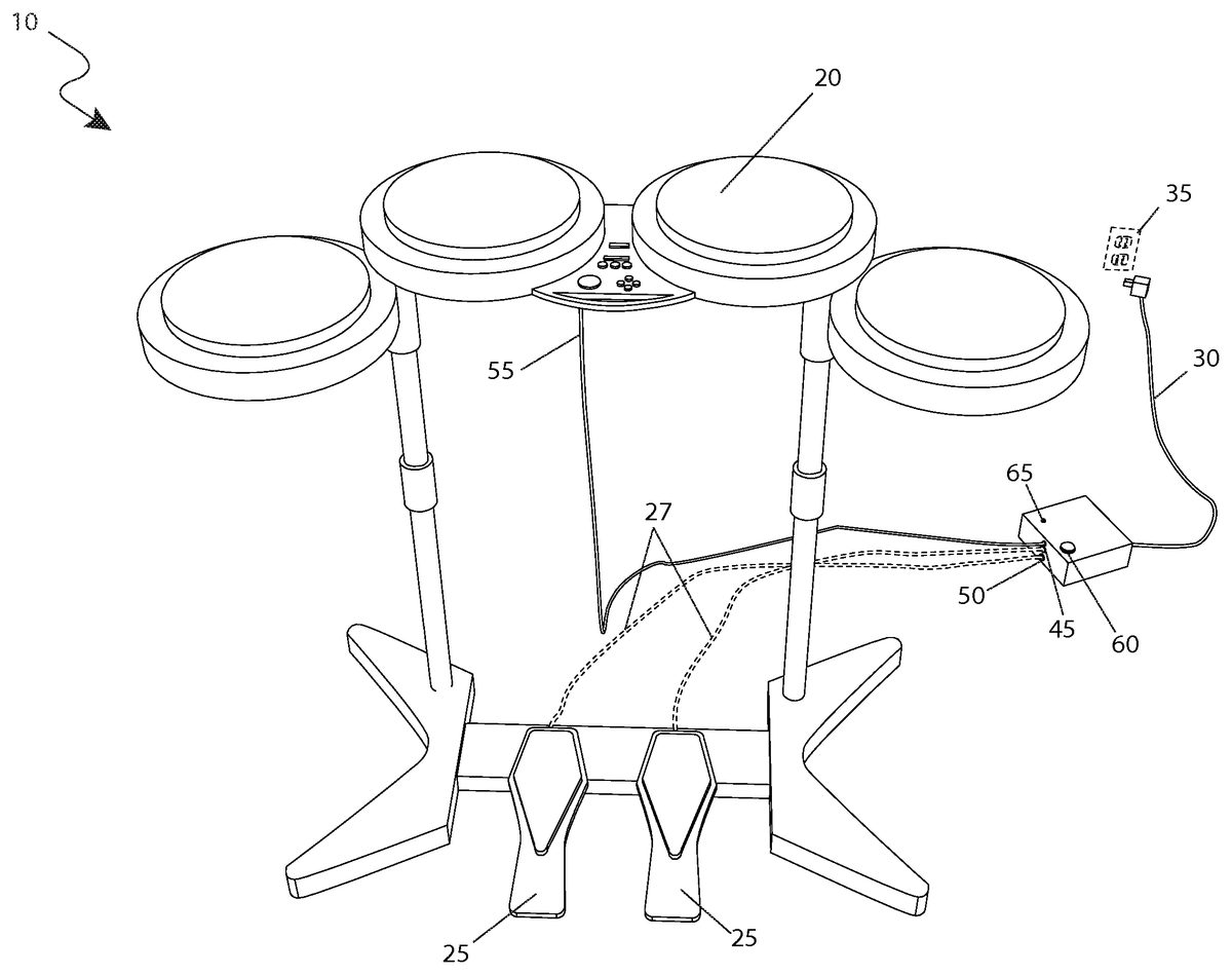
The present invention describes a dual pedal for interface for a video game system (herein described as the “apparatus”)10, which provides an adapter for the connection of a pair of bass drum pedals25to a single drum controller20in a video game such as ROCK BAND® (video game). The apparatus10accepts connection cable27from each drum pedal25and the drum controller20accepts output cable (P3)55from said apparatus10to enable a player to utilize each said pedal25during playing of the video game.
Referring now toFIG. 1, an isometric view of the apparatus10, according to the preferred embodiment of the present invention, is disclosed. The functional components of the apparatus10are provided within an enclosure15. The overall size of the enclosure15is approximately one-and one-half (1½) inches tall, four (4) inches wide and one-and-one-half (1½) inches deep. The enclosure15houses the necessary discrete components and associated circuitry to provide the necessary functionality to the apparatus10. While the present invention depicts the enclosure15as a separate device to allow for adaptation to an existing drum controller20, future versions of the present invention could be built into either the drum controller20or one (1) of the two (2) foot pedals25as part of an original equipment manufacturing configuration. As such, the enclosure15should not be interpreted as a limiting factor of the present invention. A power cord (P1)30is used to connect the apparatus10to a suitable source of electric power as provided through a 120 VAC power outlet35via a disconnect plug (P2)40. The foot pedals25are connected into a first signal jack (J1)45and a second signal jack (J2)50respectively on the enclosure15via their existing foot pedal output cables27while an output cable (P3)55is used to connect the output signal from the apparatus10to the drum controller20. The apparatus10produces an instantaneous switch closure at the instant of either switch closure from the foot pedals25. The closure immediately opens back up again regardless of whether or not the foot pedals25was released. In such a manner the other foot pedal25can immediately issue a closure command without waiting for the prior engaged foot pedal25to be released. Such a feature eliminates the collision and cancellation effects associated with simply combining the pedal closures in parallel. Thus, a player can generate a greater number of bass drum pedal actuations in a given period of time by using both feet. Additionally, such features add to the excitement of the game and allow for higher scores.
Referring next toFIG. 2, an end view of the apparatus10, according to the preferred embodiment of the present invention is depicted. This view more clearly shows the power cord (P1)30connected to the enclosure15via the disconnect plug (P2)40. The 120 VAC power outlet35allows for the continuous operation of the apparatus10without usage of internal battery (B1)57(seeFIG. 4) thus allowing basically unlimited operational time. Since the operation of the gaming system associated with the drum controller20requires the presence of conventional AC electrical power as provided by the 120 VAC power outlet35, the operation of the apparatus10is aligned in the same manner. The internal battery (B1)57is disconnected from the circuit via a top mounted battery power switch (S1)60. Thus for operation via a 120 VAC power outlet35(as seen inFIG. 1), the battery power switch (S1)60is left in an off state and the operation of the apparatus10is controlled by simply plugging the power cord (P1)30in and out of the 120 VAC power outlet35. It can be left plugged in at all times due to the low power consumption of the apparatus10. To operate the apparatus10on its internal battery (B1), the apparatus10is left unplugged from the 120 VAC power outlet35, and the battery power switch (S1)60turned on. It is turned off when utilization of the apparatus10is complete to conserve battery power.
Referring now, toFIG. 3, an opposite end view of the apparatus10, according to the preferred embodiment of the present invention is shown. This figure more clearly depicts the first signal jack (J1)45and the second signal jack (J2)50located on the face of the enclosure15along with the output cable (P3)55leaving the enclosure15. The first signal jack (J1)45and the second signal jack (J2)50are comprised of a standard eighth-inch (⅛) mono plug design such that it can connect to standard foot pedals25and standard drum controller20without customization. The battery power switch (S1)60is also visible on the top of the enclosure15. Also visible is a light-emitting diode (LED) (D4)65to indicate operation of the apparatus10and help alert the player to turn off said apparatus10when utilization is no longer needed.
Referring next toFIG. 4, an electrical schematic diagram of the apparatus10, according to the preferred embodiment of the present invention is disclosed. Electrical power is introduced to the apparatus10via the power cord (P1)30and the disconnect plug (P2)40as shown into a transformer (T1)70. The resultant AC power is converted to DC by a first integrated circuit (U1)75. Further regulation and filtering of the power is provided by a second integrated circuit (U2)80and a first transistor (Q1)85. This resultant power is then sent to a third integrated circuit (U3)90which is also supplied power via the internal battery (B1)57through the battery power switch (S1)60. The resultant power from the third integrated circuit (U3)90is then delivered to the light-emitting diode (LED) (D4)65to indicate operation as well as to a fourth integrated circuit (U4)95. The first signal jack (J1)45and the second signal jack (J2)50provide trigger inputs to the fourth integrated circuit (U4)95. Various values of related circuit components control the time duration and cycle times. The resultant output is then directed through a second transistor (Q2)100which drives the coil of a mechanical relay (K1)105. The output contacts of the mechanical relay (K1)105are then directed through the output cable (P3)55which are used to trigger the drum controller20(as shown inFIG. 1). Said description is an overview of circuit operation. Other components not described serve related functions associated with the above description and will be readily discernable to those skilled in the art. Further description of all circuit components will be provided herein below.
Referring finally toFIG. 5, a chart depicting the parts list of the electronic components as used with the apparatus10is depicted. Said description can be related to circuit designations as provided inFIG. 4with corresponding representation made to certain specific components in other figures. Exact part numbers and values serve to represent circuit operation and are not intended to limit or exclude other specific parts or values which may work equally as well.
It is envisioned that other styles and configurations of the present invention can be easily incorporated into the teachings of the present invention, and only one particular configuration shall be shown and described for purposes of clarity and disclosure and not by way of limitation of scope.
The preferred embodiment of the present invention can be utilized by the common player in a simple and effortless manner with little or no training. After initial purchase or acquisition of the apparatus10, it would be installed as indicated inFIG. 1.
The method of installing and utilizing the apparatus10may be achieved by performing the following steps: acquiring the apparatus10; activating the apparatus10via plugging in the power cord (P1)30into a 120 VAC power outlet35or operating the apparatus10with the internal battery (B1)57and depressing the battery power switch (S1)60; plugging up to two (2) foot pedals25into a respective jack (J1, J2)45,50; plugging the output cable (P3)55into the drum controller20; placing each foot upon a foot pedal25; utilizing either foot pedal25to perform an action which pertains to the game being played; deactivating the apparatus10via disconnecting the power cord (P1)30from the 120 VAC power outlet35or depressing the battery power switch (S1)60; and, utilizing the apparatus10as desired.
The foregoing descriptions of specific embodiments of the present invention have been presented for purposes of illustration and description. They are not intended to be exhaustive or to limit the invention and method of use to the precise forms disclosed. Obviously many modifications and variations are possible in light of the above teaching. The embodiment was chosen and described in order to best explain the principles of the invention and its practical application, and to thereby enable others skilled in the art to best utilize the invention and various embodiments with various modifications as are suited to the particular use contemplated. It is understood that various omissions or substitutions of equivalents are contemplated as circumstance may suggest or render expedient, but is intended to cover the application or implementation without departing from the spirit or scope of the claims of the present invention.
Claims
- A dual pedal interface for connecting two drum pedal inputs into a single output for a video game system, comprising: a first bass drum pedal, comprising a first electrical connection cable;a second bass drum pedal, comprising a second electrical connection cable;an adapter in electrical communication with said first and said second connection cable;an electrical output cable in electrical communication between said adapter and a drum controller input of said video game system;wherein said first connection cable of said first drum bass pedal provides a first input signal to said adapter;wherein said second connection cable of said second drum bass pedal provides a second input signal to said adapter;wherein said adapter is in electrical communication with a power source;wherein said adapter alters each said first input signal and said second input signal to an output signal;wherein said output signal is transmitted to said drum controller input of said video game system;wherein said adapter further comprises an enclosure further comprising: an internal battery;a battery power switch in electrical communication with said internal battery mounted on an exterior surface of said enclosure;a disconnect plug in electrical communication with a power cord electrically connected to said power source, said disconnect plug extending outward from said enclosure;a first integrated circuit in electrical communication with said disconnect plug;a second integrated circuit in electrical communication with said first integrated circuit;a first transistor in electrical communication with said second integrated circuit;a third integrated circuit in electrical communication with said second integrated circuit and said battery power switch;an indicating light in electrical communication with said third integrated circuit mounted adjacent to said battery power switch;a fourth integrated circuit in electrical communication with said third integrated circuit;a first signal jack in electrical communication between a first electrical connection cable associated with said first drum bass pedal and said fourth integrated circuit, said first signal jack located on an exterior surface of said enclosure;a second signal jack in electrical communication between a second electrical connection cable associated with said second drum bass pedal and said fourth integrated circuit, said second signal jack located on an exterior surface of said enclosure;a second transistor in electrical communication with said fourth integrated circuit;and, a relay in electrical communication between said second transistor and said output cable;wherein said first integrated circuit converts AC from said power cord to DC;wherein said second integrated circuit and said first transistor regulates and filters said DC;wherein said battery power switch disconnects said internal battery from said third integrated circuit;wherein said first signal jack provides said first input signal to said fourth integrated circuit;wherein said second signal jack provides said second input signal to said fourth integrated circuit;wherein said fourth integrated signal transfers said first and said second input signal into said output signal;wherein said second transistor drives said relay to contact said output cable, thereby transmitting said output signal to said output cable;and, wherein said first signal jack and said second signal jack each comprise an ⅛ inch mono plug.
- The dual pedal interface of claim 1 , wherein said adapter produces an instantaneous switch closure at an instant of either switch closure from said first or second drum bass pedal, said instantaneous switch closure immediately opens back up again regardless of whether said first or said second drum bass pedal was released;and, wherein said adapter enables an opposite drum bass pedal to immediately issue a closure command without waiting for a prior drum bass pedal to be released, thereby eliminating collision and cancellation effects associated with combining said switch closures in parallel so a user can generate a greater number of bass drum pedal actuations in a given period of time by using both feet.
- The dual pedal interface of claim 2 , wherein said adapter is adapted for use with a drum controller associated with a video game of a video game system.
- The dual pedal interface of claim 3 , wherein said electrical outlet cable, said first signal jack, and said second signal jack are located on a side wall of said enclosure adjacent to each other.
- The dual pedal interface of claim 4 , wherein said disconnect plug is located opposite said first signal jack, and said second signal jack.
- The dual pedal interface of claim 5 , wherein said battery power switch and said indicating light is located on a top wall of said enclosure.
- The dual pedal interface of claim 3 , wherein said battery power switch and said indicating light is located on a top wall of said enclosure.
- A dual pedal interface for connecting two drum pedal inputs into a single output for a video game system, comprising: a drum controller in electrical communication with said video game system, comprising: a first bass drum pedal, comprising a first electrical connection cable;a second bass drum pedal, comprising a second electrical connection cable;and, a drum controller input;an adapter in electrical communication with said first and second connection cable;an electrical output cable in electrical communication between said adapter and said drum controller input;wherein said first connection cable of said first drum bass pedal provides a first input signal to said adapter;wherein said second connection cable of said second drum bass pedal provides a second input signal to said adapter;wherein said adapter is in electrical communication with a power source;wherein said adapter alters each said first input signal and said second input signal to an output signal;wherein said output signal is transmitted to said drum controller input;wherein said adapter further comprises an enclosure further comprising: an internal battery;a battery power switch in electrical communication with said internal battery mounted on an exterior surface of said enclosure;a disconnect plug in electrical communication with a power cord electrically connected to said power source, said disconnect plug extending outward from said enclosure;a first integrated circuit in electrical communication with said disconnect plug;a second integrated circuit in electrical communication with said first integrated circuit;a first transistor in electrical communication with said second integrated circuit;a third integrated circuit in electrical communication with said second integrated circuit and said battery power switch;an indicating light in electrical communication with said third integrated circuit mounted adjacent to said battery power switch;a fourth integrated circuit in electrical communication with said third integrated circuit;a first signal jack in electrical communication between a first electrical connection cable associated with said first drum bass pedal and said fourth integrated circuit, said first signal jack located on an exterior surface of said enclosure;a second signal jack in electrical communication between a second electrical connection cable associated with said second drum bass pedal and said fourth integrated circuit, said second signal jack located on an exterior surface of said enclosure;a second transistor in electrical communication with said fourth integrated circuit;and, a relay in electrical communication between said second transistor and said output cable;wherein said first integrated circuit converts AC from said power cord to DC;wherein said second integrated circuit and said first transistor regulates and filters said DC;wherein said battery power switch disconnects said internal battery from said third integrated circuit;wherein said first signal jack provides said first input signal to said fourth integrated circuit;wherein said second signal jack provides said second input signal to said fourth integrated circuit;wherein said fourth integrated signal transfers said first and said second input signal into said output signal;wherein said second transistor drives said relay to contact said output cable, thereby transmitting said output signal to said output cable and to said drum controller input;wherein said first signal jack and said second signal jack each comprise an ⅛ inch mono plug.
- The dual pedal interface of claim 8 , wherein said adapter produces an instantaneous switch closure at an instant of either switch closure from said first or second drum bass pedal, said instantaneous switch closure immediately opens back up again regardless of whether said first or said second drum bass pedal was released;and, wherein said adapter enables an opposite drum bass pedal to immediately issue a closure command without waiting for a prior drum bass pedal to be released, thereby eliminating collision and cancellation effects associated with combining said switch closures in parallel so a user can generate a greater number of bass drum pedal actuations in a given period of time by using both feet.
- The dual pedal interface of claim 9 , wherein said adapter is adapted for use with a video game of a video game system.
- The dual pedal interface of claim 10 , wherein said electrical outlet cable, said first signal jack, and said second signal jack are located on a side wall of said enclosure adjacent to each other.
- The dual pedal interface of claim 11 , wherein said disconnect plug is located opposite said first signal jack, and said second signal jack.
- The dual pedal interface of claim 10 , wherein said battery power switch and said indicating light is located on a top wall of said enclosure.
- The dual pedal interface of claim 12 , wherein said battery power switch and said indicating light is located on a top wall of said enclosure.
Disclaimer: Data collected from the USPTO and may be malformed, incomplete, and/or otherwise inaccurate.