U.S. Pat. No. 8,308,558
UNIVERSAL TACTILE FEEDBACK SYSTEM FOR COMPUTER VIDEO GAMES AND SIMULATIONS
Issue DateApril 17, 2008
Illustrative Figure
Abstract
A universal tactile feedback system for computer and video game systems is disclosed which provides real time tactile feedback to enhance a user's experience while interacting with a computer/video game or simulation. The tactile feedback system operates both in host-independent and host-dependent modes, thereby allowing the system to function even when no accommodation is provided by the game or simulation system that is being used. The host-independent mode is responsive to the audio signal that is typically generated by a computer or video game system while it is executing a game or simulation. The host-dependent mode is responsive to control commands specifically generated by a computer or video game system while it is executing a game or simulation. The tactile feedback system then creates tactile sensations primarily via controller-based tactile sensation generators, such that the user feels physical sensations corresponding to events occurring within the game or simulation in real time.
Description
To facilitate understanding, identical reference numerals have been used, where possible, to designate identical elements that are common to the figures. DETAILED DESCRIPTION FIG. 1depicts a high level block diagram of a tactile feedback system100interfacing with a computer system or video game console102(hereinafter host computer). The host computer102is connected to the tactile feedback system100by electrical connections103and104which may carry analog or digital signals respectively. In fact, signals from the host computer can be passed to the tactile feedback system using other types of communication channels106, e.g., channels that employ infrared radiation, radio wave or sound wave. If these communication channels are used, then the corresponding receivers must be implemented on the tactile feedback system, e.g., RF receiver, IR receiver or a microphone. Thus, it should be understood that the configuration of having the host computer102coupled to the tactile feedback system100is only illustrative and the present invention is not so limited. Namely, the host computer102can be implemented as any device that is capable of sending the necessary control signals (e.g., a speaker broadcasting the sounds from a video game), such that the tactile feedback system is capable of operating one or more tactile sensation generators. The tactile feedback system100comprises a tactile feedback controller110and one or more tactile sensation generators120. In the preferred embodiment, the tactile feedback controller110is connected by power distribution cables116to multiple independent tactile sensation generators120. However, the present invention can be modified such that only control signals are forwarded to the tactile sensation generators, where each generator is able to be activated under its own power source. The tactile feedback controller110comprises a host independent portion112and a host dependent portion114. Namely, the host-independent portion allows the tactile feedback controller110to interpret the audio signals from a video game to generate the control signals for the tactile sensation generators. Under this mode of ...
To facilitate understanding, identical reference numerals have been used, where possible, to designate identical elements that are common to the figures.
DETAILED DESCRIPTION
FIG. 1depicts a high level block diagram of a tactile feedback system100interfacing with a computer system or video game console102(hereinafter host computer). The host computer102is connected to the tactile feedback system100by electrical connections103and104which may carry analog or digital signals respectively. In fact, signals from the host computer can be passed to the tactile feedback system using other types of communication channels106, e.g., channels that employ infrared radiation, radio wave or sound wave. If these communication channels are used, then the corresponding receivers must be implemented on the tactile feedback system, e.g., RF receiver, IR receiver or a microphone.
Thus, it should be understood that the configuration of having the host computer102coupled to the tactile feedback system100is only illustrative and the present invention is not so limited. Namely, the host computer102can be implemented as any device that is capable of sending the necessary control signals (e.g., a speaker broadcasting the sounds from a video game), such that the tactile feedback system is capable of operating one or more tactile sensation generators.
The tactile feedback system100comprises a tactile feedback controller110and one or more tactile sensation generators120. In the preferred embodiment, the tactile feedback controller110is connected by power distribution cables116to multiple independent tactile sensation generators120. However, the present invention can be modified such that only control signals are forwarded to the tactile sensation generators, where each generator is able to be activated under its own power source.
The tactile feedback controller110comprises a host independent portion112and a host dependent portion114. Namely, the host-independent portion allows the tactile feedback controller110to interpret the audio signals from a video game to generate the control signals for the tactile sensation generators. Under this mode of operation, the tactile feedback controller is able to use the audio signals to properly decipher the actions of the video game, independent of any control signals from the video game.
In contrast, the host-dependent portion allows the tactile feedback controller110to receive and process the control signals from a host computer102to generate the control signals for the tactile sensation generators. Namely, the control signals from the host computer102is designed specifically for the tactile feedback system.
In the preferred embodiment, electrical connection103represents the audio cable (stereo or mono) that carries the analog audio signal produced by the host computer102. More specifically, the host computer102has one of its audio output ports, e.g., an amplified or line-level ⅛ inch stereo output connector, connected via line103to an input port118of the tactile feedback controller110.
Similarly, electrical connection104represents a cable that carries the digital signal produced by the host computer102to an input port119of the tactile feedback controller110. In this preferred embodiment, the digital cable104is a parallel cable, e.g., a DB25 to DB25 “straight through” male to male cable. However, it should be understood that the present invention can be implemented with any type of digital cables, port configurations and various other transmission protocols (such as RS-232 DB9 serial or USB universal serial bus, PCMCIA card connector and cable, coaxial cable, and the like).
Furthermore, a pass through port117is coupled to port119to allow the signals carried on the electrical connection104to pass through port119. This pass through port allows multiple tactile feedback controllers110to be daisy chained to support additional tactile sensation generators. This pass through port also serves to pass non-tactile sensation related signals to other peripherals, e.g., a printer.
In the preferred embodiment, twelve (12) pins on the electrical connection104are employed to communicate with the tactile feedback controller110. Namely, the present invention employs a 12-bit bus for communication with a communication format having a 4-bit control word and an 8-bit data word. Throughout this disclosure, the physical locations for the 4-bit control word and 8-bit data word on line104are referred to as PORT A and PORT B, respectively.
It should be understood that although the present invention employs a 12-bit bus for communication, buses of any size can be implemented. Generally, the selection of a communication protocol and bus size is governed by the requirements of a particular application. For example, a more powerful microcontroller may have sufficient I/O pins to allow a communication format greater than 12 bits.
Furthermore, bidirectional communication can also be implemented between the host computer102and the tactile feedback controller110. Such bidirectional communication would allow the tactile feedback controller110the ability to transmit internal status, verification and operating data to the host computer system102.
The present 12-bit communication bus is used for two separate and distinct types of communication: sending batch data transmissions and sending host-dependent direct digital control signals. Batch data transmissions allow the host computer102to send configuration data in real time to the tactile feedback controller110. These batch data transmissions may include such information as default settings, user preferences, device configurations, application specific audio analysis parameters, system analysis display modes, which are described in detail below.
The other type of communication that occurs over the 12-bit bus (comprised of 4-bit PORT A and 8-bit PORT B) is the transmission of control signals necessary to support the host-dependent mode of operation. If the software application executing on the host computer102supports this mode of operation, the user can place the tactile feedback controller110in the host-dependent mode by flipping a mode select switch. In this mode of operation, control signals necessary to operate the various tactile sensation generators are derived from the control signals received from the host computer102.
Alternatively, the tactile feedback controller110can be implemented such that it is able to automatically select its optimal mode of operation, e.g., the presence or absence of a start code from the host computer or the detection of a valid signal by the host independent section112. In the preferred embodiment, a mode select toggle switch is implemented to select one of two possible positions, e.g., host-independent mode or host-dependent mode. This switch can be activated at any time by a user to select the desired mode, even while the system is in use.
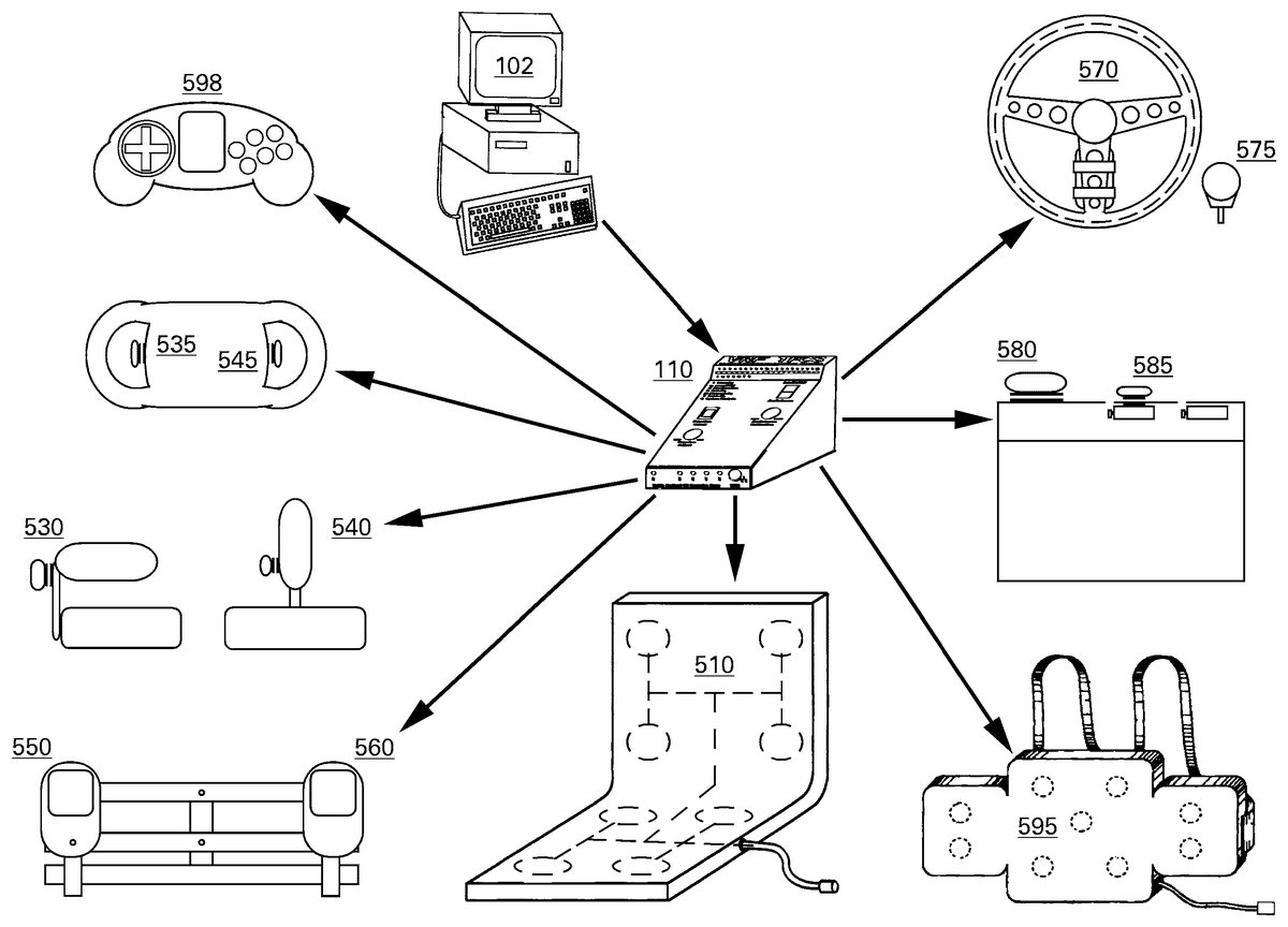
FIG. 2depicts an illustrative configuration of the present tactile feedback system100. Namely, a host computer102is coupled to the tactile feedback controller110which, in turn, is coupled to one or more tactile sensation generators120. Within the scope of the present invention, the tactile sensation generators may include a tactile sensation seating unit510, a tactile sensation chest harness520, a tactile sensation enhanced throttle530, a tactile sensation enhanced joystick540, a tactile sensation enhanced flight yolk with a left handle535and a right handle545, tactile sensation enhanced rudder pedals with a left pedal550and a right pedal560, a tactile sensation enhanced steering wheel570, a tactile sensation enhanced shift knob575, tactile sensation enhanced driving pedals585extending from a pedal base unit580, a vest-based tactile sensation generator595, and a tactile sensation enhanced hand-held game controller598. Each of these tactile sensation generators is discussed later in this disclosure.
FIG. 3depicts a block diagram of the present tactile feedback controller110. More specifically, the tactile feedback controller comprises a plurality of ports117-119, an audio signal preprocessing section310, a microcontroller320, transistor switch circuits350, a plurality of switches360, and a display370. The microcontroller320is illustrated as having one or more analog-to-digital converters330, memories (random access memory342and read only memory344) and a processor340.
Referring toFIG. 3, host independent section112and host dependent section114are illustrated in dashed boxes. Since these sections share common resources, the dashed boxes serve to illustrate the components that are implemented within each section. More specifically, in the host-independent mode of operation, the audio signal is received into the tactile feedback controller via port118. The audio signal is initially processed by an audio signal pre-processing section310. This section serves to filter and separate the audio signal into one or more filtered audio signals that are more amenable to manipulation by the microcontroller320.
The analog audio signals leaving pre-processing section310are then sampled by analog-to-digital converters (ADCs)330to produce digital signals that are processed and analyzed by the processor340to generate the control signals for the tactile sensation generators. The processing of the audio signals are generally performed under the control of the microcontroller320using the appropriate software application residing in the ROM344.
In the host-dependent mode of operation, the digital signals are received into the tactile feedback controller110via port119. Specifically, port119comprises a 4-bit input port and an 8-bit input port which are designed to receive control and data signals from the host computer102. For simplicity, the 4-bit port is referred to as PORT A, and the 8-bit port is referred to as PORT B. If a valid 12-bit signal is received by PORT A and PORT B, then the 12-bit signal is analyzed by the processor340to generate the control signals for the tactile sensation generators.
However, if the combined 12-bit signal indicates a batch data transmission, then the microcontroller320is alerted that one or more configuration functions are being requested by a user. Various configuration functions are described later in this disclosure.
Next, control signals for the tactile sensation generator (derived from either the host-independent mode or the host-dependent mode), are converted into multiple independent pulse width modulation (PWM) control signals that are sent via TTL circuit lines to the transistor switch circuits350, to drive one or more tactile sensation generators120that are connected to the tactile feedback controller110.
Additionally, a display370(20 LEDs) is coupled to the microcontroller320for providing a visual aid to a user who is performing a configuration function or who is simply monitoring the status of the tactile feedback controller110. More specifically, the display allows the user to see the internal activity of the tactile feedback controller110, by activating the LEDs in a manner that illustrates the status of many different types of information. This information may include real time audio sampling data, real time audio analysis data, direct digital signal control data, and various parameters that control aspects of the tactile feedback generated by the tactile feedback controller110. Although the preferred embodiment has implemented this display as a horizontal strip of 20 rectangular LEDs, this display can be implemented in many different ways or not at all.
For example, an alphanumeric liquid crystal display (LCD) having two (2) display lines of 12 characters can be used to display a parameter name on the first LCD display line, and the parameter's numerical value on the second LCD display line, followed by some unit label (e.g., seconds, percent, amplification, reduction, and the like, as necessary). Furthermore, simple messages such as “YES”, “NO”, and other words can also be displayed on such an alphanumeric display, when appropriate.
Finally, tactile feedback controller110further incorporates a plurality of switches360, which include a mode select switch, a function select switch, and a rotary encoder switch. The functions of these switches are described in greater detail below. Although the present invention utilizes three hardware switches, those skilled in the art will realized that any number of switches, or no switches at all, can be implemented in the present invention.
FIG. 4depicts a block diagram of the audio signal preprocessing section310. The audio signal preprocessing section310comprises a front end circuit410, a variable gain preamplifier420, and three separate audio filters/buffers430-450.
More specifically, a stereo audio signal from the host computer102enters the front-end circuit410within which the stereo audio signal is combined into a composite signal. Namely, host computer102sends an audio signal via audio cable103, comprising a left audio channel and a right audio channel. The front end circuit410contains a mixer for combining both channels of a stereophonic audio signal to form a composite audio signal, a high pass filter for limiting noise that is below the audio band, e.g., lower than 20 Hz, and a diode signal limiter for limiting (clipping) the amplitude of the input signal to protect the audio signal preprocessing section310from overly powerful audio signal inputs. A detail circuit diagram of the front end circuit410is depicted inFIG. 5.
The output from the front end circuit410then enters a variable gain preamplifier420. The variable gain preamplifier420establishes the dynamic range of the analog audio signal preprocessing section310. Namely, the tactile feedback controller110provides the user with a calibration knob that varies the resistance provided by a potentiometer, which, in turn, determines the gain of the variable gain preamplifier420. For example, if the gain of the variable gain preamplifier420is set too high, the audio signal has a tendency to saturate and, consequently, the usefulness of the audio signal is compromised. Alternatively, if the gain of the variable gain preamplifier420is set too low, the audio signal does not have sufficient dynamic range to provide useful data to the host-independent section112. A detail circuit diagram of the variable gain preamplifier420is depicted inFIG. 6.
FIG. 6illustrates a switch SW5to address audio output signal of different strengths. Namely, a host computer102may typically produce an audio signal in two different types of audio output signal strengths, i.e., amplified “speaker” outputs and non-amplified “line level” outputs. Most audio output cards allow a computer user to select a signal strength that is optimal for his or her audio equipment. However, older audio output cards often provided only amplified audio output signal strength on a single connector. Amplified “speaker” audio output typically provides 4 watts of amplification at 8 ohms resistance. In cases where the host computer102only has one audio output jack, the single output can be split via a readily available Y-type adapter that will provide two output jacks from the single pre-existing jack. Thus, the Y-adapter provides one connector for the user's speakers, and a second connector for the user to couple the host computer to the tactile feedback controller110.
The second type of audio output signal strength is non-amplified “line level” audio output, which is commonly used by stereo equipment. This audio output signal strength is typically meant for an external stereo amplifier, such that the audio output of the host computer102can be broadcast from the user's home stereo system. Similarly, the line level output jack can also be split, when necessary, with a Y-type adapter.
In order to accommodate these different audio signal strengths, the tactile feedback controller110provides a small two position switch (depicted as SW5inFIG. 6), that changes the gain of the variable gain preamplifier420as appropriate for the audio output signal strength provided by the host computer102. This small switch is labeled SPKR and LINE, and is set by the user to match the signal provided by the audio output jack on the host computer102.
In the SPKR position, the switch is closed, which effectively bypasses a gain inducing resistor. (R10ofFIG. 6) within the variable gain preamplifier420, thereby reducing the range of amplification available to the variable gain preamplifier420. In the LINE position, the switch is open, which effectively incorporates the otherwise bypassed gain inducing resistor (R10ofFIG. 6), thereby increasing the range of amplification available to the variable gain preamplifier420. In this manner, the variable gain preamplifier420can maintain a useful range of amplification that is appropriate for the SPKR or LINE signal strength. Thus, without this feature, the variable gain preamplifier420would often be at its limits, e.g., at a low amplification setting when used with an amplified SPKR signal, and at a high amplification setting when used with a non-amplified LINE signal, but rarely in the middle of its effective range.
Referring back toFIG. 4, the variable gain preamplifier420simultaneously feeds, via line145, to three separate audio filters/peak hold buffers430-450that split the resulting audio signal into independent bass, midrange, and treble analog audio information streams. Namely, the original stereo audio signal exits the audio signal preprocessing section310as three independent audio signals, composed of an analog bass signal on line152, an analog midrange signal on line162, and an analog treble signal on line172. Detail circuit diagrams of the treble audio filter and peak buffer450, midrange audio filter and peak buffer440, and the bass audio filter and peak buffer430, are depicted inFIGS. 7-9respectively.
The bass audio filter and peak hold buffer430uses a low pass filter that passes low frequencies, e.g., below 338 Hz. The treble audio filter and peak hold buffer450uses a high pass filter that passes high frequencies, e.g., above 1.6 KHz. In the preferred embodiment, the midrange audio filter and peak hold buffer440uses a difference amplifier that removes the combined signals of the bass and treble audio filters from the signal that exits the variable gain preamplifier420. Namely, the midrange filter yields an audio signal that is essentially what remains after the bass and treble frequencies have been isolated, combined, and then subtracted from the main signal. This reduces the overlapping roll-off that occurs as the frequency responses of the high and low pass filters fade out and extend beyond their respective frequency cutoff properties. This ensures that the bass430, midrange440, and treble450filters will yield independent signals that do not suffer from too much frequency intersection.
Alternatively, a bandpass filter could be used in place of the difference amplifier, in order to specifically pass a tunable band illustratively centered at 1.2 KHz. It should be understood that the present invention can be implemented using other filter designs.
Each of the filtered bass, midrange, and treble signals enters a peak buffer, which allows the respective filtered audio signals to stabilize by charging a capacitor in each buffer, that then discharges at a relatively rapid rate. It is important for the three analog to digital converters330on the microcontroller320to sample stable signals, but the primary purpose of these buffers is not to control the decay rate of the audio signal. The decay rate of each of the filtered audio signals is determined by its own variable decay parameter that is used by the processor340in processing the sampled audio signal data. Thus, upon exiting the audio filters and peak hold buffers, each filtered audio stream is fed into its own analog to digital converter (ADC)330.
FIG. 10illustrates a flow chart of a method1000for generating control signals for tactile sensation generators under a host independent mode or a host dependent mode of operation. Method1000starts in step1005and proceeds to step1010, where the tactile feedback controller110is initialized. The initialization step executes a power on reset sequence for the microcontroller320which may include a RAM/ROM and I/O hardware initialization. Namely, the integrity of the RAM is verified and default information, such as stored variables and various tables, are loaded from the ROM and into the RAM of the microcontroller320.
In step1020, method1000queries whether the user wishes to invoke a special demonstration mode of the tactile feedback system. If the query is positively answered, then method1000proceeds to step1025, where a demonstration is presented to the user where various tactile sensation generators (including the LED display) are activated in a predetermined sequence. If the query is negatively answered then method1000proceeds to step1030, where the method1000queries whether configuration command is detected.
Generally, the demonstration mode is designed to be skipped, by default, unless the user performs the specific action that requests it. More specifically, the present invention checks to see if a specific button, the “Function Select” switch, is depressed by the user during the power on reset sequence. In fact, the stored demonstration in the ROM can also be used as a manufacturing test to verify newly manufactured tactile feedback controllers. By implementing a predetermined sequence that is designed to exercise all features of the tactile feedback controller and to activate every available tactile sensation generators, the demonstration sequence can be used to detect malfunction. The demonstration lasts approximately 90 seconds.
Returning to step1030, method1000queries whether a configuration command is detected. More specifically, in the present invention, configuration commands are provided in the form of a batch data transmission. Batch data transmissions carry data that allows various operational parameters of the system to be reconfigured in real time. These batch data transmissions begin with a multi-stage trigger (code), which alternatively strobes back and forth between two predetermined values. If the data present on the input ports of the tactile feedback controller110is identified as a trigger strobe for a batch data transmission, then method1000proceeds to step1035where the configuration commands/data within the batch data transmission are executed. Examples of functions that can be executed at this step include: 1) changing display modes of various internal variables on the LED display (See Appendix A for a list of such display modes), 2) setting various tactile sensation generator power output parameters, and 3) setting any of the audio postprocessing parameters at discussed below in step1065. Once all the configuration commands/data are serviced by the tactile feedback controller110, method1000proceeds to step1040.
In step1040, method1000queries whether host dependent mode is selected. If the query is negatively answered, then method1000proceeds to step1065, where audio signal postprocessing is executed. If the query is affirmatively answered, then method1000proceeds to step1050, where method1000determines if digital control is active.
Namely, if the tactile feedback system is set in the host-independent audio analysis mode, method1000executes the digital audio post processing procedure. If the tactile feedback system is not set in the host-independent audio analysis mode, then the system is in the host-dependent direct control mode by default.
In step1050, method1000queries whether digital control has been previously activated since the last power on reset. Namely, method1000determines if a specific start code has been received at PORT A and PORT B. The specific start code indicates that a software application on the host computer102is attempting to send digital signals to the tactile feedback controller110. More importantly, the initial reception of this start code would have initialized the host dependent section114of the tactile feedback controller110. Such initialization places the host dependent section114in condition to receive control signals from the host computer. This start code is employed to keep the direct digital control mode from erroneously reacting to data on the parallel printer port bus that may not be intended for the tactile feedback controller110. This may occur if devices other than tactile feedback controllers110are daisy chained along the parallel bus, such as printers, tape back up drives, portable SCSI devices, and so on. If the query is affirmatively answered, i.e., direct digital control was previously activated, method1000proceeds to step1060where direct control signal postprocessing is executed. If the query is negatively answered, method1000proceeds to step1055.
In step1055, method1000queries whether a start code has been received and whether initialization is presently in progress. Namely, it is possible that although host dependent section114is not in condition to receive control signals from the host computer at step1050, but it may be in active condition pending the completion of initialization that is currently in progress. If the query is affirmatively answered, then step1055proceeds to step1060. In other words, method1000checks if the previously read data from the digital input ports represents a predetermined initialization and reset code. If so, direct digital control is activated, and method1000proceeds to step1060where the digital control signal postprocessing is executed.
If the query is negatively answered, then step1055proceeds to step1050and waits for the activation of the host dependent section114. Namely, if the appropriate initialization and reset code is not present, digital control remains inactive, and returns to step1050.
It should be noted that step1060and can be called to service new data on the digital input ports by two primary means: polling the input ports for new data, or responding to hardware interrupts generated by the microcontroller320as determined by the capability of the selected microcontroller. This polling and/or interrupt response occurs to insure that no vital digital control signal data is missed.
In step1070, method1000receives either postprocessed audio signals from step1065or postprocessed direct digital signals from step1060. Using these postprocessed signals, method1000generates the necessary and appropriate control signals for the various tactile sensation generators120. It should be understood that method1000will continue to operate until the tactile feedback controller110is turned off.
FIG. 11is a flow chart for the method1065of postprocessing the audio signals, i.e., the digital audio post-processing step1065ofFIG. 10. Method1065starts in step1105and proceeds to step1110where the raw audio signals on paths152,162and172are digitized as illustrated inFIG. 4above. Namely, analog to digital converters (ADC)330produces a set of three raw digital signals, BASS audio signal, MIDRANGE audio signal and TREBLE audio signal.
In step1120, the set of three raw digital signals, BASS audio signal, MIDRANGE audio signal and TREBLE audio signal are respectively processed with a set of BASS, MIDRANGE and TREBLE audio analysis parameters (seeFIG. 12), which yields a calculated BASS result, a calculated MIDRANGE result, and a calculated TREBLE result.
In step1130, these three individual calculated audio results are combined to yield a single host-independent master control signal from audio signal postprocessing analysis, which is then placed into the internal RAM based digital control signal table (discussed below) for generating the control signals for the various tactile sensation generators. In the preferred embodiment, the calculated signals are combined by simply selecting a value corresponding to the highest value among the three calculated values. However, other methods can be employed, e.g., a weighted average calculation. Finally, in step1140, method1065ends or returns to step1070ofFIG. 10.
FIG. 12is a flow chart of a method1120for processing the raw audio signals with a plurality of audio analysis parameters. Namely, the set of three raw digital signals, BASS audio signal, MIDRANGE audio signal and TREBLE audio signal in step1110ofFIG. 11are modified in accordance with a set of audio analysis parameters. Although there are a total of 33 parameters, e.g., 11 for each audio band (BASS, MIDRANGE, and TREBLE),FIG. 12only illustrates 11 parameters since these same parameters are applied to all three raw signals, with the exception of having different audio band specific values for each raw signal. Thus, althoughFIG. 12uses the audio band specific subscripts to identify the audio band of BASS, it should be understood that the subscripts imply that BASS specific default values were employed to process the raw BASS signal. Thus, although parameters with the same name have the same function, the actual value of each parameter is individually programmable for each of the three available audio bands, and only affects the audio band to which its subscript specifically applies. Namely,FIG. 12illustrates the audio analysis parameters that are used to produce the three individual calculated audio results. It should be noted that the present invention is not limited by the number of parameters that are employed.
The process by which these parameters are applied to each raw digital audio sample begins by copying the raw digital audio samples into three individual buffers within the RAM342of the microcontroller320. These buffers are referred to as the calculated bass result, the calculated midrange result, and the calculated treble result. Each of these three buffers carries the cumulative results of the calculations that are performed as the specific parameters of each parameter set illustrated inFIG. 12are applied to change the values within the three buffers. This essentially yields three constantly changing calculated audio result buffers while the original raw digital audio samples remain unchanged. In this fashion, the original raw digital audio samples are stored and made available for later use by other calculations within the digital audio post-processing method. Ultimately, the three buffers emerge from the three audio analysis parameter sets as the final audio band specific calculated audio results.
Returning toFIG. 12, method1120starts in steps1205and proceeds to step1210where the parameter Squelch is applied to the raw signal. The SQUELCH parameter provides a means of ignoring audio signals that have an amplitude that is less than some desired threshold, e.g., 2% of the maximum signal value.
To illustrate, for an 8-bit digital audio sample, the maximum value is 255 in binary. Thus, a 2% threshold equates to approximately a value of 5 (0.02.times.255). If a raw digital sample is less than its appropriate SQUELCH parameter, the appropriate calculated result is forced to zero. If the raw digital sample is greater than or equal to its appropriate SQUELCH parameter, the appropriate calculated result is set equal to the original raw digital sample.
In step1220and1230, the next two parameters are PREAMP QUALIFIER and PREAMP MULTIPLIER, which function as a pair. These two parameters function together to provide a means of preamplifying quiet sounds by some factor, while leaving louder sounds unaffected. This is useful, for example, in helicopter simulations, where the sound of the rotor blades spinning in the background can generally impart some useful velocity or engine activity cue, but such sound is typically very quiet so as not to be overwhelming during the simulation. These two audio analysis parameters effectively allow these quiet sounds to be preamplified, such that the velocity or engine activity cue can be translated into useful tactile feedback, while not affecting louder sounds in the same manner. These two steps operate by comparing the current calculated audio result, either bass signal, midrange signal, or treble signal to its appropriate PREAMP QUALIFIER. If any given calculated audio result is higher than its appropriate PREAMP QUALIFIER, the calculated audio result is disqualified for preamplification, and its PREAMP MULTIPLIER is not implemented. However, if any given calculated audio result is lower than its appropriate PREAMP QUALIFIER, the calculated audio result is qualified for preamplification, and therefore multiplied (e.g., amplified) by its PREAMP MULTIPLIER. The result of this calculation cannot be larger than the PREAMP QUALIFIER value that qualified the multiplication in the first place. If the result of this calculation is larger than the PREAMP QUALIFIER value, the result is set equal to the PREAMP QUALIFIER value. This eliminates the possibility that quiet sounds will become over amplified.
In step1240, the next parameter is the EQUALIZER. This step allows a current calculated audio result to be reduced or amplified, e.g., equalized, by some factor. Specifically, the equalizer provides for effectively multiplying any given calculated audio result by any number between 0.00 and 8.00, with 0.03 increments. This yields approx. 32 levels of reduction from 0% to 97% of the original value in approximately 3% steps (e.g., multiplying any given calculated audio result by any number between 0.00 and 0.97). This also yields approx. 265 levels of amplification from 103% to approximately 800% of the original value in approximately 3% steps (e.g., multiplying any given calculated audio result by any number between 1.03 and 8.00 in 0.03 steps). Although this equalizer range is very effective, the present invention is not limited by any default values or how this function is mathematically or otherwise implemented, and/or to the resolution and limits of such calculations.
In step1250, the next parameter is MAXIMUM. This parameter limits the result of the EQUALIZER multiplication result to some highest allowed value, or maximum, e.g., no higher than 75% of the maximum level. The MAXIMUM parameter limits high equalization results when relatively high amplitude signals are generated by the host computer102. The MAXIMUM parameter is useful when high equalization values are used, and affected upon high amplitude audio signals.
In step1260, the next parameter is the RISE RATE. This parameter establishes a maximum allowable rise rate between two sequential audio samples. If the difference between a current digital audio sample and its corresponding prior sample is a positive value that exceeds the RISE RATE parameter, e.g., a value corresponding from 20 ms. to 2 seconds, then the RISE RATE parameter is added to the prior of the two sequential samples, and the result is used in place of the most recent calculated audio result, thereby effectively yielding a reduced rise rate, in accordance with the RISE RATE parameter.
In step1270, the next parameter is the DECAY RATE. This parameter establishes a maximum allowable decay rate between two sequential audio samples. If the difference between a prior digital audio sample and its corresponding current sample is a positive value that exceeds the DECAY RATE parameter, then the DECAY RATE parameter is subtracted from the prior of the two sequential samples, and this result is used in place of the most recent calculated audio result, thereby effectively yielding a reduced decay rate, in accordance with the DECAY RATE parameter.
In steps1280-1294, the last four parameters function together to provide a means of interpreting various audio amplitude inducing simulated events, and subsequently generating an appropriately strong tactile response. Essentially, it is very important to recognize abrupt increases in audio amplitude over some number of sequential digital audio samples. In games or simulations, any number of generally traumatic events can occur that will require a very powerful response by the tactile feedback controller110when it is operating in its host-independent audio analysis mode. For example, a simulated car being driven by the simulation user may bump another simulated car, or crash into a simulated object at a high velocity. Likewise, a simulated enemy missile or other simulated offensive/defensive weapon may strike a simulated vehicle being piloted by the simulation user. These types of simulated events, and others like them, are typically accompanied by an abrupt and varied rise in the amplitude of some appropriately provided sound effect (hereafter referred to as a “crash” event). However, this rise in audio amplitude may not inherently have enough power, and/or may not last long enough, to cause a powerfully appropriate tactile feedback event to match the simulated event.
In order to rectify this shortcoming, in steps1280and1290the next two parameters, CRASH MAGNITUDE and CRASH TIME SPAN, together allow the combined magnitude and time span of an abrupt rise in the digitally sampled audio to generate a “crash” response. The tactile feedback resulting from this “crash” response is then controlled by the last two parameters in step1292and1294, CRASH HOLD and CRASH FADEOUT. The CRASH MAGNITUDE parameter establishes the minimum rise in sampled audio amplitude that will qualify as a “crash” event. The CRASH TIME SPAN parameter establishes the maximum time allowed for an acceptable CRASH MAGNITUDE rise to develop. For example, these parameters may look for a rise in amplitude of 30% of the maximum possible amplitude, over a 0.125 second time span. Together, these two parameters across all three audio bands provide for a very powerful and versatile method of detecting events that require strong tactile feedback responses. If a sound event generates a rise in audio amplitude that exceeds the CRASH MAGNITUDE parameter within the allowed CRASH TIME SPAN, a “crash” event is triggered. In such a case, the specific calculated audio result for the audio band in which the crash event occurred is set to its highest possible value, and is not subject to limitation by the previously explained MAXIMUM parameter. This highest possible value is maintained within the appropriate calculated audio result for the time specified in the CRASH HOLD parameter, e.g., 0.25 sec. After the CRASH HOLD time expires, the CRASH FADEOUT parameter specifies the time, e.g., 0.1 sec., that it will take to decay this highest possible output down to zero. This step allows “crash” tactile feedback responses to range from hard hitting, instantly decaying jolts, to instantly peaking and slowly decaying waves. The decay in the “crash” event is preempted by new data if subsequent audio samples generate a new rise in audio amplitude. In this manner, strong tactile feedback responses can be shaped as desired, and will be divorced entirely from the inherent strength and duration of the original “crash” sound event.
Once all three calculated audio results are processed with all of their respective parameters, method1120ends in step1295or returns to step1130ofFIG. 11, where the three individual values are combined to yield a host-independent master control signal from audio analysis. In turn, this audioderived control signal is then placed into the device0“master device” entry in the internal RAM based digital control signal table for power distribution as discussed below. It should be noted that the signal residing within the “master device” entry in the internal RAM is regarded as the master control signal, regardless as to how this signal was generated. Namely, this signal can be generated by both the host mode or the host dependent mode. Thus, a signal extracted from this “master device” entry (device0) shall be referred to as the master control signal.
FIG. 13is a flow chart of a method1060for direct control signal postprocessing. Namely, it is a flow chart that illustrates the processing step of1060inFIG. 10. Method1060processes digital control signal data generated by the host computer102that is received from PORT A and PORT B in real time. This digital control signal data can be implemented in numerous ways, with each approach carrying different types of information within the transmitted data. For example, the digital control signal may be a simple, single code, that causes a course of events to occur within the microcontroller320. The digital control signal can be a set of values, which may include some tactile feedback effect identification number, and some parameters to define the effect, such as intensity, duration, step value, the included actuators, and so on. The only limitation on the implementation of any given communications protocol content is that the host computer102and the tactile feedback controller110must be in agreement as to the particular syntax of the implemented communications protocol. Namely, the structure of the digital control signal that is generated by the host computer102must be intelligible to the tactile feedback controller110. This is accomplished by programming the microcontroller320inside the tactile feedback controller110with codes that are stored in its ROM344, that are compatible with some predetermined communications protocol, and, simultaneously, programming the application that will execute on the host computer102with the same predetermined protocol. In this manner, the tactile feedback controller110and the host computer102can communicate using a common protocol with regard to the direct digital control signal. It should be understood that the present invention is not limited by the selection or implementation of any particular communication protocol.
In the preferred embodiment, the digital control signal has two distinct components: a “device value” and a “device activity value” appearing in PORT A and PORT B respectively. The device value designates the specific device that is to be affected by the accompanying device activity value. The device activity value, appearing on PORT B, designates the amount of tactile feedback that is to be generated by the designated device (PORT A). In the preferred embodiment, the device value is transmitted on the 4-bit control signal, and the device activity value is transmitted on the 8-bit data signal. Accordingly, PORT A is a 4-bit port that can receive any value between 0-15, and PORT B is an 8-bit port that can receive any value between 0-255. Therefore, the PORT A device value can be any number between 0-15, and the PORT B device activity value can be any number between 0-255. Together, PORT A and PORT B represent a 12-bit communications bus between the host computer102and the tactile feedback controller110. However, if a wider communications bus is implemented, the device pointer (PORT A) may have a greater numerical range, as follows: a 5 bit PORT A would allow device pointer values between 0-31, a 6 bit PORT A would allow device pointer values between 0-63, and so on. As the bus width gets greater, any number of data lines on that bus can be designated as PORT A, and any number of data lines can be designated as PORT B, or their respective equivalents. Additionally, if bidirectional data lines are utilized, any number of available bi-directional lines can be designated as PORT A, PORT B, or their respective equivalents. Thus, the preferred embodiment is only an illustrative approach, as communication bus of different sizes and types can be employed.
The device values physically implemented by any single tactile feedback controller110are generally limited to the number of I/O pins that are provided for Pulse Width Modulation (PWM) control signal output. Therefore, it is likely that the range of possible device values transmitted over PORT A may outnumber any given single implementation of PWM control signal generation output pins. In the present preferred embodiment, the microcontroller320has 8 I/O pins designated as control signal output pins.
Although the current 4-bit PORT A is permitted to transmit up to 16 different device pointer values, the microcontroller320can only provide 8 I/O pins. As a result, it is entirely possible for a transmitted PORT A device value to designate a specific device that is not physically implemented by any given tactile feedback controller110that may receive that device value. In such cases, that specific control signal is ignored by each tactile feedback controller110for which that signal is invalid.
The present invention is designed in such a way that many tactile feedback controller110can be daisy chained together, by providing a pass-through parallel port117on each controller. In this manner, each and every tactile feedback controller110connected to the same communication bus will receive the same control signal, including the same device pointer value. However, each tactile feedback controller110may control a completely different and independent set of tactile sensation generators, by only responding to some subset of the possible device pointer values that it may receive. Tactile sensation generator hardware that is connected to one tactile feedback controller110may not be present on another controller. Each microcontroller320has some limited number of available I/O pins that individually control the transistor switch circuits350that subsequently power some configuration of multiple independent tactile sensation generators120. Therefore, different tactile feedback controllers110can be designed to respond to some subset of the possible device pointer codes that it may receive. If a device pointer value is received that is not implemented by a specific tactile feedback controller110, then that device pointer and its accompanying activity value will be ignored by that specific controller.
Returning toFIG. 13, method1060starts in step1305and proceeds to step1310where method1060queries whether the received PORT A device value is valid in view of the current specific hardware implementation. If the query is negatively answered, i.e., if the PORT A device value is not valid for the specific hardware implementation, then method proceeds to step1320where the entire digital control signal is ignored. If the query is affirmatively answered, i.e., if the PORT A device value is valid for the current specific hardware implementation, method1060proceeds to step1330, where the PORT A device value is accepted as a valid device pointer.
In step1340, the PORT B value is then accepted as the device activity value (for the device that is pointed to by PORT A). Method1060then ends in step1345or returns to step1070ofFIG. 10, where control signals for the tactile sensation generators120are generated.
FIG. 14is a flow chart of a method1070for generating control signals for tactile sensation generators. Namely, it is a flow chart that illustrates the processing step of1070inFIG. 10. Method1070starts in step1405and proceeds to step1410, where device values and device activity values are written to a digital control signal table (1510shown inFIG. 15) in the RAM342of the microcontroller320. Namely, under the host dependent mode, the PORT A device value designates a specific numbered entry in an internal RAM based digital control signal table (illustrated inFIG. 15) that ultimately stores the PORT B device activity value. In this manner, an internal digital control signal table is maintained within the microcontroller320that holds all of the digital control signal data that is generated by the host computer102.
The internal RAM based digital control signal table was initialized with zeros upon the last power on reset. Therefore, the default “device activity” value of each entry in the digital control signal table is a zero. The only event that can change the value of an entry in the digital control signal table is a valid digital control signal. The PORT A device value actually points to the numbered entry in the table that is to be changed. The PORT B activity value is the actual value that is inserted into the appropriate device entry in the digital control signal table. In other words, the PORT B value is put into the digital control signal table at the device entry pointed to by PORT A. These table updates occur in real time when the host computer102changes its digital output signal, by hardware interrupts triggered by interrupt driven input ports on the microcontroller320, or by polling the input ports at frequent intervals as determined by the ROM code within the microcontroller320.
In step1420, the values in the digital control signal table1510are then translated into power output entries within a second internal RAM table, the multiple independent PWM control signal table1530. Although the power output values that populate the PWM control signal table are derived from the entries in the digital control signal table, they do not descend directly from the digital control signal table. In every case, each device specific activity value is processed by its own device specific power output parameters (table1520ofFIG. 15) before filling its appropriate entry in the PWM control signal table. These power output parameters give each device its specific properties.
In step1430, method1070sends the relevant PWM control signals to the relevant tactile sensation generators via the transistor switch circuits350. Finally, method ends in step1440. In the preferred embodiment, the method1000ofFIG. 10continues until the tactile feedback controller110is turned off.
The present translation is subjected to two unique functions. A unique property of the direct digital control mode used by the tactile feedback controller110is that device values do not necessarily have to be actual tactile feedback devices. Pseudo-devices can be used to make controlling any and all connected tactile feedback devices as easy as possible. The preferred embodiment uses two pseudodevices, but makes no specific exclusion to using additional pseudo-devices that may have some practical value. The two pseudo-devices that are used by the present embodiment of the direct digital control mode are device0and device9. Device0serves as a “master device”, and device9serves as a “direct control shortcut”. These pseudo-devices are absent from the PWM control signal table because they are not actual tactile feedback devices that use PWM output signals.
Device0, the “master device”, does not apply to any specific device connected to the tactile feedback system, but rather generally applies to every device connected to the system. When the tactile feedback controller110is initialized upon a power on reset, the internal RAM based digital control signal table is filled with zeros. The only way these default initial zero values can be changed is if a valid control signal provided by the host computer102intentionally changes them. Therefore, only devices that are receiving direct digital control signals may have their initial zero device activity values replaced with new device activity values. Therefore, any and all specific devices that are ignored by the software application that is executing host computer102will indefinitely retain their initial zero device activity values. However, all devices that have zero values in their device activity value entries will follow all device activity values that are sent to the “master device”, or device0, via line1540ofFIG. 15. Furthermore, in order for the direct digital control mode to become active, method1000(software loop) checks for an initialization and reset code. The initialization and reset code is PORT A=0, PORT B=1. Therefore, the initialization and reset code required to activate the direct digital control mode is essentially the command pair: device0, activity1. The parallel port is a latching port, in that these values will be latched and held by the parallel port until they are changed. Assuming that no additional commands from the host computer102change the PORT A device value, the device value will stay latched as device0, e.g., the “master device”. As the host computer102sends new activity values to PORT B, the digital control signal post-processing method (step1060ofFIG. 10) will continue to read PORT A as 0, and PORT B as the most recent activity value sent by the host computer102. The digital control signal post-processing method will then update the device0slot in the internal RAM based digital control signal table with the new PORT B activity value. This process will repeat as often as PORT B is updated. The net result of these PORT B updates is a digital control signal table loaded with its default zero values for all devices1-15, but with a constantly changing device0“master device” activity value. When the translation of the digital control signal table1510occurs, the first value from the digital control signal table to be subject to PWM translation is the device1activity value entry.
Referring now toFIG. 15, the device1activity value will be some number between 0 and 255 (an 8 bit value, as determined by the bus width of PORTB). If the device1activity value is zero, the device0activity value is used for PWM translation in lieu of the device1zero activity value. If the device1value is non-zero, the device1activity value itself is used for PWM translation. This process is repeated for all of the device activity entries (device2-device N) in the digital control signal table1510as each one gets translated into a PWM value for the PWM control signal table1530. This process, illustrated by line1540ofFIG. 15, is how the “master device” device0propagates throughout all of the devices that are in the “follow the master” mode (e.g., having a zero in their activity value entry). As each device specific activity value is translated into a PWM value, it is processed by various device specific power output parameters1520that ultimately produce the final device specific PWM value in the PWM table1530.
There is a vast array of tactile sensation actuators501that can be used by the present invention. Electric motors, solenoids, hydraulic rods and pistons, pneumatic valves, and piezoelectric transducers are just a few examples. Each of these various types of actuators can exists in many different sizes, with many different power requirements and operating ranges of power consumption for each implementation. In order to accommodate the wide range of electromechanical devices that can be controlled by the universal tactile feedback controller110, each specific device type can impose limits on the power signals that it will accept. This is accomplished by reprogrammable device specific power output parameters1520. Although the presently preferred embodiment uses three device specific power output parameters1520for each device, no specific limitation is to be inferred with regard to additional device specific power output parameters that may be useful for any given specific type of device or actuator that may be implemented by the system of the present invention.
The first device specific power output parameter1520is determined by the main power supply voltage in use by the universal tactile feedback controller110, and the power supply range that is appropriate for any given tactile sensation actuator501. In order to tailor the power supply voltage so that it becomes appropriate for any given device, a “duty cycle” power output parameter is used. For example, if the main power supply applied to a given device specific transistor switch circuit2551-2558(seeFIG. 25) is 20 volts, and a specific tactile sensation actuator501that is to be driven by that transistor switch circuit2551-2558has been rated for a 12 volt power supply, a device specific power output “duty cycle” parameter can scale the provided device activity value to 60% of its original value before inserting it within the appropriate device entry in the PWM control signal table1530. This will effectively create an average maximum power level of 12 volts, which is the rated power range for the tactile sensation actuator in question. By multiplying any given device activity value by a device specific “duty cycle” power output parameter1520(e.g., a number between 0.00 and 1.00 in 0.03 increments), the universal tactile feedback controller110can use one power supply to support many different devices. Furthermore, the “duty cycle” can be set above 100%, to increase the power to any given tactile sensation actuator when that device is operating at less than the actual provided voltage (e.g., you can not convert a 20 volt signal into a 40 volt signal by setting its duty cycle at 200%). Allowing device specific duty cycle parameters can reduce the complexity and cost of the universal tactile feedback system100by allowing a single main power supply to support the individual power requirements of many different devices. However, the presently preferred embodiment makes no exclusion to using individual power supplies or regulated voltage lines for each device that may be implemented by the present invention. In fact, the presently preferred embodiment uses two voltage sources in order to limit reliance on “duty cycle” parameter implementation. If a main power supply voltage of 20 volts was being used to drive a tactile sensation actuator501with a maximum operating voltage of 5 volts, that device would have to use a 25% duty cycle parameter. Although this setting can be used, it would effectively reduce the maximum possible pulse width “ON” time to no more than ¼ of its normal “ON” time at a 100% duty cycle. This may create “choppy” actuation within the actuator, as it would be receiving 20 volts for 25% of the time, and 0 volts for 75% of the time, for a PWM average of 5 volts. A better implementation would be a supply voltage of 10 volts at 50% duty cycle, which is why the presently preferred embodiment incorporates just such a second voltage line.
The second device specific power output parameter1520is determined by the user's personal intensity preferences with regard to the desired intensity that is to be generated by any given tactile sensation actuator501. Due to the different types and numbers of tactile sensation actuators that can be simultaneously driven by the universal tactile feedback controller110, the user may desire to individually reduce or increase the tactile feedback generated by any given actuator. Although the “duty cycle” parameter sets the operating range of voltage that can be applied to any given actuator, the duty cycle setting is determined solely by the power requirements of a specific actuator. The “personal intensity preference” device specific parameter is determined solely by the user's personal preference with regard to the tactile feedback produced by any given specific tactile sensation actuator501. This parameter is implemented in a similar way to the duty cycle parameter, in that the device activity value is multiplied by the appropriate device specific intensity parameter (e.g., a number between 0.00 and 2.00 in 0.03 increments).
The third device specific power output parameter1520is a “minimum activation value” which determines the activity threshold below which any given device will remain off. In the presently preferred embodiment, the minimum activation value parameter is not applied to non-zero device activity values, as non-zero device activity values necessarily mean that a given device is currently under direct digital control. If a device has a zero device activity value in the digital control signal table1510, then that device is being ignored by the host computer for as long as the zero activity value is present (e.g., that device is in the “follow the master” mode). For example, imagine a device that has a minimum activation value of 70%. As long as the master device (device0) activity value is less than 70% of the possible maximum value, the PWM value for that device in the PWM control signal table403will always be zero, and that device will remain OFF. If and only if the master device (device0) activity value equals or exceeds the 70% minimum activation value for the specific device in question, will the PWM value in the PWM control signal table1530accept the master device's activity value for implementation by that specific device. In that case, the accepted activity value (that is greater than or equal to the minimum activation value) will still be subject to the other device specific power output parameters1520for that device.
Additional device specific power output parameters1520that may be implemented can be range specific power manipulation values, that reduce or amplify the power generated by a given device by some value that is determined by the power output level of that device. For example, if a device is following the master device, and the activity value of the master device is between 0% and 25%, the given device might reduce this value by 50% before implementing the value. If the activity of the master device is between 25% and 65%, the given device might reduce this value by 20% before implementing the value. If the activity of the master is between 65% and 100%, the given device might amplify this value by 120% before implementing the value. This is but one illustrated possibility of additional device specific power output parameters, which are not specifically limited by this disclosure.
FIG. 15illustrates the relationship between the digital control signal table1510, device specific power output parameters table1520and the PWM control signal table1530. The “master device” takes effect when the internal RAM based digital control signal table1510is translated into another table, the internal RAM based multiple independent PWM control signal table1530. Each time the translation step is executed, the PWM control signal table is loaded with actual Pulse Width Modulation (PWM) power output values that descend from the digital control signal table1510. If a device activity value other than master device (device0) is a zero, the activity value from the master device is translated into a device specific PWM value according to the appropriate device specific power output parameters1520, and is then loaded into the multiple independent PWM control signal table1530in place of the absent device specific direct control signal.
In other words, the device specific PWM values that actually control the power output of every tactile sensation actuator connected to the system will follow the “master device” activity value for each and every device that has a zero activity value. Thus, the master device activity value is translated into a device specific PWM value by filtering the master activity value through various device specific power output parameters1520that control how each and every device follows the master activity value.
For example, if ten independent tactile sensation generators are all connected via daisy chained tactile feedback controllers, and all ten tactile sensation generators have zero values in their respective internal RAM based digital control signal tables, all ten tactile sensation generators will follow the single master device activity value in their own unique manner, as determined by their own device specific power output parameters. Therefore, all devices that have a zero in their activity value table entry will “follow” the “master device”, via line1540ofFIG. 15. Every other device with a non-zero activity value in its digital control signal table1510entry will not follow the master device activity value. Any device (excluding pseudo-devices such as0and9) that has a non-zero value in its digital control signal table entry1510, will follow its own device specific activity value, which exempts that device from following the master device's activity value.
Device activity values, coming in via 8-bit PORT B, can be any 8-bit value from 0 to 255. An activity value of 0 tells any given device to “follow” the “master device”. An activity value of 1 is always OFF, e.g., generating no tactile feedback. Any activity value between 2 and 255 generates tactile feedback in direct proportion to that value, where an activity value of 2 represents the smallest possible tactile feedback, and an activity value of 255 represents the greatest possible tactile feedback. Any activity value given to a specific device is always processed by that device's specific power output parameters when the PWM control signal table1530gets filled. Any specific device will immediately enter its “follow the master” mode upon receiving an activity value of zero. Alternatively, any specific device will immediately enter its direct control mode upon receiving some non-zero value. In this way, the host computer102can take direct control of some specific device for some temporary time frame, and then place that device back into its “follow the master” mode when it is through dispensing that specific device's control signal. Device9, the “direct control shortcut”, does not apply to any specific device connected to the system, but rather generally applies to every device that is presently under direct control, e.g., not in its “follow the master” mode. Essentially, it provides a quick and simple means of simultaneously addressing every single device entry in the internal RAM based digital control signal table1510that is occupied by a non-zero value. For example, if a system was implemented wherein eight individual tactile sensation generators were all under device-specific direct control, and none were in the “follow the master” mode, all eight could be turned off with a single command that addressed the “direct control shortcut” pseudo-device (e.g., device code9). Sending the single command pair “device9, activity1” (equivalent to PORT A9, PORT B1) will turn all such devices off, by loading each directly controlled device's digital control signal table1510activity entry with same activity value (PORT B=1) that was sent to device9(PORT A=9). The processing that accomplishes this occurs entirely within the microcontroller320, and does not require any additional digital control signal data from the host computer102.
FIG. 16is a flow chart of the batch data transmission method used in step1035ofFIG. 10. Batch data transmissions are used to reprogram various operational parameters within the tactile feedback controller110. The batch data transmission method is invoked by the method1000ofFIG. 10when a batch data transmission trigger is present on the digital input ports PORT A and PORT B. In the preferred embodiment, the batch data transmission trigger is composed of two alternating strobe signals that repeat four or more times. The first strobe signal is PORT A=15, PORT B=7, and the second strobe signal is PORT A=15, PORT B=8. Essentially, PORT A is set to the value 15, and PORT B alternates/strobes between the values 7 and 8, at an approximate minimum interval of 3 milliseconds. These strobe signals can be repeated as many times as necessary to ensure that they are received by the microcontroller320. This batch data transmission trigger could be implemented in many other ways, however, while still achieving the same end, e.g., activating the batch data transmission method's receive mode.
Returning toFIG. 16, method1600starts in step1605, and proceeds to step1610, where method1600checks if all the required trigger strobes have been completed. If they have not been completed, step1615checks to see if the next trigger strobe timer has expired. This trigger strobe timer exists as a safety to make sure that each valid trigger strobe follows the prior strobe by no more than some maximum time frame, such as 0.200 seconds. If a trigger strobe stagnates or deviates from the expected sequence before it completes the necessary strobe count, the trigger strobe counter is reset in step1620, and subsequently returns to step1630. This insures that the batch data transmission receive routine is not invoked unless a valid trigger set is received in a timely fashion. If the trigger strobe timer has not expired, the batch data transmission method continues to wait (e.g., does not reset the counter) for the next trigger strobe component in step1625, and subsequently returns to the main software loop in step1630.
Alternatively, if the batch data transmission method1600determines in step1610that all of the required trigger strobes have been received (typically 4 pairs of strobe triggers), the actual batch data transmission receive mode is entered in step1635.
In the preferred embodiment, the batch data transmission method is a one way communication. To ensure the validity of the data received, a robust lock step method is used. Although the preferred embodiment has implemented this illustrative approach, any data transmission method could equally be used in its place, provided the appropriate corresponding method was implemented in the software that generates the actual data transmissions, and the ROM code within the microcontroller320that receives those same data transmissions. The preferred embodiment makes no specific exclusion to using some other data transmission routine and/or the trigger that signifies the start of the communication.
Returning toFIG. 16, each cycle through the batch data transmission receive mode begins at step1665, by waiting until a zero appears on PORT A. Steps1665and1670together yield an endless loop that is only broken when the external software sets PORT A equal to zero. After PORT A equals zero, the external software sets PORT B equal to the value it wishes to transfer in step1675. In the meantime, steps1680and1685together yield an endless loop that is only broken when PORT A does not equal zero. In this way, the external software can allow PORT B to stabilize before the external software transmits a non-zero PORT A value. The next non-zero value on PORT A may be the “end transmission” code, which the preferred embodiment sets as 15. If this “end transmission” code is present, step1690recognizes it, exits the data transmission receive mode in step1660, and ultimately returns to the main software loop via step1630. If the end transmission code is not present, the non-zero value that appears on PORT A will be a pointer for a permanently encoded table in the ROM of the microcontroller320. This pointer determines which reprogrammable internal parameter within the RAM of the microcontroller320will be changed to the PORT B value. This is illustrated in step1655. In order to insure that the PORT B value is legal for the parameter that is pointed to by PORT A, each parameter has internal checks to make sure the PORT B value will not cause undesirable operation if and when it is implemented. If the PORT B value is illegal for the parameter pointed to by PORT A, the value is rejected in step1640, and the entire cycle begins again in step1665. If the PORT B value is legal for the parameter pointed to by PORT A, the value is accepted into the designated parameter in step1645, and the entire cycle begins again in step1665. In cases where the amount of reprogrammable parameters outnumbers the range of values capable of being transmitted on PORT B (in this case, 4 bit PORT B can transmit values 0-15, with 0 and 15 used to begin and end the transmission, respectively), each pointer (values 1-14) can be used multiple times by designating a different variable each time the same pointer is used. At any rate, the batch data transmission method ultimately ends with the previously described “end transmission” code (PORT B value 15). This “end transmission” code causes the batch data transmission method to exit the receive mode in step1660, and ultimately return to the method1000via step1630. The method1000then resumes at step1040(seeFIG. 10).
The batch data transmission method ofFIG. 16can be invoked by either one of two versions of external batch data transmission software applications that run on the host computer102. The first of these two applications is the “no user intervention” version, depicted inFIG. 17. The “no user intervention” version is typically executed to quickly and easily configure the tactile feedback controller110for use with some specific game or simulation and the appropriate tactile sensation generators for that application, by sending preset configuration files out to the tactile feedback controller110. The second of these two applications is the “user intervention” version, depicted inFIG. 18. The “user intervention” version is typically executed to create, modify, and save configuration files for later use with the “no user intervention” version of the batch data transmission software application.FIG. 19depicts the host-independent audio analysis calibration method, which always incorporates one version of the two batch data transmission software applications (FIGS. 17 and 18). Referring toFIG. 17, the “no user intervention” version1700of the batch data transmission software application is used to send preset configuration files to the tactile feedback controller110. In general, the user defines the preset configuration file that is to be transmitted to the tactile feedback controller110, and that file is transmitted by the no user intervention version1700of the software by communicating with the batch data transmission method1600within the microcontroller320. The user can designate the specific configuration file that is to be transmitted through several different means. In the preferred embodiment, the user enters a single command at a standard DOS command line. The single DOS command consists of the name of the executable file that actually is the no user intervention software program, and follows it with the name of the preset configuration file that is to be transmitted. Alternatively, the user can click an icon within their graphical user interface operating system (e.g., Windows 3.1, 95, 98, NT, etc.), which will eliminate the need to enter a DOS command. The icon can be linked to both the preset configuration file, and the application that it is intended for, such that clicking the single icon transmits the preset configuration file to the tactile feedback controller110and subsequently launches the desired application. The no user intervention version1700of the batch data transmission software application can be implemented in many ways, and therefore, these illustrative solutions do not intend to limit how this may be accomplished. Every specific configuration file contains configuration data that is specific for some given application. The default configuration file, however, contains configuration data for some given implementation of the entire tactile feedback system100. The default configuration file is used as a basis for the specific configuration files, such that the default configuration file is always loaded first, and the specific configuration file is loaded on top of the default file. Generally, only specific configuration data that differs from the settings in the default configuration file are saved into the specific configuration files. In this manner, the user can change the configuration data for the tactile feedback system110without having to change every single specific configuration file that exists, by simply changing the data in the default configuration file.
Referring toFIG. 17, method starts in step1705and proceeds to step1710, where the no user intervention method1700of the batch data transmission software application loads the default settings from the default configuration file. Then, in step1720, it loads the specific settings from the user designated application specific configuration file. The default configuration settings, together with the application specific configuration settings, comprise a complete configuration data set that step1730transmits to the tactile feedback controller110. This transmission occurs via the parallel cable104and the protocol outlined in the batch data transmission method (seeFIG. 16). If application specific audio analysis calibration instructions were contained within the application specific configuration file, those audio analysis calibration instructions are displayed in step1740. These displayed calibration instructions are utilized by the host-independent audio analysis calibration routine1900(seeFIG. 19).
The calibration instructions are typically displayed until the user presses some designated key to terminate the calibration instructions display. If the user is already familiar with the calibration instructions for any given application (and/or has printed them out for reference), and therefore does not need to see them each time the specific configuration file that contains them is loaded, a command line switch can be used to keep the calibration instructions from being displayed. Generally, the loading and transmission of configuration data takes no more time than a fraction of a second. Method1700then ends in step1745.
FIG. 18is a flow chart of a “user intervention” method1800to trigger the batch data transmission method. Method1800starts in step1805and proceeds to step1810where method1800loads the default settings from the default configuration file. Then, step1820presents a graphical user interface so the user can easily manipulate all of the configuration data. Included in this “manipulation of configuration data” is loading both specific and default configuration files. In order to load any given configuration file, the user will typically select the file from a directory listing, which can be browsed with a mouse or other pointing device. Loading a given configuration file, or changing any single configuration parameter, are both interpreted as changes in the configuration data in step1830. While both versions1700and1800of the batch data transmission software application can transmit the complete configuration data set, the graphical user interface user intervention method1800can transmit individual parameters as they are manipulated by the user in step1860. By transmitting changes in configuration data to the tactile feedback controller110as they occur in step1860, the user can efficiently discover optimal specific configuration data settings while the tactile feedback system100is in use. This is especially useful for discovering the best audio analysis parameters. When the configuration data is acceptable, the user can save the current configuration data in step1840. The method then saves the appropriate type of configuration file (default or application specific), creating new files when necessary in step1870. The user can terminate the user intervention version1800by using an exit option in step1850to arrive at step1875.
When application specific configuration files are created for use with the host-independent audio analysis mode of operation, audio analysis calibration instructions are provided within the application specific configuration files. In order for the audio analysis mode to be most effective, the audio signal produced by the host computer102must be consistent with the audio signal that was used to set the audio analysis parameters that are contained within a given specific configuration file. This consistency between the audio signal from the host computer102and the audio signal that was used to set the audio analysis parameters is achieved with the host-independent audio analysis calibration routine1900ofFIG. 19.
Referring toFIG. 19, the calibration method1900begins with step1905and proceeds to step1910, wherein the user loads the desired application specific configuration file with either batch data transmission software1700,1800. In the case of the no user intervention version1700, the provided audio analysis calibration instructions are displayed for the user on screen1740(seeFIG. 17). In the case of the user intervention version1800, the provided audio analysis calibration instructions must be selected for display by selecting them from a graphical pull-down menu. In either case, the user takes note of the provided calibration instructions in step1920. This can include printing the provided instructions. After the user has taken note of the calibration instructions, the user runs the desired application in step1930.
The calibration instructions were created, at some point in time, typically with the user intervention method1800of the batch data transmission software application. Within that method1800, a text editor is provided so calibration instructions can be recorded. When an application specific audio analysis calibration file is being created, and the audio analysis settings are acceptable to the person creating the file, the calibration potentiometer (component part R8ofFIG. 6) within the variable gain pre-amplifier420of the analog audio signal pre-processing section would have been previously adjusted to the satisfaction of the person creating the configuration file. The calibration potentiometer adjusts the signal strength of the audio signal such that the audio signal is neither too weak, nor too strong. When the audio analysis parameters are yielding good results, the person creating the calibration instructions looks to find a relatively common sound effect occurring within the simulation. When the person who is creating the calibration instructions hears a common sound effect, they observe the status of the LEDs within the system analysis display. Within the calibration instructions, they describe what common sound effect to listen for, and the number of LEDs on the system analysis display that are illuminated in response to the common sound effect (when the calibration potentiometer is properly set).
Referring again toFIG. 19, the user waits until the desired application is generating the common sound effect that was specified in the calibration instructions. When the specified sound effect is heard in step1940, the user adjusts the calibration potentiometer (via knob2430ofFIG. 24) until the LEDs within the system analysis display appear approximately as specified within the calibration instructions. When the LEDs within the system analysis display370appear approximately as specified in the calibration instructions, indicated by step1950, it means the audio signal generated by the host computer102is occurring at the same approximate amplitude as the audio signal that was used to set the application specific audio analysis parameters. Once the audio signal from the host computer102is an approximate match to the original audio signal that was used to set the audio analysis parameters, the tactile feedback resulting from the audio analysis mode of operation will be substantially similar to the results perceived by the person who created the corresponding specific configuration file. In other words, the audio signal will have been calibrated successfully. In step1960, the user can continue to fine adjust the calibration potentiometer (and all other parameters) as personally desired to tweak and otherwise change the tactile feedback produced by the system. Method1900ends in step1965.
FIG. 20is a flow chart that illustrates a method2000of activating LEDs. Referring toFIG. 20, the first step fills a RAM buffer for the system analysis display as determined by the currently active display mode (see box2410ofFIG. 24). The display mode parameter determines the configuration of the 20 LEDs, the method by which data is to be displayed, and the actual data that is to be displayed. When the system analysis display mode parameter is changed, either from a batch data transmission or from new input from the hardware switch multiplexer, a special temporary identification mode of blinking LEDs is implemented on the LED display, in order to inform the user what display mode is about to be engaged. Each display mode has its own unique blinking LEDs indicator, which identifies the display mode that is about to take over the entire LED display370. The duration of the blinking LEDs system analysis display mode identifier can be set to last anywhere between 0.20 and 25.0 seconds. When this variable timer expires, the requested display mode is subsequently engaged. The display buffer is loaded with a digital representation of the physical display, which is illuminated on the actual LEDs in a multiplexed manner. The 20 LED system analysis display370is composed of 5 groups of 4 LEDs, that together compose a horizontal strip of 20 LEDs (seeFIGS. 22 and 23). In order to save both power and I/O pins on the microcontroller320, only 1 multiplexed group of LEDs is illuminated at any given time. As a result, when all 20 LEDs appear to be illuminated at once, only 4 LEDs are actually illuminated. However, because the switching of these LEDs via multiplexing occurs at a very rapid rate (e.g., 60-120 Hz or higher), human persistence of vision provides the illusion that all 20 LEDs are illuminated at once. This multiplexing occurs as each step2020-2060in the system analysis display multiplexer is executed. Step2020illuminates LEDs1-4as the display buffer dictates. Step2030illuminates LEDs5-8as the display buffer dictates. Step2040illuminates LEDs9-12as the display buffer dictates. Step2050illuminates LEDs13-16as the display buffer dictates. Step2060illuminates LEDs17-20as the display buffer dictates. Then, the system analysis display repeats steps2010-2060, with one individual step being executed each time the multiplexer is invoked.
FIG. 21is a flow chart that illustrates a hardware switch multiplexing method2100. Referring toFIG. 21, these three steps read the physical state of all three hardware switches ofFIG. 24on the tactile feedback controller110, and alter internal variables as necessary to reflect the state of those switches. The first step2110reads the main mode select switch (2420ofFIG. 24) and sets the main mode variable as appropriate. The main mode switch is a toggle switch that has two possible positions which are mutually exclusive. The position of this switch selects the main operating mode of the tactile feedback controller110. With switch2420in a first position, the tactile feedback controller110operates in its host-independent audio analysis mode. With switch2420in a second position, the tactile feedback controller110operates in its host-dependent direct control mode. The second step2120reads the function select switch (2440ofFIG. 24) and links the third switch (2450ofFIG. 24) to some specific function. The function select switch is a spring loaded, short travel, normally open push button switch. Each time this switch is pressed, the rotary encoder is linked to a different function. The functions that are available to this process are some small subset of the many reprogrammable parameters that can be manipulated by the two external batch data transmission software applications. This subset of reprogrammable parameters is listed in box2410ofFIG. 24. The item in the list that is currently linked to the rotary encoder has its own indicator LED, as shown in box2310ofFIG. 23. The letters2310beneath the indicator LEDs correspond to the function list2410. At that time, LEDs11-20illuminate to display the value of the selected parameter. Each time the function select push button2440is pressed, the next function in the function list2410is linked to the function adjust rotary encoder2450, the appropriate indicator LED2310is illuminated, and the value associated with that parameter is shown on the LEDs11-20. The third step2130reads the multi-purpose rotary encoder2450and adjusts the linked function2410as appropriate. The rotary encoder is a forty-position digital encoder that spins freely in both directions. It generates what is known as “gray code” a simple binary data stream that indicates its direction and speed of rotation. Generally, when rotated in a clockwise fashion, it increases the value that it is adjusting. Alternatively, when rotated in a counter-clockwise fashion, it decreases the value that it is adjusting. The numerical steps it uses when adjusting some variable within the RAM of the microcontroller320are subject to arbitrary limits set within the ROM code within the microcontroller320. These limits keep the adjusted values from causing undesirable operation. The function select push button2440, and the function adjust rotary encoder2450, both work together as a multi-purpose pair. By providing these two switches, a single rotary encoder can replace many potentiometers and other rotary encoders by allowing the single rotary encoder switch to adjust many individual variables. This process (including switches2440and2450, and the LED display370) allows important values to be manipulated directly from the tactile feedback controller110itself, without external software running. Although the preferred embodiment has implemented these three switches, the present invention makes no limitation on how these switches can be implemented, if at all. Furthermore, additional switches may prove useful, and no specific implementation is declared to limit some other set of switches, or lack thereof. This set of hardware switch multiplexer method2100repeats steps2110-2130.
FIG. 25is a functional block diagram of both the multiple independent PWM control signal generation component2504, and the PWM outputs2540of microcontroller320. Each of the eight individual PWM independent control signal output pins2541-2548renders a PWM signal as dictated by its corresponding value in the multiple independent PWM control signal table. Each of these independent PWM output signals2541-2548controls a corresponding independent transistor switch circuit2551-2558. The eight transistor switch circuits2551-2558together comprise the transistor switch circuits360component ofFIG. 3. Each microcontroller PWM output pin2541-2548is used by one transistor switch circuit2551-2558to turn on and off one or more tactile sensation actuators501within some independent tactile sensation generator (depicted as502,503,504). A given transistor switch circuit2551-2558, in response to the output of its corresponding PWM output pin2541-2548, becomes activated, e.g., conducts current, such that the appropriate transistor switch circuit2551-2558, once activated, allows current to pass through one or more actuators501to ground. In response, the actuators501, e.g., DC motors with offset weights attached to their shafts, vibrate. As a PWM signal2541-2548that drives a DC motor increases its pulse width, the DC motor receives more current and spins faster, thereby yielding more powerful tactile sensation (e.g., vibration). Although the PWM output signals2541-2548provide a wide range of pulse widths, some actuators501(such as solenoids) may require only a digital type signal composed of two pulse widths: ON (e.g., 100% pulse width), and OFF (0% pulse width), which correspond to binary 1 and binary 0, respectively. In such a case, the PWM output signals can be limited accordingly, when necessary. Furthermore, the microcontroller320does not necessarily have to use the Pulse Width Modulation technique to control the transistors2550and actuators501it controls. Many other techniques can readily be implemented by those skilled in the art.
In the presently preferred embodiment, each single tactile feedback controller110provides eight independent outputs2541-2548that are driven in the previously described manner. However, there is no specific limitation imposed on how many such outputs are to be provided within any single tactile feedback controller110. The only limiting factor is the number of I/O pins available on the microcontroller320. Furthermore, many microcontrollers320can be working in parallel to provide as many I/O pins as are necessary to sustain any imagined implementation. Additionally, many tactile feedback controller110units can be daisy chained together, theoretically allowing as many tactile feedback controller110units to provide as many desired outputs as the electrical properties of the connections in the host computer102allow, until the total resistance and capacitance of the cables in such a configuration prohibitively degrade the transmission of that information. Even in such a case, analog and digital signal hubs can be used to boost the signals carried over the connections.
Ultimately, the PWM signals2541-2548that control the outputs from the transistor switch circuits2551-2558can be used to control any electromechanical device. Each transistor switch circuit2551-2558can use its own power supply and transistor type that is appropriate for the actuator or actuators that it is intended to drive. There should be no inferred limitation regarding the power consumption of any given actuator based upon the PWM signal2541-2548that controls it. However, for simplicity, this disclosure generally implies DC motors with offset weights for its tactile sensation actuators501. As a PWM signal2541-2548that drives a DC motor increases its pulse width, the DC motor receives more current and spins faster, thereby yielding more powerful tactile sensation (e.g., vibration).
The illustrated independent tactile sensation generators502,503,504can contain one or more independent tactile sensation actuators501, with each independent tactile sensation actuator501containing one or more individual actuators working in series or parallel. For example, independent tactile sensation generator502contains one set of tactile sensation actuators501which responds to one transistor switch circuit2551. Independent tactile sensation generator503contains three sets of tactile sensation actuators501which independently respond to three transistor switch circuits2552,2553,2554. Independent tactile sensation generator504contains four sets of tactile sensation actuators501which independently respond to four transistor switch circuits2555,2556,2557,2558. Each tactile sensation actuator501can be composed of many individual actuators that are wired in series or parallel, that function as a single tactile sensation actuator by responding to the same PWM signal. Ultimately, tactile sensation actuators501can be arranged in any number and configuration, with one or more tactile sensation actuators501existing within one or more independent tactile sensation generators502,503,504.460represents the set of independent power distribution wires that carry the 5 current that is switched by the transistor switch circuits2550, and ultimately utilized by the various tactile sensation actuators501. In the presently preferred embodiment, the digital logic TTL level PWM signals2549enter the transistor switch circuits2550that are provided within the universal tactile feedback controller110. Within box460, the independent power distribution lines from transistor switch circuits2551-2558can contain power connectors of many different types, such that the actuators501can be plugged into those connectors.
In order to illustrate the many possible configurations of multiple independent tactile sensation generators120that can be managed by the tactile feedback controller110, and the various scenarios where such tactile sensation generators120may be implemented within the present invention,FIGS. 27-30have been provided. Although there is a constantly growing library and wide range of game and simulation software available, most applications for which tactile feedback is of high importance can be categorized by two main genres: vehicle based simulations, and open-body combat games. Vehicle based simulations include flight simulations, tank simulations, driving simulations, space flight simulations, and so on, where the game player navigates through the simulation or game via some type of simulated vehicle. Generally, the main tactile sensation generator in the present invention for any vehicle based simulation is a tactile feedback seating unit510. Open-body combat games include games that occur in the first person perspective, where the display apparatus generates a view of a simulated world, wherein the simulation attempts to represent what one would see if they were actually standing within the simulated world. These games may also occur in a third person “over the shoulder” view, or an “above and to the side ¾ perspective” view, and other perspectives as well. In these games, the game player is typically a human being that runs, walks, and otherwise navigates throughout the simulated world, without a vehicle. Generally, the main tactile sensation generator in the present invention for any open-body combat game is a vest-based tactile sensation generator595. In both the vehicle case and open-body case, additional tactile sensation generators are equally important to convincingly portray the simulation as realistically as possible.
To illustrate scenarios with these and other tactile sensation generators, and common implementations of control input devices,FIGS. 27-30are referenced below. The scenarios depicted inFIGS. 27-30are illustrative only, and by no means specifically imply any limitations regarding other possible scenarios and implementations of tactile sensation generators and/or control input devices. Each of the four illustrative scenarios,FIGS. 27-30, depicts one of four common control input device hardware suites. However, any given implementation of the four illustrative control input device hardware suites may use only a subset of the illustrated control input devices. The actual implementation of control input devices varies widely.
The first scenario (FIG. 26A), typical of military flight simulations, consists of a left-handed stand alone throttle and weapons controller, a right-handed joystick, and a rudder pedal unit. This first scenario is generally used for many other vehicle based games, such as modern tank simulations and futuristic mechanized robot combat games. Most simulated vehicles (other than cars) are controlled with this hardware setup. The second scenario (FIG. 26B), typical of civilian flight simulations, consists of a two-handed flight yolk, and a rudder pedal unit. The third scenario (FIG. 26C), typical of driving simulations, consists of a steering wheel, a gear shifter, and a pedal unit typically providing gas and brake pedals. The fourth scenario (FIG. 26D), typical of first person perspective shooters, can use just about any combination of control input devices, such as keyboards, mice, joysticks, 3D controllers, and more.
Referring toFIGS. 27-30, the host computer102provides signals to the universal tactile feedback controller110via cable set110. The universal tactile feedback controller110, in turn, sends current through power distribution cables461-468to activate the tactile sensation actuators501within the depicted tactile sensation generators.
InFIGS. 27-30, the tactile feedback seating unit510is a semi-rigid foam structure, sealed with a cloth or vinyl layer, with a leg portion and a back portion, substantially shaped to easily rest upon any given seat, with a plurality of actuators embedded within the foam structure, such that the actuators in the pad produce localized vibration. These actuators are laid out in several independent zones within the foam, providing a left leg tactile sensation generator, a right leg tactile sensation generator, and a back tactile sensation generator (which may itself be divided into left back and right back tactile sensation generators), such that these independent tactile sensation generators exist within the single tactile feedback seating unit510. Furthermore, each tactile sensation generator zone within the seat may itself be made up of one or more tactile sensation actuators501. Illustrative examples of tactile feedback seating units are depicted later in this disclosure.
InFIGS. 27-30, the tactile sensation actuator(s) for a chest harness520are one or more vibratory actuators that are embedded within or attached to apparatus that places the actuators in contact with the user's chest, such that tactile sensation can be felt on the game player's chest. Illustrative examples of this are depicted later in this disclosure. In cases where this device is ignored by the host computer102, the appropriate “minimum activation value” power output parameter can be set such that this device only produces tactile sensation upon a crash event, for example. In this way, the illusion of restraint by a seat belt or safety harness can be produced.
InFIGS. 27-28, both the tactile sensation actuators) for the left pedal on a rudder control550, and the tactile sensation actuator(s) for the right pedal on a rudder control560, together comprise a pair of independent tactile sensation generators that can be affixed to or embedded within both pedals on a rudder pedal unit. Generally, these actuators may be attached to pre-existing rudder pedal units, or may be embedded within the plastic or metal structure that comprises the rudder pedals during their manufacture. In one implementation, vibratory actuators are embedded within corresponding plastic pedal overlays, such that when the plastic overlays are laid on top of the existing foot pedals, and affixed in place with hook and loop fasteners or two sided adhesive foam tape (or some other readily available attachment means), the new surfaces of the foot pedals contain the tactile sensation actuators. In another implementation, tactile sensation actuators are affixed to the bottom of the existing foot pedals, with hook and loop fasteners or two sided adhesive foam tape, if there is sufficient space for the actuators beneath the pedals. These approaches are illustrated later in this disclosure. In addition to allowing specific tactile sensations to be perceived via the rudder pedal control input device, the rudder pedal unit will be afforded the illusion that it is affixed to the same structure to which the seating unit is affixed. This begins to provide the illusion that there is a continuity of structure among the disparate control input devices that is important for suspending the disbelief of the simulation user.
InFIG. 26A, the tactile sensation actuator(s) for a stand alone throttle and weapons controller530will generally be comprised of two possible forms. In the preferred illustrative form, a vibratory actuator can be attached to outer side of the throttle handle with hook and loop fasteners or two sided adhesive foam tape (or some other readily available attachment means), such that the actuator is substantially out of the way, and therefore will not interfere with the motion of the throttle body or the ergonomics of the throttle handle. In a second illustrative form, small vibratory actuators can be affixed to or embedded within the throttle's handle, such that the hand of the user, in holding the throttle, will come into direct or indirect contact with these small vibratory motors. If these motors are attached to the outer surface of the throttle handle, they must be small enough to not substantially disrupt the ergonomics of the throttle handle. A preferable location would be the underside (bottom) of the throttle handle. They may be attached in a temporary fashion via small elastic straps, or they may be embedded within a small plastic housing that is specifically designed to fit precisely upon the surface of a specific location of a specific throttle handle. Alternatively, small motors may be inserted into the palm area of a padded glove that is to be worn by the user. In another illustrative form, larger actuators can be affixed to the base of the throttle unit, by Velcro or two sided adhesive foam tape, which will generally alleviate possible size and ergonomic restraints. Larger actuators can be more powerful, and therefore, will vibrate the handle of the throttle by sympathetic vibration. Additionally, both of these implementations of actuators may be used simultaneously. The tactile sensation actuator(s) for a flight control joystick540are implemented in a similar fashion to the actuators for the throttle and weapons controller530. In the preferred illustrative form, vibratory actuators can be affixed to or embedded within the joystick's handle, such that the hand of the user, in holding the joystick, will come into direct or indirect contact with these vibratory motors. If these motors are attached to the outer surface of the joystick handle, they must be small enough to not substantially disrupt the ergonomics of the joystick handle. A readily available solution are small 5 mm micro-motors, typically used as vibrators for pocket size pagers. These micro-motors can be mounted to the palm side of the joystick handle. The actuators may be attached in a temporary fashion via small elastic straps, or they may be embedded within a small plastic template/housing that is specifically designed to fit upon the relatively flat surface of the palm area of a joystick handle. Many force-feedback joysticks have optical sensors on the joystick handle to determine when the joystick is being held. In these cases, the template must accommodate the optical sensor, by being made of transparent plastic, or by providing an appropriate hole, such that light can strike the optical sensor when the joystick handle is not being held. Alternatively, small motors may be inserted into the palm area of a padded glove that is to be worn by the user. In a second illustrative form, a vibratory actuator can be attached to lower side of the joystick handle opposite the user's palm, with Velcro hook and loop fasteners or two sided adhesive foam strips, such that the actuator is substantially out of the way, and therefore will not interfere with the motion of the joystick or the ergonomics of the joystick handle. If sufficient room does not exist in this location, the very top of the joystick usually has sufficient area to attach an actuator. However, this area is more conspicuous, and therefore, the size and shape of the actuator housing may be especially limited by aesthetic considerations.
Ultimately, in the typical flight simulation scenario depicted inFIG. 26A, comprised of a joystick, throttle, and rudder pedals, where tactile sensation actuators are distributed throughout these control input devices530,540,550,560, and simultaneously within a seating unit510and a chest harness520, or some subset thereof, the simulation user will be exposed to tactile sensations that help to convince his or her senses that the simulation is real. Furthermore, due to the substantially unified manner of operation these disparate tactile feedback devices, the flight simulation user will benefit from the illusion that these disparate devices are all attached to the same physical structure.
InFIG. 26B, a two-handed flight control yolk, typical for civilian aircraft simulations, replaces the left-handed throttle and right handed flight control joystick ofFIG. 26A. In this case, tactile sensation actuators can be attached to or embedded within both the left handle of the control yolk535, and the right handle of the control yolk545. Additionally, one or more larger actuators can be mounted on various locations on the flight control yolk's body, in lieu of the other two actuators535,545, or in addition to them. These actuators can be attached to the flight control yolk with elastic straps, Velcro hook and loop fasteners, two sided adhesive foam, or some other readily available attachment means. In all other aspects,FIG. 26Bis equivalent toFIG. 26A.
InFIG. 26C, the driving simulation scenario consists of a steering wheel, a gear shifter, and a pedal unit. The same tactile feedback seating unit510and chest harness520that are used in the flight are the peripheral tactile sensation actuators and the control input devices that they are applied to. In a preferred implementation, the tactile sensation actuators for the steering wheel570are attached to one or more of the spokes that connect the steering wheel to its hub. These actuators can be attached with a two part housing, the two parts of which sandwich any given steering wheel spoke, with one of the two parts containing a vibratory motor. The two parts can be fastened together with screws and screw receptacles, or with some commonly implemented equivalent, such as nuts and bolts or mating snap connectors. These connectors could be made to specifically match any given specific steering wheel spoke design, or can be implemented as a general purpose attachment. In other possible implementations, actuators could be mounted on the center hub of the steering wheel, or within the steering wheel itself. Additionally, small motors may be inserted into the palm area of a pair of padded driving gloves that are worn by the user.
Where possible, a tactile sensation actuator is embedded within the shift knob itself575. This is accomplished with a plastic replacement shift knob, which contains an internal vibratory motor. The replacement knob can be fashioned with two halves that screw or snap together, where an internal cavity can accommodate an vibratory actuator. Alternatively, it can be a one piece unit with an internal cavity within which a vibratory actuator is placed. Additionally, the shift knob may also contain a solenoid that can strike the knob internally, in order to simulate the knocking and grinding of gears within the simulated transmission that would result from poorly timed shifts. To accommodate the various shaft diameters upon which the replacement shift knob must fit, the hole for the shaft in the bottom of the knob can accommodate horizontal screws that can be tightened to solidly attach the knob to the varying shafts. Alternatively, the hole for the shaft in the bottom of the knob can be lined with dense, elastic foam, such that the knob can be twisted onto a shaft, so that the knob will not readily come off the shaft without a direct intention to remove it. The knob may also be designed to be substantially equivalent to the knob it replaces, such that it can fit directly upon the provided shaft just as the original knob does.
Tactile sensation actuators are mounted to the pedal base unit580, thereby simulating vibration that would normally be felt through the floor of the vehicle. Essentially, a vibratory actuator within a plastic housing can be attached to the pedal base unit with hook and loop fasteners or two sided adhesive foam tape. One or more actuators can be used as desired. Tactile sensation actuators can be implemented within the provided pedals that protrude from the base of the pedal unit, such as gas, brake, and clutch pedals585. Alternatively, actuators can be attached to the pedals with hook and loop fasteners or adhesive foam tape. The brake pedal actuator(s) can simulate such things as braking resistance, wheel lock-up, and anti-lock brakes, with vibratory motors or solenoids, or both. The clutch pedal actuator(s) can simulate such things as clutch slippage and poorly timed shifts in a similar manner.
Ultimately, in the typical driving simulation scenario depicted inFIG. 26C, comprised of a steering wheel, gear shift, and floor pedal base with individually functioning pedals, where tactile sensation actuators are distributed throughout these disparate control input devices570,575,580,585, and simultaneously within a seating unit510and a chest harness520, or some subset thereof, the simulation user will be exposed to tactile sensations that help to convince his or her senses that the simulation is real. Furthermore, due to the substantially unified manner of operation these disparate tactile feedback devices, the driving simulation user will benefit from the illusion that these disparate devices are all attached to the same physical structure.
InFIG. 26D, the first person perspective open-body combat game, the central tactile feedback device is a vest-based tactile sensation generator595. This vest-based tactile sensation generator can apply localized tactile sensation, typically via vibratory and solenoid based actuators, to many areas around the game player's torso. In this manner, environmental stimuli (e.g., bullet strikes, weapon strikes, energy fields, and so on) can be rendered in a directional manner. This can provide the game user with information regarding the location of the source, and the strength and direction of the attacks or stimuli.FIG. 39illustrates a front and side view of a vest-based tactile sensation generator, respectively. U.S. Pat. No. 5,565,840 “Tactile Sensation Generator” is such a device. The vest-based tactile sensation generator595has additional uses as well. In vehicle simulation scenarios, such as those illustrated inFIGS. 27-29, the vest based tactile sensation generator595can render directional G forces during vehicle maneuvering.FIG. 26Dalso includes a tactile feedback seating unit510as previously described. As games and simulations get more complex, it is becoming more common to have games where the mode of transportation changes from a simulated character who is walking, running, or otherwise navigating through the simulated environment, who then jumps into some available vehicle, and then proceeds to drive the vehicle. In this case, the tactile feedback seating unit510can generate appropriate tactile feedback as necessary. Therefore, in many cases, the vest-based tactile sensation generator595and the tactile feedback seating unit510can work interchangeably, or simultaneously, in a synergistic fashion.
The number of control input devices that can be used to control any given first person perspective shooter are as numerous as the types of controllers that exist in the marketplace. Joysticks, 360 degree spin controllers, gamepads, mice, trackballs, light guns, and 3D controllers, are some of the types of controllers that are available. InFIG. 26D, for simplicity, the peripheral tactile sensation actuators are described by the human appendage they are intended for. The tactile sensation actuator for the left hand590and right hand591can exist within the appropriate device or devices, within a pair of gloves worn by the user, or can be attached to the appropriate device or devices with elastic straps. The tactile sensation actuators for the left foot592and right foot593can be worn by the user via elastic straps, or, where applicable, can be attached to or embedded within the appropriate control input device or devices.
Generally, all of the peripheral tactile sensation actuators ofFIGS. 27-30are vibratory motors enclosed in plastic housings that have some simple attachment means for attaching the vibratory motors to a given control input device. The vibration produced by any given motor can effectively transmit through its hard plastic housing and the attachment means, ultimately causing vibration within the attached control input device. The size and shape of the motor and its plastic housing are determined by the control input device they are meant to be attached to. The attachment means is most often hook and loop fasteners, although many other attachment means are readily available. In most cases, a peripheral tactile sensation actuator will be comprised of a DC motor with an offset weight on its shaft, a capacitor and diode across the motor's terminals, with a four to eight foot power distribution cable, that ends in some appropriate power connector. The electronic apparatus within each actuator is very simple, and the housing and attachment means can be readily adapted to accommodate any given device. All four scenarios depicted inFIGS. 27-30, and the tactile sensation apparatus within those scenarios, are illustrative. The provided scenarios should not be interpreted to imply any specific limitations on possible tactile sensation actuators, tactile sensation generators, and the control input devices that they are applied to or embedded within.
InFIGS. 27-30, the tactile feedback seating unit510is a semi-rigid flexible foam structure, sealed with a cloth or vinyl layer, with a leg portion and a back portion, substantially shaped to easily rest upon any given seat, with a plurality of actuators embedded within the foam structure, such that the actuators in the pad produce localized vibration. These actuators are laid out in several independent zones within the foam, providing a left leg tactile sensation generator, a right leg tactile sensation generator, and a back tactile sensation generator (which may itself be divided into left back and right back tactile sensation generators), such that these independent tactile sensation generators exist within the single tactile feedback seating unit510. Furthermore, each tactile sensation generator zone within the seat may itself be made up of one or more tactile sensation actuators501. Illustrative examples regarding tactile feedback seating units are depicted inFIGS. 31-33.
InFIG. 27A, the tactile feedback seating unit510is composed of a semi-rigid flexible foam structure512, within which six actuators501are embedded. The embedded actuators are arranged into three pairs, providing a back tactile sensation generator zone containing two actuators connected to power distribution line461, a left leg tactile sensation generator zone containing two actuators connected to power distribution line462, and a right leg tactile sensation generator zone containing two actuators connected to power distribution line463. These three power distribution lines460are terminated by a DIN8 connector491. The power distribution wiring461,462,463, the foam structure512, and the actuators501, are all sealed within the tactile feedback seating unit510by a fabric or vinyl layer514.
FIG. 27Billustrates the tactile sensation actuators501that are embedded within the tactile feedback seating unit510. A power distribution line460powers a DC motor810that has an offset weight814attached to its shaft812. When the shaft812of the motor810rotates, the offset weight814induces vibration. Each motor810is enclosed in a housing800, which can be made of metal or plastic. The housing is embedded within the foam512, and ultimately sealed inside the tactile feedback seating unit510by a fabric or vinyl layer514.
InFIG. 27C, the tactile feedback seating unit510is composed of a semi-rigid flexible foam structure512, within which eight actuators501are embedded. The embedded actuators are arranged into four pairs, providing a left back tactile sensation generator zone containing two actuators connected to power distribution line461, a right back tactile sensation generator zone containing two actuators connected to power distribution line464, a left leg tactile sensation generator zone containing two actuators connected to power distribution line462, and a right leg tactile sensation generator zone containing two actuators connected to power distribution line463. These four power distribution lines460are terminated by a DIN8 connector491. The power distribution wiring461,462,463,464, the foam structure512, and the actuators501, are all sealed within the tactile feedback seating unit510by a fabric or vinyl layer514.
In the case of site-based entertainment (arcades, theme parks, trade shows, and so on), where a more permanent seating surface is used, the tactile feedback seating unit510can be built into any given seating surface, obviating the need for a portable, self contained unit. In this case, the actuators501can be affixed to the underside of a plastic seat, producing localized vibration. Alternatively, heavy duty industrial materials could be used to fashion a foam based seating unit that would be permanently affixed to a given arcade game chassis, for example. Essentially, the seating unit would be similar to those depicted inFIGS. 31 and 32, but more specifically designed for a given application and increased duty cycle.
InFIGS. 27-30, the tactile sensation actuator(s) for a chest harness520are one or more vibratory actuators that are embedded within or attached to apparatus that places the actuators in contact with the user's chest, such that tactile sensation can be felt on the game player's chest. Illustrative examples of this are depicted inFIGS. 34,35, and36. In cases where this device is ignored by the host computer102, the appropriate “minimum activation value” power output parameter can be set such that this device only produces tactile sensation upon a crash event, for example. In this way, the illusion of restraint by a seat belt or safety harness can be produced.
FIG. 28Ais a diagram of a chest tactile sensation generator520in a seat belt configuration. An actuator501is mounted within a pad522that is attached to a seat belt style strap521, which terminates in a seat belt style connector524A, that ultimately connects with its corresponding mate524B. This system generally approximates the seat belt in a typical automobile. Alternatively, this system could be implemented as a five-point racing harness.FIG. 28Bis a diagram of a chest tactile sensation generator520in a separate chest pad unit. An actuator501is mounted within a pad522that has loops523A and523B that accommodate an elastic strap521that has corresponding buckles524A and524B on each end of the strap521. Generally, the user would strap this assembly around his or her chest. The strap521can be tightened by pulling on the ends of the strap521A and521B after buckle524A is connected to buckle524B.FIG. 28Cis a diagram of a chest tactile sensation generator520in a drop-down safety harness configuration. The actuators501are mounted within the part of the drop-down restraint522that lays upon the chest of the person sitting in the tactile feedback seating unit510. The arm521of the drop-down safety harness moves the chest restraint522along path525until it contacts the chest of the person in the seat. InFIGS. 34-36, the actuators are powered by power distribution cable464.
Generally, all of the peripheral tactile sensation actuators ofFIGS. 27-30are vibratory motors enclosed in plastic housings that have some simple attachment means for attaching the vibratory motors to a given control input device. This is illustrated inFIGS. 29A-29D. In some cases, solenoids can be used, as illustrated inFIG. 29E. InFIGS. 37 and 38, a DC motor810has an offset weight814attached to its shaft812. A power distribution cable460powers the motor810in order to induce vibration. InFIGS. 39 and 29D, the DC motor810is enclosed in a housing800that is typically composed of plastic, although metal or other housing material can be used as well.
InFIG. 30A, the housing800has an attachment means of a two-sided adhesive strip830. InFIG. 30B, the housing800has an attachment means of two corresponding halves of hook and loop fasteners. Typically, the hook half840of the attachment means is attached to the housing800, and the loop half842of the attachment means is attached to the desired control input device. This yields a less permanent attachment means than two sided adhesive strips. InFIG. 30C, the loop fastener842is not attached to the desired control input device, but is instead attached to one end of a strap841of elastic fabric, non-elastic fabric, rubber, or some other material. The other end of the strap841is permanently attached to the housing800. This allows the strap841to hold the housing800tightly against the desired control input device. This solution is the least permanent attachment means.
The attachment means is most often the hook and loop fasteners ofFIG. 30B, although many other attachment means are readily available and can be substituted as necessary. Generally, a peripheral tactile sensation generator will be comprised of a DC motor with an offset weight on its shaft, all within a plastic housing, with an eight to ten foot power distribution cable460, that ends in some appropriate power connector for the power jacks illustrated inFIG. 26. Essentially, the electronic apparatus within each peripheral tactile sensation generator is very simple, and the housing and attachment means can be readily adapted to accommodate any given device. All four scenarios depicted inFIGS. 27-30, and the tactile sensation apparatus within those scenarios, are illustrative. The provided scenarios should not be interpreted to imply any specific limitations on possible tactile sensation actuators, tactile sensation generators, and the control input devices that they are applied to or embedded within.
InFIG. 26A, the tactile sensation actuator(s) for a stand alone throttle and weapons controller530will generally be comprised of two possible forms. In the preferred form, small vibratory actuators can be affixed to or embedded within the throttle's handle, such that the hand of the user, in holding the throttle, will come into direct or indirect contact with these small vibratory motors. In one illustrative form, a vibratory actuator can be attached to outer side of the throttle handle with hook and loop fasteners or two sided adhesive foam tape (or some other readily available attachment means), such that the actuator is substantially out of the way, and therefore will not interfere with the motion of the throttle body or the ergonomics of the throttle handle. This is illustrated inFIGS. 31A-31H.
FIG. 31Ais a rear side view of a center-mounted throttle.FIG. 31Bis a top down view of a center-mounted throttle.FIG. 31Cdepicts a throttle tactile sensation generator530attached to the outer side of the throttle handle with the attachment means ofFIG. 30B, such that when the throttle is moved through its range of motion, the tactile sensation generator530does not interfere with the motion of the throttle or the ergonomics of the throttle handle.FIG. 31Dis a top down view of the apparatus ofFIG. 31C, showing the position of the throttle tactile sensation generator530.FIG. 31Eis a rear side view of a side-mounted throttle.FIG. 31Fis a top down view of a side-mounted throttle.FIG. 31Gdepicts a throttle tactile sensation generator530attached to the outer side of the throttle handle with the attachment means ofFIG. 30B, such that when the throttle is moved through its range of motion, the tactile sensation generator530does not interfere with the motion of the throttle or the ergonomics of the throttle handle.FIG. 31His a top down view of the apparatus ofFIG. 31G, showing the position of the throttle tactile sensation generator530. In the case of the illustrated throttle tactile sensation generator530ofFIGS. 31C,31D,31G, and31H, power distribution cable465is used to power the illustrated tactile sensation generator.
The most preferable solution for the placement of the throttle tactile sensation generators, however, is inside the throttle handle itself at the point of manufacture. This will make the tactile sensation generators invisible. If implemented at the point of manufacture, a small housing for the actuator can be molded directly into the structure of the throttle handle, such that the actuator can be readily affixed to the inside surface of the throttle handle. If implemented as an after market solution, the end user would have to open the throttle handle with a screwdriver or hex tool (or similar means as necessary), and affix an actuator to the inside of the throttle with two sided adhesive tape (seeFIG. 30A), epoxy resin, or some other means. To accommodate the power distribution cable465, a small hole may have to be drilled in the throttle's handle such that the cable465can pass through.
Referring again toFIG. 26A, the tactile sensation actuator(s) for a flight control joystick540are implemented in a similar fashion to the actuators for the throttle and weapons controller530.
FIG. 32Ais a rear side view of a joystick.FIG. 32Bis a top down view of a joystick.FIG. 32Cis a rear side view of a joystick, with a joystick tactile sensation generator540attached with the attachment means ofFIG. 30B, in a position opposite and below the user's palm. This area is generally available, and can be utilized without substantially disrupting the function of the joystick, or the ergonomics of the joystick's handle.FIG. 32Dis a top down view of the apparatus ofFIG. 32C.FIG. 32Eis a rear side view of a joystick, with a joystick tactile sensation generator540attached to the top of the joystick with the attachment means ofFIG. 30B.FIG. 32Fis a top down view ofFIG. 32E. In the case of the illustrated joystick tactile sensation generator540of FIGS.32C-32F, power distribution cable466is used to power the illustrated tactile sensation generator.
The most preferable solution for the placement of the joystick tactile sensation generators, however, is inside the joystick handle itself at the point of manufacture.
Referring toFIGS. 27-28, both the tactile sensation actuator(s) for the left pedal on a rudder control550, and the tactile sensation actuator(s) for the right pedal on a rudder control560, together comprise a pair of independent tactile sensation generators that can be affixed to or embedded within both pedals on a rudder pedal unit.
Referring toFIG. 33A, a top down view of a rudder pedals control input device is depicted.FIG. 33Bis a right side view of a rudder pedals control input device. InFIG. 33C, replacement pedal surfaces550,560contain tactile sensation actuators, such that when the new pedal surface is affixed to the existing pedals, the new pedal surface contains tactile sensation generation capability.FIG. 33Dis a right side view of the apparatus ofFIG. 33C. InFIG. 33E, tactile sensation generators550,560are affixed to the underside of each rudder pedal. This is the more preferable solution, as the ergonomics of the rudder pedals remain unaffected. These tactile sensation generators may be attached to the rudder pedals at their point of manufacture as well.FIG. 33Fis a right side view of the apparatus ofFIG. 33E. InFIGS. 33C-33F, the attachment means ofFIG. 30Bis used. Additionally, the left foot550and right foot560tactile sensation generators are powered by power distribution cables467and468, respectively.
InFIG. 26B, a two-handed flight control yolk, typical for civilian aircraft simulations, replaces the left-handed throttle and right handed flight control joystick ofFIG. 26A.
Referring now toFIG. 34A, a front view of a control yolk's handle is depicted.FIG. 34Bis the apparatus ofFIG. 34A, wherein a left hand control yolk tactile sensation generator535is applied to the main body of the control yolk near the left handle of the control yolk, and a right hand control yolk tactile sensation generator545is applied to the main body of the control yolk near the right handle of the control yolk.FIG. 34Cis the apparatus ofFIG. 34A, with left and right hand tactile sensation generators535,545applied in upper outside positions on the control yolk's two handles.FIG. 34Dis the apparatus ofFIG. 34A, with a larger, single tactile sensation generator535replacing or augmenting the tactile sensation generators ofFIGS. 34B and 34C. InFIGS. 34B-34D, the attachment means ofFIG. 30Bare used. Furthermore, power distribution cables465and466are used to power the control yolk tactile sensation actuators. In a preferred embodiment, the tactile sensation generators ofFIGS. 34B-34Dwould be implemented within the control yolk's handle at the point of manufacture.
Ultimately, in the flight simulation scenarios depicted inFIG. 27(comprised of a joystick, throttle, and rudder pedals) andFIG. 26B(a control yolk and rudder pedals), where tactile sensation generators are distributed throughout these control input devices530,540,550,560, and simultaneously within a seating unit510and a chest harness520, or some subset thereof, the simulation user will be exposed to tactile sensations that help to convince his or her senses that the simulation is real. Furthermore, due to the substantially unified manner of operation these disparate tactile feedback devices, the flight simulation user will benefit from the illusion that these disparate devices are all attached to the same physical structure.
Referring toFIG. 26C, the driving simulation scenario consists of a steering wheel, a gear shifter, and a pedal unit. The same tactile feedback seating unit510and chest harness520that are used in the flight simulation scenarios (FIGS. 27 and 28) are also implemented in the driving scenario. What has changed are the peripheral tactile sensation actuators and the control input devices that they are applied to. In a preferred implementation, the tactile sensation generators for the steering wheel570are attached to one or more of the spokes that connect the steering wheel to its hub, as depicted inFIGS. 35A-35D.
FIG. 35Ais a front view of a steering wheel.FIG. 35Bis a side view of a steering wheel.FIG. 35Cis a front view of a steering wheel, with tactile sensation generator570attached to one spoke on the steering wheel with the attachment means ofFIG. 30C.FIG. 35Dis a side view of the apparatus ofFIG. 35C. In this way, the activity of the tactile sensation generator can propagate through the steering wheel. In another implementation, the tactile sensation generator housing of the steering wheel tactile sensation generator570can be implemented as a two part housing, the two parts of which sandwich a given steering wheel spoke, with one of the two parts containing a vibratory motor. The two parts can be fastened together with screws and screw receptacles, or with some commonly implemented equivalent, such as nuts and bolts or mating snap connectors. These connectors could be made to specifically match any given specific steering wheel spoke design, or can be implemented as a general purpose attachment. In other possible implementations, tactile sensation generators could be mounted on the center hub of the steering wheel, or within the steering wheel itself. Additionally, small motors may be inserted into the palm area of a pair of padded driving gloves that are worn by the user.
Referring again toFIG. 26C, tactile sensation generators are mounted to the pedal base unit580, thereby simulating vibration that would normally be felt through the floor of the vehicle. Essentially, a vibratory actuator within a plastic housing can be attached to the pedal base unit with Velcro hook and loop fasteners or two sided adhesive foam tape. One or more actuators can be used as desired. Tactile sensation actuators can be implemented upon the provided pedals that protrude from the base of the pedal unit, such as gas, brake, and clutch pedals585. Brake pedal actuator(s) can simulate such things as braking resistance, wheel lock-up, and anti-lock brakes, with vibratory motors or solenoids, or both. Clutch pedal actuator(s) can simulate such things as clutch slippage and poorly timed shifts in a similar manner. These items are illustrated inFIGS. 36A-36D.
FIG. 36Ais a top down view of a pedal unit control input device.FIG. 36Bis a right side view of a pedal unit control input device.FIG. 36Cis a top down view of a pedal unit control input device, with a pedal base tactile sensation generator580attached to the base of the pedal unit, and a brake pedal tactile sensation generator585attached to the brake pedal.FIG. 36Dis a side view of the apparatus ofFIG. 36C. InFIGS. 36C and 36D, the attachment means is that ofFIG. 30B, while power distribution cable468powers the pedal unit tactile sensation generator580, and power distribution cable466powers the brake pedal unit tactile sensation generator585. In the brake pedal tactile sensation generator585, a solenoid (seeFIG. 29E) and/or a vibratory motor (seeFIG. 29C) can be used.
Referring again toFIG. 26C, a tactile sensation actuator is embedded within the shift knob itself575, when possible.FIG. 37Ais a side view of a shift knob upon a shaft.FIG. 37Bis a shift knob tactile sensation generator575, comprised of a housing with two halves575A and575B, such that the two halves can accommodate a vibratory motor (seeFIG. 29C). A horizontal tightening screw576can be tightened such that the shift knob tactile sensation generator575becomes firmly attached to the shaft577. Power distribution cable465powers the vibratory motor within the shift knob tactile sensation generator575.FIG. 37Cis equivalent toFIG. 37Bin all respects, except that a solenoid (seeFIG. 29E) is also contained within the shift knob tactile sensation generator575. The solenoid is powered by some power distribution cable460. InFIG. 37D, a dense foam insert578lines the interior of the shift knob, such that the shift knob can be twisted upon shafts of varying diameters, and generally remain firmly upon the shaft577until twisted off.
Ultimately, in the typical driving simulation scenario depicted inFIG. 26C, comprised of a steering wheel, transmission shift knob, and floor pedal base with individually functioning pedals, where tactile sensation actuators are distributed throughout these disparate control input devices570,575,580,585, and simultaneously within a seating unit510and a chest harness520, or some subset thereof, the simulation user will be exposed to tactile sensations that help to convince his or her senses that the simulation is real. Furthermore, due to the substantially unified manner of operation these disparate tactile feedback devices, the driving simulation user will benefit from the illusion that these disparate devices are all attached to the same physical structure.
InFIG. 26D, the first person perspective open-body combat game, the central tactile feedback device is a vest-based tactile sensation generator595. One very common control input device used for 1st person perspective combat games, and for most console games, is a hand-held game pad.FIG. 38Adepicts a front view of an illustrative hand-held control input device.FIG. 38Bis the back of the controller ofFIG. 38A. Vibratory motors and/or solenoids can be attached to the hand-held game pad as depicted inFIGS. 38C and 38D. InFIG. 38C, a vibratory tactile sensation generator590is attached to the back of the hand-held control input device. The single tactile sensation generator is effective for both hands, due to the small size of the hand-held game controller. InFIG. 38D, tactile sensation generators for the left hand590and right hand591are contained within a single housing. A first vibratory motor590predominantly services the left hand, and a second vibratory motor591services the right hand. Additionally, a solenoid594rattles the hand-held controller (seeFIG. 29E). These tactile sensation generators may be embedded within the hand-held controller at its point of manufacture.
In all cases where small relatively small motors and solenoids are used, batteries can be used as power supplies. In this way, simple digital TTL signals can be used to activate the various tactile sensation actuators. Furthermore, digital signals can be transmitted over wireless communication means, such as infrared and radio links, which would obviate the need for power distribution cables460. Therefore, it is possible that a given set of distributed tactile sensation generators can be self powered and wireless, while not departing from the incorporated teachings.
Although various embodiments which incorporate the teachings of the present invention have been shown and described in detail herein, those skilled in the art can readily devise many other varied embodiments that still incorporate these teachings. Accordingly, the described embodiments are to be considered in all respects only as illustrative and not restrictive. Therefore, it is to be understood that nothing shall be construed as a limitation of the present invention, other than the structure recited in the appended claims.
Claims
- Apparatus for providing, in response to signals generated by a computer or video game system, tactile sensation to a user of said computer or video game system, said apparatus comprising: a hand-held game pad controller;where said hand-held game pad controller is adapted to be held by both of a user's hands simultaneously;a plurality of motors, disposed within said hand-held game pad controller, for selectively generating tactile sensation as vibrations;control circuitry, coupled to said plurality of motors, where said control circuitry is responsive to signals that are generated by said computer or video game system;where said signals correspond to action executing on said computer or video game system;where said control circuitry controls said plurality of motors, where at least two motors of said plurality of motors are controllable independently of each other;where said at least two independently controllable motors each has an offset mass attached to its shaft and each said offset mass is attached to nothing else, such that when each motor is activated, its shaft rotates, such that said at least two motors each generate vibrations via the rotation of each said offset mass attached to each said shaft;where the said rotation of each said offset mass occurs in only one direction;where the speed of said rotation of each rotating shaft of each of said at least two motors is independently changeable in real time;where said vibrations generated via the rotation of each said attached offset mass change in real time in accordance with said independently changing speed of rotation of said rotating shafts of said at least two motors;where said at least two motors generate vibrations simultaneously, wherein the simultaneous vibrations are of independent intensities with respect to each other;where said vibrations of said simultaneous independent intensities combine in said hand-held game pad controller into a simultaneous combination of vibrations;where said simultaneous combination of vibrations is felt in both hands of the user holding the hand-held game pad controller.
- The apparatus of claim 1 , further comprising said computer or video game system.
- The apparatus of claim 2 , wherein said hand-held game pad controller has only two motors disposed within said hand-held game pad controller.
- The apparatus of claim 2 , where said signals that are generated by said computer or video game system to which said control circuitry is responsive, are generated by software that is executing on said computer or video game system, where said software has been designed to communicate with said control circuitry.
- The apparatus of claim 4 , wherein said software that is executing on said computer or video game system is a software application or video game.
- The apparatus of claim 4 , where said signals that are generated by said computer or video game system to which said control circuitry is responsive, are communicated via one or more of the following: (1) bi-directional communications;(2) uni-directional communications;(3) wireless communications;(4) wired communications.
- The apparatus of claim 6 , where the said plurality of motors are battery powered.
- The apparatus of claim 6 , where said plurality of motors comprises two motors, where a first motor of said two motors is disposed within a left hand side of said hand-held game pad controller and predominantly provides tactile sensation to said user's left hand, and a second motor of said two motors is disposed within a right hand side of said hand-held game pad controller and predominantly provides tactile sensation to said user's right hand.
- The apparatus of claim 8 , where said tactile sensation of independent intensities is generated by independently controlling said two motors in one or more of the of the following ways: (1) activating for varying durations;(2) activating at varying speeds;(3) activating at varying activity values;(4) activating at varying duty cycles;(5) activating with varying power output parameters;(6) activating via pulse-width modulation;(7) activating with varying electric current;(8) activating with varying electric voltage;(9) activating at varying levels of vibration.
- The apparatus of claim 2 , where at least one of said plurality of motors is disposed within a left hand side of said hand-held game pad controller and predominantly provides tactile sensation to said user's left hand, and at least a second motor of said plurality of motors is disposed within a right hand side of said hand-held game pad controller and predominantly provides tactile sensation to said user's right hand.
- The apparatus of claim 2 , where said tactile sensation of independent intensities is generated by independently controlling said at least two motors in one or more of the of the following ways: (1) activating for varying durations;(2) activating at varying speeds;(3) activating at varying activity values;(4) activating at varying duty cycles;(5) activating with varying power output parameters;(6) activating via pulse-width modulation;(7) activating with varying electric current;(8) activating with varying electric voltage;(9) activating at varying levels of vibration.
- The apparatus of claim 2 , wherein each of said plurality of motors is disposed within said hand-held game pad controller by any one or more of the following: (1) attachment to an interior surface of said hand-held game pad controller with one or more fasteners;(2) attachment to an interior surface of said hand-held game pad controller with an adhesive;or (3) placement within said hand-held game pad controller by press fitting, snap fitting, or friction fitting.
- The apparatus of claim 2 , where said control circuitry is responsive to audio signals that are generated by said computer or video game system, where said audio signals are comprised of the sounds that are generated by software that is executing on said computer or video game system.
- The apparatus of claim 2 , where said control circuitry operates in either one or both of two possible modes of operation: (1) a host-dependent mode of operation;(2) a host-independent mode of operation.
- The apparatus of claim 1 , wherein said hand-held game pad controller has only two motors disposed within said hand-held game pad controller.
- The apparatus of claim 1 , where said signals that are generated by said computer or video game system to which said control circuitry is responsive, are generated by software that is executing on said computer or video game system, where said software has been designed to communicate with said control circuitry.
- The apparatus of claim 16 , wherein said software that is executing on said computer or video game system is a software application or video game.
- The apparatus of claim 1 , where said control circuitry is responsive to audio signals that are generated by said computer or video game system, where said audio signals are comprised of the sounds that are generated by software that is executing on said computer or video game system.
- The apparatus of claim 1 , where said signals that are generated by said computer or video game system to which said control circuitry is responsive, are communicated via one or more of the following: (1) bi-directional communications;(2) uni-directional communications;(3) wireless communications;(4) wired communications.
- The apparatus of claim 1 , where said control circuitry operates in either one or both of two possible modes of operation: (1) a host-dependent mode of operation;(2) a host-independent mode of operation.
- The apparatus of claim 1 , where said plurality of motors are battery powered.
- The apparatus of claim 1 , where each motor of the said plurality of motors can be different from the others, in at least one of the following ways: (1) size;(2) shape;(3) power consumption;(4) type;(5) the tactile sensations each can produce when controlled;(6) the desired effect each is intended produce when controlled;(7) the desired application;(8) the location wherein said motors are disposed within said hand-held game pad controller;(9) the manner by which said motors are disposed within said hand-held game pad controller.
- The apparatus of claim 1 , where at least one of said plurality of motors is disposed within a left hand side of said hand-held game pad controller and predominantly provides tactile sensation to said user's left hand, and at least a second motor of said plurality of motors is disposed within a right hand side of said hand-held game pad controller and predominantly provides tactile sensation to said user's right hand.
- The apparatus of claim 1 , where said plurality of motors comprises two motors, where a first motor of said two motors is disposed within a left hand side of said hand-held game pad controller and predominantly provides tactile sensation to said user's left hand, and where a second motor of said two motors is disposed within a right hand side of said hand-held game pad controller and predominantly provides tactile sensation to said user's right hand.
- The apparatus of claim 1 , where said tactile sensation of independent intensities is generated by independently controlling said at least two motors in one or more of the of the following ways: (1) activating for varying durations;(2) activating at varying speeds;(3) activating at varying activity values;(4) activating at varying duty cycles;(5) activating with varying power output parameters;(6) activating via pulse-width modulation;(7) activating with varying electric current;(8) activating with varying electric voltage;(9) activating at varying levels of vibration.
- The apparatus of claim 1 , wherein each of said plurality of motors is disposed within said hand-held game pad controller by any one or more of the following: (1) attachment to an interior surface of said hand-held game pad controller with one or more fasteners;(2) attachment to an interior surface of said hand-held game pad controller with an adhesive;or (3) placement within said hand-held game pad controller by press fitting, snap fitting, or friction fitting.
- Apparatus for providing, in response to signals generated by a computer or video game system, tactile sensation to a user of said computer or video game system, said apparatus comprising: a pad;where said pad is adapted to be in contact with at least two different locations of a user's body simultaneously;a plurality of motors, wherein each of said plurality of motors is disposed within said pad, or attached to the outside surface of said pad, for selectively generating tactile sensation as vibrations;control circuitry, coupled to said plurality of motors, where said control circuitry is responsive to signals that are generated by said computer or video game system;where said signals correspond to action executing on said computer or video game system;where said control circuitry controls said plurality of motors, where at least two of said plurality of motors are controllable independently of each other;where said at least two independently controllable motors each has an offset mass attached to its shaft and each said offset mass is attached to nothing else, such that when each motor is activated, its shaft rotates, such that said at least two motors each generate vibrations via the rotation of each said offset mass attached to each said shaft;where the said rotation of each said offset mass occurs in only one direction;where the speed of said rotation of each rotating shaft of each of said at least two motors is independently changeable in real time;where said vibrations generated via the rotation of each said attached offset mass change in real time in accordance with said independently changing speed of rotation of said rotating shafts of said at least two motors;where said at least two motors generate vibrations simultaneously, wherein the simultaneous vibrations are of independent intensities with respect to each other;where said vibrations of said simultaneous independent intensities combine in said pad into a simultaneous combination of vibrations;where said simultaneous combination of vibrations is felt in said at least two different locations of said user's body.
- The apparatus of claim 27 , wherein said pad is a hand-held game pad, or at least part of a hand-held game pad.
- The apparatus of claim 27 , wherein said pad is flexible.
- The apparatus of claim 27 , wherein said pad is plastic.
- The apparatus of claim 27 , wherein said pad is metal.
- The apparatus of claim 27 , wherein said pad is a seat, or at least part of a seat.
- The apparatus of claim 27 , wherein said pad is a flexible seat cushion, or at least part of a flexible seat cushion.
- The apparatus of claim 27 , wherein said pad is a vest, or at least part of a vest.
- The apparatus of claim 27 , wherein said pad is a control input device, or at least part of a control input device.
- The apparatus of claim 27 , where said signals that are generated by said computer or video game system to which said control circuitry is responsive, are generated by software that is executing on said computer or video game system, where said software has been designed to communicate with said control circuitry.
- The apparatus of claim 36 , wherein said software that is executing on said computer or video game system is a software application or video game.
- The apparatus of claim 27 , where said control circuitry is responsive to audio signals that are generated by said computer or video game system, where said audio signals are comprised of the sounds that are generated by software that is executing on said computer or video game system.
- The apparatus of claim 27 , where said signals that are generated by said computer or video game system to which said control circuitry is responsive, are communicated via one or more of the following: (1) bi-directional communications;(2) uni-directional communications;(3) wireless communications;(4) wired communications.
- The apparatus of claim 39 , where said plurality of motors are battery powered.
- The apparatus of claim 27 , where said control circuitry operates in either one or both of two possible modes of operation: (1) a host-dependent mode of operation;(2) a host-independent mode of operation.
- The apparatus of claim 27 , where each motor of said plurality of motors can be different from the others, in at least one of the following ways: (1) size;(2) shape;(3) power consumption;(4) type;(5) the tactile sensations each can produce when controlled;(6) the desired effect each is intended produce when controlled;(7) the desired application;(8) the location wherein said motors are disposed within said pad, or attached to the outside surface of said pad;(9) the manner by which said motors are disposed within or attached to the outside surface of said pad.
- The apparatus of claim 27 , where at least one of said plurality of motors is disposed within one side of said pad and predominantly provides tactile sensation at said side of said pad, and at least a second motor of said plurality of motors is disposed within a relative opposite side of said pad and predominantly provides tactile sensation at said relative opposite side of said pad.
- The apparatus of claim 27 , where said tactile sensation of independent intensities is generated by independently controlling said at least two motors in one or more of the of the following ways: (1) activating for varying durations;(2) activating at varying speeds;(3) activating at varying activity values;(4) activating at varying duty cycles;(5) activating with varying power output parameters;(6) activating via pulse-width modulation;(7) activating with varying electric current;(8) activating with varying electric voltage;(9) activating at varying levels of vibration.
- The apparatus of claim 27 , wherein each of said plurality of motors is disposed within said pad by any one or more of the following: (1) attachment to an interior surface of said pad with one or more fasteners;(2) attachment to an interior surface of said pad with an adhesive;or (3) placement within said pad by press fitting, snap fitting, or friction fitting.
- A system for generating tactile feedback, said system comprising: a host computer;a control input device;where said control input device is adapted to be in contact with at least two different locations of a user's body simultaneously;a plurality of motors, disposed within said control input device, for selectively generating tactile sensation as vibrations;control circuitry, coupled to said plurality of motors, where said control circuitry is responsive to signals that are generated by said host computer;where said signals correspond to actions executing on said host computer;where said control circuitry controls said plurality of motors, where at least two motors of said plurality of motors are controllable independently of each other;where said at least two independently controllable motors each has an offset mass attached to its shaft and each said offset mass is attached to nothing else, such that when each motor is activated, its shaft rotates, such that said at least two motors each generate vibrations via the rotation of each said offset mass attached to each said shaft;where the said rotation of each said offset mass occurs in only one direction;where the speed of said rotation of each rotating shaft of each of said at least two motors is independently changeable in real time;where said vibrations generated via the rotation of each said attached offset mass change in real time in accordance with said independently changing speed of rotation of said rotating shafts of said at least two motors;where said at least two motors generate vibrations simultaneously, wherein the simultaneous vibrations are of independent intensities with respect to each other;where said vibrations of said simultaneous independent intensities combine in said control input device into a simultaneous combination of vibrations;where said simultaneous combination of vibrations is felt in said at least two different locations of said user's body.
- The system of claim 46 , wherein said control input device is a hand-held game pad controller.
- The system of claim 46 , where said signals that are generated by said host computer to which said control circuitry is responsive, are generated by software that is executing on said host computer, where said software has been designed to communicate with said control circuitry.
- The system of claim 48 , wherein said software that is executing on said host computer is a software application or video game.
- The system of claim 46 , where said control circuitry is responsive to audio signals that are generated by said host computer, where said audio signals are comprised of the sounds that are generated by software that is executing on said host computer.
- The system of claim 46 , where said tactile sensation of independent intensities is generated by independently controlling said at least two motors in one or more of the of the following ways: (1) activating for varying durations;(2) activating at varying speeds;(3) activating at varying activity values;(4) activating at varying duty cycles;(5) activating with varying power output parameters;(6) activating via pulse-width modulation;(7) activating with varying electric current;(8) activating with varying electric voltage;(9) activating at varying levels of vibration.
- The apparatus of claim 2 , where each motor of the said plurality of motors can be different from the others, in at least one of the following ways: (1) size;(2) shape;(3) power consumption;(4) type;(5) the tactile sensations each can produce when controlled;(6) the desired effect each is intended produce when controlled;(7) the desired application;(8) the location wherein said motors are disposed within said hand-held game pad controller;(9) the manner by which said motors are disposed within said hand-held game pad controller.
Disclaimer: Data collected from the USPTO and may be malformed, incomplete, and/or otherwise inaccurate.