U.S. Pat. No. 8,298,090
ATTACHMENT FOR GAME CONTROLLER AND CONTROLLER ASSEMBLY
AssigneeSony Computer Entertainment Inc.
Issue DateJune 10, 2011
Illustrative Figure
Abstract
An attachment includes an attached portion that is attachable to, and detachable from, the outer circumferential surface of a game controller and a grip to be held by a user. The attached portion is formed such that the front end thereof is positioned further rearward than the light emitting part when the attached portion is attached to the game controller. According to the attachment, it is possible to prevent deterioration in recognition of the light emitting part by the image capturing unit.
Description
DETAILED DESCRIPTION OF THE INVENTION In the following, one embodiment of the present invention will be described with reference to the accompanying drawings.FIG. 1is a schematic diagram of a game system1including a controller assembly10that is an example of an embodiment of the present invention.FIG. 2is an exploded perspective view of the controller assembly10. Hereafter, a gun-shaped controller assembly will be described below as the controller assembly10. As shown inFIG. 1, the game system1comprises, in addition to the controller assembly10, a game device2, and an image capturing unit (camera)3. The game device2is, e.g., a consumer game device to be mainly used for a game or a personal computer. The game device2is connected to a display device6so that a game image produced by the game device2is shown on the display device6. The controller assembly10is an operating device designed to be operated by a user while being held with his/her hand for inputting an operation to the game device2. Specifically, the controller assembly10sends a signal in accordance with a user operation to the game device2. In this example, the controller assembly10includes a game controller20incorporating a radio communication interface (seeFIG. 2). The game controller20sends a signal in accordance with a user operation to the game device2through the radio communication interface. The game controller20further includes a sensor39employing an accelerator sensor or the like (seeFIG. 2), as to be described later, and sends information output from the sensor39to the game device2through the radio communication interface. The game controller20still further includes a light emitting part21. The image capturing unit3continuously captures the light from the light emitting part21, and sends motion image information to the game device2. The game device2specifies the position and posture of the controller assembly10, based on the information output from the sensor39and the motion image information from the image capturing unit3. This configuration allows ...
DETAILED DESCRIPTION OF THE INVENTION
In the following, one embodiment of the present invention will be described with reference to the accompanying drawings.FIG. 1is a schematic diagram of a game system1including a controller assembly10that is an example of an embodiment of the present invention.FIG. 2is an exploded perspective view of the controller assembly10. Hereafter, a gun-shaped controller assembly will be described below as the controller assembly10.
As shown inFIG. 1, the game system1comprises, in addition to the controller assembly10, a game device2, and an image capturing unit (camera)3.
The game device2is, e.g., a consumer game device to be mainly used for a game or a personal computer. The game device2is connected to a display device6so that a game image produced by the game device2is shown on the display device6.
The controller assembly10is an operating device designed to be operated by a user while being held with his/her hand for inputting an operation to the game device2. Specifically, the controller assembly10sends a signal in accordance with a user operation to the game device2. In this example, the controller assembly10includes a game controller20incorporating a radio communication interface (seeFIG. 2). The game controller20sends a signal in accordance with a user operation to the game device2through the radio communication interface. The game controller20further includes a sensor39employing an accelerator sensor or the like (seeFIG. 2), as to be described later, and sends information output from the sensor39to the game device2through the radio communication interface. The game controller20still further includes a light emitting part21. The image capturing unit3continuously captures the light from the light emitting part21, and sends motion image information to the game device2. The game device2specifies the position and posture of the controller assembly10, based on the information output from the sensor39and the motion image information from the image capturing unit3. This configuration allows a user to input an operation to the game device2not only by operating a button but also by moving the controller assembly10itself.
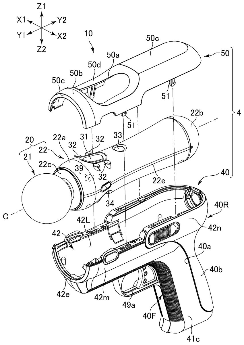
In the following, the controller assembly10will be described in detail. As shown inFIG. 2, the controller assembly10comprises the game controller20and the attachment4. The attachment4in this example includes an attachment main body40and a cover50attached to the attachment main body40.
FIG. 3is a perspective view of the controller assembly10.FIG. 4is a perspective view of the game controller20.FIG. 5is a perspective view of the attachment main body40.FIG. 6is a plan view of the attachment main body40.FIG. 7is a cross sectional view along the line VII-VII shown inFIG. 6.FIG. 8is a perspective view of the attachment main body40, and in this figure, an inside wall42L to be described later removed from the attachment main body40so that a structure for attaching the cover50to the attachment main body40are shown.FIG. 9is a perspective view of the cover50.
In the description below, the longitudinal direction of the game controller20is defined as the front-back direction (the Y1-Y2direction in the diagram (the Y1direction corresponds to a forward direction)); the direction orthogonal to the front-back direction, in which the grip41of the attachment main body40is elongated is defined as the up-down direction (the Z1-Z2direction in the diagram); and the direction orthogonal to both of the front-back and up-down directions is defined as the left-right direction (the X1-X2direction in the diagram).
Initially, the game controller20will be described. As shown inFIG. 2or4, the game controller20comprises a light emitting part21and a bar-shaped controller main body22. In this example, the controller main body22is formed in a substantial column shape. In detail, the controller main body22has a diameter that changes gradually in the longitudinal direction so as to be smaller in the middle part thereof in the longitudinal direction than in the front and rear parts. The foremost part22aof the controller main body22is shaped in a substantial frustum of circular cone, becoming thinner toward the front. That is, the diameter of the foremost part22abecomes gradually smaller toward the light emitting part21. Meanwhile, the rear end surface (an end surface opposite from the light emitting part21)22bof the controller main body22is formed substantially hemispherical.
A plurality of press buttons31to35are formed on the outer circumferential surface of the controller main body22so that a user can operate the buttons31to35while holding the controller main body22with his/her single hand. That is, a user can attach the game controller20to the attachment4and use those as the controller assembly10, and the user can use only the game controller20without the attachment4.
In this example, as shown inFIG. 2, the upper side in the front part of the controller main body22is provided with a first button31elongated in the front-back direction and a plurality of (four in this example) second buttons32positioned on the left and right sides of the first button32. Further, a power button33of the game controller20is provided at the rear of the first button31. Still further, side buttons34are provided on the left and right sides in the front part of the controller main body22. These side buttons34may function as, e.g., a start button to start a game and/or a select button to select a menu during a game.
As shown inFIG. 4or7, an analog button35is provided on the opposite side (a lower side in the front part of the controller main body22) from the first button31relative to the central line C along the longitudinal direction of the controller main body22. The game controller20sends, to the game device2, a signal indicating the press amount of the analog button35. The analog button35in this example is movable diagonally rearward toward the central line C around the fulcrum P formed inside the controller main body22, as indicated by the arrow D inFIG. 7, and a signal according to a press amount of the analogue button35is sent to the game device2.
As shown inFIG. 2or7, the controller main body22includes a built-in sensor39for detecting a movement and a posture of the game controller20. For example, the controller main body22includes, as the sensor39, one or more of an accelerator sensor for outputting a signal in accordance with acceleration applied to the game controller20, a geomagnetic sensor for outputting a signal in accordance with geomagnetism, and a gyro sensor for outputting a signal in accordance with an angular speed. As described above, an output signal from the sensor39is sent to the game device2, so that the game device2calculates a movement and a posture (orientation) of the game controller20, based on the output signal. In this example, the sensor39is mounted in the front part of the controller main body22.
As shown inFIG. 2or7, the light emitting part21is mounted on the front end surface22cof the controller main body22. That is, the light emitting part21is positioned further forward than the front end surface22cof the controller main body22. The light emitting part21in this example is formed substantially spherical with the center thereof positioned on the central line C of the controller main body22. The diameter R1of the light emitting part21is substantially equal to the diameter R2of the foremost part of the controller main body22(seeFIG. 7).
As shown inFIG. 7, the light emitting part21is hollow part and is made using light transmitting and light diffusing material (e.g., silicon resin). A light source23is held inside the front end of the controller main body22so as to emit light toward inside of the light emitting part21. The light from the light source23toward inside of the light emitting part21spreads radially through the outer surface of the light emitting part21. Three LED s (a light emitting diode) corresponding to, e.g., the optical three primary colors are provided as the light source23, and emit light with an intensity directed by the game device2. Therefore, the light emitting part21glows in various colors.
The light emitting part21has a part on the outer surface thereof, which is connected to the front end surface22cof the controller main body22. That is, as shown inFIG. 7, the light emitting part21has, between itself and the front end surface22cof the controller main body22, a coupling portion21acoupling the light emitting part21and the front end surface22c. The width W of the coupling portion21ain the direction orthogonal to the longitudinal direction (the front-back direction in this example) of the controller main body22is smaller than that of the light emitting part21(that is, the width W is smaller than the diameter R1of the light emitting part21), and thereby, light from the light emitting part21spreads partially diagonally rearward as well. This can ensure better recognition of the light emitting part21by the image capturing unit3.
In the following, the attachment4will be described. As shown inFIG. 2or3, the attachment main body40can be attached to the game controller20, and the cover50can be attached to the attachment main body40while covering the controller main body22.
The attachment main body40includes a grip41to be held by a user. Further, the attachment main body40includes an attached portion42formed along the controller main body22and attachable to, and detachable from, the controller main body22. As shown inFIG. 2or5, the attached portion42is formed elongated along the outer circumferential surface of the controller main body22toward the light emitting part21. Specifically, in this example, the attached portion42extends from the upper portion of the grip41toward the foremost part22aof the outer circumferential surface of the controller main body22. The attached portion42has a shape that can cover the lower side of the outer circumferential surface of the controller main body22and matches the outer shape of the controller main body22. In this example, as the controller main body22is formed in a substantial column shape, the inner surface of the attached portion42is formed in a shape of substantially halved a cylinder, of which cross section presents a substantially arc open upward. This structure allows the attached portion42and the controller main body22to be assembled together in the up-down direction (that is, the direction orthogonal to the longitudinal direction of the controller main body22). Further, since the middle part of the controller main body22is thinner than the front and rear parts thereof, as described above, the middle part of the inner surface of the attached portion42is resultantly positioned slightly higher than the front and rear parts thereof (seeFIG. 7). This makes the controller main body22hardly move forward relative to the attached portion42.
As shown inFIG. 5, the attached portion42has a rear wall42gpositioned at the rear of the controller main body22for covering the rear end surface22bof the controller main body22. In this example, as the rear end surface22bis formed substantially hemispherical, the inner surface of the rear wall42gis formed curved, forming a part of the hemisphere in accordance with the rear end surface22b.
A substantially round opening is formed open rearward on the rear wall42g, and a lid45is attached to the opening, as shown inFIGS. 5 and 7. Meanwhile, a connector (not shown) (e.g., a connector for an expansion device, such as a USB) is provided on the rear end surface22bof the controller main body22. With the lid45removed, a cable or the like can be connected to the connector of the controller main body22to charge the game controller20while the attachment main body40is kept attached to the controller main body22. In addition, the rear wall42ghas a long slit42iformed thereon and extending downward from an edge of the opening. Meanwhile, a hole22gis formed on the rear end surface22bof the controller main body22for threading a strap (not shown) or the like through (seeFIG. 4). A strap threaded in the opening22gcan be pulled outside of the rear wall42gvia the slit42i.
The attached portion42has a double structure. In detail, as shown inFIGS. 5,7, and8, the attached portion42has an inside wall42L and outside walls42m,42n. The inside wall42L is shaped curved to match the outer shape of the controller main body22, and forms the inner surface of the attached portion42. Meanwhile, the outside walls42m,42nforms the outer surface of the attached portion42. This arrangement can improve rigidity of the attached portion42while reducing the weight of the attachment main body40.
In this example, the outer surface of the attachment main body40is composed of three resin members each molded integral. Specifically, as shown inFIG. 3, the attachment main body40has a rear wall40R including the outside wall42nand a grip rear wall41b. The outside wall42nforms the outer surface in the rear part of the attached portion42. The grip rear wall41bextends downward from the outside wall42nto form the outer surface in the rear part of the grip41. In addition, the attachment main body40has left and right front walls40F defining the front part of the attachment main body40. Each front wall40F includes a grip front wall41cand an outside wall42m. The grip front wall41cforms an outer surface in the front part of the grip41. The outside wall42mextends forward from the upper part of the grip front wall41cto form the outer surface in the front part of the attached portion42. The left and right front walls40F and the rear wall40R are respectively formed integral using resin, and assembled together to thereby constitute the outer surface of the attachment main body40. Specifically, the left and right front walls40F are assembled together in the left-right direction using a screw61(seeFIG. 7), and the rear wall40R is assembled to the front walls40F such that the front edges40athereof match the rear edges of the front walls40F. As shown inFIG. 7or8, prongs40c,40fare formed on the rear edges of the front walls40F to be hooked on the edges40aof the rear wall40R.
The outside wall42mof the front wall40F is aligned to the outside wall42nof the rear wall40R in the front-back direction, both forming the outer surface of the attached portion42. The inside wall42L is placed inside the outside wall42mand the outside wall42n. In this example, as shown inFIG. 7, the inside wall42L has an annular fixing portion42zformed on the lower surface thereof and the fixing portion42zaccepts a boss into which a screw61is inserted. With the above, the inside wall42L is fixed to the outside walls42m,42n.
The attached portion42and the controller main body22of the game controller20A have a concave and a convex to be engaged with each other when the controller main body22is mounted on the attached portion4. In this example, a plurality of holes22d,22fare formed open downward on the outer circumferential surface of the controller main body22, as shown inFIG. 4. Specifically, the plurality of (two in this example) holes22dare formed on the left and right sides in the front part of the controller main body22, while the plurality of (two in this example) holes22fare formed on the left and right sides in the rear part of the controller main body22. Meanwhile, a plurality of (two in this example) projections (engagement portion)42aare formed projecting upward on the inner surface (the inside wall42L in this example) of the attached portion42, as shown inFIG. 5. Specifically, the projections42aare formed in the foremost part of the attached portion42, and their positions correspond to the holes22d. Therefore, when the controller main body22assembled to the attached portion42in the up-down direction, the projection42ais inserted into the hole22dto thereby regulate forward movement of the controller main body22and rotation of the same around the central line C. In this example, no such projection42ais formed in the rear part of the attached portion42. This makes it easier for a user to remove the controller20from the attached portion42by pulling up the front part (e.g., the light emitting part21) of the game controller20. However, the projection42amay be formed in the rear part of the attached portion42as well. Such an arrangement can ensure more stable mounting of the game controller20on the attached portion42.
The attached portion42additionally has fitting portions42bfor sandwiching the controller main body22from left and right sides of the controller main body22. In this example, as shown inFIG. 5, the fitting portions42bare formed as prongs on the left and right sides of the attached portion42, projecting inward of the attached portion42. Meanwhile, concaves22eare formed on the right and left sides of the outer circumferential surface of the controller main body22, as shown inFIG. 2. The concave22ein this example is a groove extending in the longitudinal direction of the controller main body22. When the controller main body22is mounted on the attached portion42, the left and right fitting portions42bare fit in the concaves22e, to thereby together sandwich the controller main body22. This makes it unlikely that the controller main body22is separated from the attached portion42in the up-down direction.
As shown inFIG. 5, the inner surface of the attached portion42, that is, the inside wall42L, has, on the left and right sides of the inside wall42L, plate-like moving portions42celongated along the outer circumferential surface of the controller main body22. Specifically, the moving portion42cextends upward from the lower edge thereof that is connected to the other part of the inside wall42L along the outer circumferential surface of the controller main body22. Accordingly, the left and right moving parts42ccan be slightly elastically deformed, widening outward in the left-right direction. The fitting portion42bis formed on the upper edge of the moving portion42c. When the controller main body22is being assembled into the attached portion42in the up-down direction, the fitting portion42bhits on the outer circumferential surface of the controller main body22, and thereby the left and right moving portions42care caused to widen outward.
As shown inFIG. 5, a plurality of cushions43a,43bare provided on the inner surface of the inside wall42L. The cushions43a,43bare made using, e.g., seat-shaped rubber or resin or damping material such as fiber. Specifically, the cushion43ais mounted on the bottom in the foremost part of the inside wall42L. The cushion43bis mounted on the bottom in the rearmost part of the inside wall42L. Further, left and right cushions43care mounted at the almost middle of the attached portion42in the longitudinal direction. This cushion43cas well is made using, e.g., seat-shaped rubber or resin or damping material such as fiber. The cushion43cis positioned in a lower part of the moving portion42c. When the controller main body22is mounted on the attached portion42, the outer circumferential surface of the controller main body22abut mainly on the cushions43a,43b,43c, but not on the other parts of the inner surface of the attached portion42.
The controller assembly10has the cover50, as described above. As shown inFIGS. 2 and 3, the cover50is arranged opposite the attached portion42in the up-down direction, and covers the upper side of the controller main body22. Similar to the attached portion42, the cover50is formed elongated along the outer circumferential surface of the controller main body22to the foremost part22aof the outer circumferential surface, covering the controller main body22. This configuration can prevent the game controller20from being separated from the attachment main body40. In this example, the attached portion42and the cover50are separately formed to be assembled together in the up-down direction. A structure for attaching the cover50to the attached portion42will be described later in detail.
Similar to the attached portion42, the cover50has a shape of substantially a halved cylinder. The cover50is placed on the attached portion42such that the respective left and right ends thereof are placed on respective those of the attached portion42so that the attached portion42and the cover50together constitute a cylindrical enclosure as a whole for accommodating the controller main body22. The attached portion42has the rear wall42gat the rear of the controller main body22that covers the rear end surface22b, as described above. Meanwhile, as shown inFIG. 9, the cover50has a rear wall50gthat covers, together with the rear wall42g, the rear end surface22bof the controller main body22. The rear end surface22bis formed substantially hemispherical, and the inner surface of the rear wall42gand the rear wall50gas well are both formed substantially spherical in accordance with the rear end surface22b. As a result, the attached portion42and the cover50together present a bottomed cylindrical shape as a whole.
As shown inFIG. 2or3, an opening50ais formed on the cover50, through which the buttons31to33arranged on the upper side of the controller main body22are exposed. Further, a lower wall50dis formed in an area surrounding the opening50a, the lower wall50dbeing concave relative to the foremost part50band rear part50cof the cover50. The lower wall50dis positioned lower in height than the buttons31to33, which makes it easier for a user to operate the buttons31to33.
The game controller20has the light emitting part21at the front end thereof, as described above. When the attachment main body40is attached to the game controller20, as shown inFIG. 3, the light emitting part21is positioned beyond the front end42eof the attached portion42in the longitudinal direction of the controller main body22. In other words, the attached portion42is formed such that the front end (that is, the front end of the attachment main body40) thereof is positioned more rearward than the light emitting part21. In this example, as shown inFIG. 7, the front end42eof the attached portion42is positioned more rearward than the coupling portion21apositioned between the light emitting part21and the front end surface22cof the controller main body22. This leaves the entire light emitting part21to be positioned more forward than the front end43eof the attached portion42.
Further, as shown inFIG. 3, when the cover50is attached to the attached portion42, the front end50eof the cover50is positioned more rearward than the light emitting part21. In other words, the light emitting part21is positioned outside the cylindrical enclosure constituted by the attached portion42and the cover50.
The front end42eof the attached portion42is formed in an arc shape surrounding the central line C of the game controller20. In this example, the front end50eof the cover50and the front end42eof the attached portion42together constitute an annular shape as a whole, not covering the front end surface22cof the controller main body22. That is, the front end surface22cof the controller main body22is exposed forward inside the front end50eof the cover50and the front end42eof the attached portion42. This structure can enlarge the space behind the light emitting part21, compared to a design with the front end surface22ccovered by the attached portion42and the cover50. And thus, the structure makes it less likely that progress of light from the light emitting part21is hindered by the attached portion42and the cover50.
As shown inFIG. 3, the outer circumferential surface of the foremost part50bof the cover50is formed inclined to extend forward and inward. In addition, the outer circumferential surface of the foremost part42fof the attached portion42as well is formed inclined to extend forward and inward. Accordingly, the outer circumferential surface of the cover50and that of the attached portion42together define, in the foremost parts50b,42f, a tapered shape that gradually becomes thinner toward the light emitting part (that is, forward). That is, the diameter of the cylinder constituted by the foremost parts50b,42fbecomes gradually smaller toward the light emitting part21. This makes it less likely that the foremost parts50b,42fhinder the light from the light emitting part21from proceeding. Further, the foremost part50bof the cover50is formed inclined to extend forward and inward. And, the foremost part42fof the attached portion42as well is formed inclined to extend forward and inward. According to this structure, the foremost part50band the foremost part42fcan surly prevents the forward movement of the controller main body22.
The attachment4includes the grip41to be held by a user, as described above. In this example, as shown inFIG. 2or3, the grip41extends downward from the rear part of the attached portion42so as to present, together with the attached portion42, a substantially L-shape. That is, when the attached portion42is attached to the controller main body22of the game controller20, the grip41extends in a bending direction relative to the longitudinal direction (the front-back direction in this description) of the controller main body22. In other words, the grip41extends in a direction of going farther away from the central line C of the controller main body22so that the grip41and the controller main body22are arranged to together present a substantially L-shape.
In this example, as shown inFIG. 7, the rear part of the controller main body22is positioned above the grip41. Moreover, since the attached portion42is formed swollen rearward beyond the upper part of the grip41, the controller main body22can be positioned more rearward than it would be with a design without such a swell. This achieves the center of gravity of the controller main body22defined in a position closer to the grip41. Such positioning can reduce a moment to be caused around the grip41when a user changes the orientation of the controller assembly10, which makes it easier for a user to move the controller assembly10.
The game controller20has the built-in sensor39arranged inside the controller main body22for detecting movement and posture of the game controller20, as described above. As shown inFIG. 7, when the attachment4attached to the game controller20, the sensor39is positioned more forward than the grip41, in detail, more forward than the front surface of the grip41. This makes it easier for the sensor39to detect a movement that changes the orientation of the controller assembly10.
In the following, a structure for attaching the cover50to the attachment main body40will be described. The cover50is attached to be placed on the attached portion42such that the left and right edges thereof are respectively placed on the left and right upper edges of the attached portion42. In detail, as shown inFIG. 9, a plurality of (two in this example) engagement portions51are formed on the left and right edges of the cover50, and a hook51ais formed on each engagement portion51. In this example, the engagement portion51is formed as a plate elongated downward from the respective left and right edge of the cover50, and the hook51ais formed on the outer surface of each engagement portion51. The two engagement portions51are positioned apart from each other in the front-back direction. Meanwhile, a plurality of engagement portions46aare formed on the left and right upper edges of the mount4to be hooked at the hooks51a, as shown inFIG. 8. When the hook51ais hooked at the engagement portion46a, the cover50is fixed to the attached portion42. Moreover, the attached portion42has sliders46on the respective left and right sides thereof. The plurality of (two in this example) engagement portions46aare formed on each slider46. In this regard, the slider46is a plate-like member and disposed between the inside wall42L and the outside walls42m,42n, which constitute the double structure of the attached portion42described above.
Each slider46is slidable in the direction along the left and right upper edges of the attached portion42(that is, the front-back direction). Specifically, the slider46can slide rearward from the position where the engagement portion46ahits on the hook51a(hereinafter referred to as an engaged position (the position of the slider46shown inFIG. 8)). Therefore, when the hook51aof the engagement portion51hits on the engagement portion46a, the slider46resultantly moves rearward from the engaged position. As shown inFIG. 8, a spring47is provided at the rear of the slider46for urging the slider46toward the engaged position. This makes the slider46to be pushed back toward the engaged position by the spring47after the hook51ahas gone downward beyond the engagement portion46a. This causes the hook51ato be hooked at the engagement portion46a. In this regard, the slider46is guided for movement by the inner surfaces of the outside walls42m,42n.
As shown inFIG. 5, edge plates42q,42rare provided on the respective left and right upper edges of the attached portion42. The edge plates42q,42rare formed as substantially horizontal plates, and placed perpendicular to the direction in which the cover50is attached (the up-down direction). Holes are formed open upward on the edge plate42q,42r. In the engaged position, the engagement portions46aare positioned below the holes formed on the edge plates42q,42r. The engagement portion46amoves rearward from the position of the hole as the slider46moves.
In this regard, the edge plates42q,42rare formed integral with the respective outside walls42m,42n. The rear edge plate42rformed integral with the outside wall42nis positioned higher than the front edge plate42qformed integral with the outside wall42m. Further, an additional hole42yis formed on the edge plate42r. As shown inFIG. 9, a convex52is formed on the respective left/right edge of the cover50to be inserted in the hole42yto thereby regulate the position of the cover50relative to the attached portion42.
A part of the slider46is exposed outside in the left-right direction through an opening42pformed on the outside wall42n. In detail, an operating portion46belongated in the front-back direction is formed on the slider46to swell slightly outward in the left-right direction in a position inside the opening42p. The opening42pis longer than the operating portion46bin the front-back direction to allow the above described front-back movement of the slider46. A user can move the operating portions46bof the left and right sliders46rearward while holding the operating portions46b, to thereby release engagement between the engagement portion46aand the hook51ato remove the cover50from the attached portion42.
In this regard, the operating portion46bis positioned between the two engagement portions46aprovided apart from each other in the front-back direction. In detail, as shown inFIG. 8, the slider46has a rod46cextending forward from the operating portion46band positioned below the edge plate41g, and the front engagement portion46ais positioned on the side of the front end of the rod46c. The rear engagement portion46ais positioned more rearward than the operating portion46b.
As shown inFIG. 7, the attachment main body40has an operating member49provided below the inside wall42L. The operating member49has a trigger49aformed in a rear part thereof, in particular, in a position in front of the upper part of the grip41. Further, an opening is formed on the front surface of the grip41so that the rear part of the trigger49ais inserted into the opening. The operating member49is movable in the front-back direction, so that a user can pull the trigger49abackward. A spring48is provided above the operating member49so that the operating member49is urged forward by the spring48.
As shown inFIG. 7, the controller main body22is placed such that the analog button35faces the bottom of the attached portion42in the up-down direction. When the controller main body22is mounted on the attached portion42, the analog button35, formed in the front part of the controller main body22, is resultantly positioned apart forward from the trigger49a. The trigger49ais provided with an arm49bextending forward from the trigger49a, and movement of the trigger49ais transmitted to the analog button35through the arm49b. In detail, the arm49bextends forward from the upper part of the trigger49aand has a wall-shaped projection49con the front end thereof. The projection49cprojects upward through a hole42uformed on the inside wall42L (seeFIG. 5) to be positioned in front of the analog button35. Therefore, when the trigger49amoves rearward, the rear surface (hereinafter referred to an abutment surface)49dof the projection49chits on, and thereby presses, the analog button35.
As shown inFIG. 7, the tip end of the analog button35projects downward beyond the outer circumferential surface of the controller main body22(that is, projects toward outside of the controller main body22in the radial direction), thus being inserted in the hole42uand abutting on a lower part of the abutment surface49d. The analog button35is adapted to diagonally rearward and upward movement around the fulcrum P, as described above. Therefore, when the analog button35is pressed by the abutment surface49dand thereby moves diagonally rearward and upward, the tip end of the analog button35moves up while sliding on the abutment surface49d.
Further, since the analog button35moves diagonally rearward and upward around the fulcrum P, the movement amount of the analog button35in diagonally upward direction relative to the movement amount of the operating member49in rearward direction is changing to be gradually larger. In this example, since the abutment surface49dis formed curved so that such a change in the movement amount of the analog button35relative to that of the operating member49become reduced. Specifically, the abutment surface49dis curved such that the distance from the analog button35to the abutment surface49dbecome larger toward the above. That is, the abutment surface49dis formed inclined forward and curved while swelling diagonally rearward and upward.
The front surface of the analog button35is formed inclined so as to extend diagonally upward and forward. Meanwhile, the abutment surface49dis formed inclined forward, as described above. Therefore, the analog button35buts on the abutment surface49donly on the tip end thereof but not on other parts thereof as the analog button35moves.
The side buttons34are provided on the respective left and right sides on the outer circumferential surface of the game controller20, as described above. Moreover, the respective left and right upper edges of the attached portion42has through-holes formed thereon which penetrates the attached portion42in the left-right direction. An operating member62is arranged inside the through-hole and movable in the left-right directions relative to the attached portion42. The position of the operating member62corresponds to the position of the side button34, so that a user can operate the side button34by pressing the operating member62.
As described above, the controller assembly10comprises a game controller20and an attachment4. The game controller20has a bar-shaped controller main body22and a light emitting part21provided at the front end22cof the controller main body22. The attachment4has the attached portion42formed along the outer circumferential surface of the controller main body22and attachable to, and detachable from, the controller main body22. Further, the attachment4includes a grip41for being held by a user. The attached portion42is formed such that the front end42ethereof is positioned more rearward than the light emitting part21when the attached portion42is attached to the game controller20. This structure can prevent deterioration in recognition of the light emitting part21by the image capturing unit3.
The grip41is formed to extend in a bending direction relative to the longitudinal direction of the game controller20when the attached portion42is attached to the game controller20. According to this arrangement, the controller assembly10can have a gun shape. Further, this structure makes it possible for a user to readily direct the light emitting part21forward while holding the grip41.
The attached portion42is formed to extend forward along the outer circumferential surface of the game controller20when the attached portion42is attached to the game controller20. This structure ensures stable attachment of the attached portion42to the game controller20.
The light emitting part21of the game controller20is formed substantially spherical, and the front end42eof the attached portion42is formed in an arc shape that surrounds the central line of the game controller20. This structure makes it unlikely that the light from the light emitting part21is blocked by the attached portion42.
The attachment4has a cover50arranged opposite the attached portion42and covering the game controller20. The attached portion42and the cover50are formed to together have a cylindrical shape capable of accommodating the game controller20. This structure ensures stable holding of the game controller20by the attached portion42and the cover50. Alternately, the cover50may be formed either integral with or separately from the attached portion42.
The foremost part50bof the cover50and the foremost part42fof the attached portion42are formed to have a cylindrical shape becoming thinner toward the front. This structure makes it unlikely that the light from the light emitting part21toward diagonally rearward is blocked by the attached portion42and the cover50.
The cover50is formed separately from the attached portion42and so as to be attachable to, and detachable from, the attached portion. This structure makes it easier to attach the attached portion42to the game controller20compared to a design in which the cover50and the attached portion42are formed integral with each other to together have a cylindrical shape so that the game controller20is inserted into the cylinder from either the front or rear side thereof. In addition, when the light emitting part21is designed larger, the attached portion42can be attached to the game controller20.
The game controller20includes a bar-shaped controller main body22, and a coupling portion21apositioned between and coupling the controller main body22and the light emitting part21. The attached portion42is formed such that the front end42eof the attached portion42is positioned more rearward than the coupling portion21awhen the attached portion42is attached to the controller main body22. With this structure, the entire light emitting part21is positioned more forward than the front end42eof the attached portion42, which further improves recognition of the light emitting part21by the image capturing unit3.
The game controller20includes a bar-shaped main body22. The cover50and the attached portion42are formed so as to extend along the outer circumferential surface of the controller main body22to the foremost part22aof the outer circumferential surface. This structure enables stable holding of the controller main body22by the attached portion42and the cover50.
The attached portion42has a projection42aformed thereon to be inserted in the concave22dformed on the outer circumferential surface of the game controller20. This structure can regulate relative movement of the game controller20relative to the attachment4.
The game controller20incorporates a built-in sensor39for detecting movement of the game controller20. The grip41is positioned more rearward than the sensor39when the attached portion42is attached to the controller main body22. This structure facilitates detection of movement that changes the orientation of the game controller assembly10.
Note that the present invention is not limited to the above described controller assembly10, and can be modified in various manners.
For example, although the cover50and the attached portion42are separately formed in the above description, the cover50and the attached portion42may be formed integral with each other so as to together constitute a cylindrical shape as a whole. In this case, the controller main body22is inserted into the cylindrical enclosure from the front side thereof.
Further, although the rear part of the controller main body22is positioned above the grip41in the above description, the controller main body22may be positioned apart forward from the grip41.
Further, although the controller main body22is formed in a substantial column shape, and the attached portion42and the cover50are formed to have a substantial cylindrical shape as a whole in the above description, the controller main body22may be formed in a substantially rectangular solid shape, and the attached portion42and the cover50may be formed in a rectangular barrel shape as a whole.
Further, although the controller assembly10has the cover50attached thereto, the controller assembly10may not have the cover50.
Claims
- An attachment for a game controller, the game controller including: (i) a bar-shaped controller main body having an outer circumferential surface of varying diameter along a longitudinal direction thereof, where the diameter gradually reduces to a first diameter at a foremost part at a front end surface of the controller main body;(ii) a coupling portion located on the front end surface of the controller main body and having a second diameter that is smaller than the first diameter, and (iii) a light emitting part coupled to the front end surface via the coupling portion and being substantially in the form of a sphere having a third diameter larger than the second diameter, the attachment comprising: a grip for being held by a user;and an attached portion attachable to, and detachable from, the outer circumferential surface of the controller main body, the attached portion including a front end at a most forward portion thereof, and an inner surface having a contour in complimentary conformity with the outer circumferential surface of the controller main body such that a fourth diameter of the inner surface also reduces substantially to the first diameter of the foremost part at the front end surface of the controller main body, wherein the attached portion is formed such that the front end surface of the controller main body is exposed and positioned forward of the front end of the attached portion, and the front end of the attached portion is positioned more rearward than the coupling part and the light emitting part when the attached portion is attached to the controller main body.
- The attachment according to claim 1 , wherein the grip is formed to extend in a bending direction relative to the longitudinal direction of the controller main body when the attached portion is attached to the controller main body.
- The attachment according to claim 2 , wherein: the outer circumferential surface of the controller main body includes a middle portion having a diameter smaller than both the first diameter at the foremost part and a diameter at an opposing rearmost part of the controller main body;the inner surface of the attached portion includes a middle portion having a contour in complimentary conformity with the middle portion of the outer circumferential surface of the controller main body, such that the middle portion of the inner surface swells inwardly to substantially meet the diameter of the middle portion of the controller main body;and the attachment portion includes an operating member located below the inner surface thereof, the operating member being biased forward by a spring.
- The attachment according to claim 1 , wherein the attached portion is formed to extend forward along the outer circumferential surface of the game controller when the attached portion is attached to the controller main body.
- The attachment according to claim 4 , wherein the light emitting part of the game controller is substantially spherical, and the front end of the attached portion is formed in an arc shape that surrounds a central line along the longitudinal direction of the controller main body.
- The attachment according to claim 4 , further comprising: a cover arranged opposite the attached portion, for covering the controller main body, wherein the attached portion and the cover are formed to have a cylindrical shape capable of accommodating the controller main body.
- The attachment according to claim 6 , wherein a front part of the cover and a front part of the attached portion are formed to have a cylindrical shape having a decreasing diameter toward the front.
- The attachment according to claim 6 , wherein the cover is formed separately from the attached portion so as to be attachable to, and detachable from, the attached portion.
- The attachment according to claim 6 , wherein: the outer circumferential surface of the controller main body includes a middle portion having a diameter smaller than both the first diameter at the foremost part and a diameter at an opposing rearmost part of the controller main body;the inner surface of the attached portion includes a middle portion having a contour in complimentary conformity with the middle portion of the outer circumferential surface of the controller main body, such that the middle portion of the inner surface swells inwardly to substantially meet the diameter of the middle portion of the controller main body;and the attachment portion includes sliders disposed at the middle portion thereof, each slider having an engagement portion for securing the cover to the attached portion.
- The attachment according to claim 1 , wherein the attached portion has a projection formed thereon to be inserted in a concavity formed on the outer circumferential surface of the controller main body.
- The attachment according to claim 1 , wherein: the game controller incorporates a built-in sensor for detecting movement of the game controller, and the grip is formed to be positioned more rearward than the sensor when the attached portion is attached to the controller main body.
- A controller assembly, comprising: a game controller, the game controller including: (i) a bar-shaped controller main body having an outer circumferential surface of varying diameter along a longitudinal direction thereof, where the diameter gradually reduces to a first diameter at a foremost part at a front end surface of the controller main body;(ii) a coupling portion located on the front end surface of the controller main body and having a second diameter that is smaller than the first diameter, and (iii) a light emitting part coupled to the front end surface via the coupling portion and being substantially in the form of a sphere having a third diameter larger than the second diameter;and an attachment for the game controller, wherein the attachment includes: a grip for being held by a user, and an attached portion attachable to, and detachable from, the outer circumferential surface of the controller main body, the attached portion including a front end at a most forward portion thereof, and an inner surface having a contour in complimentary conformity with the outer circumferential surface of the controller main body such that a fourth diameter of the inner surface also reduces substantially to the first diameter of the foremost part at the front end surface of the controller main body, wherein the attached portion is formed such that the front end surface of the controller main body is exposed and positioned forward of the front end of the attached portion, and the front end of the attached portion is positioned more rearward than the coupling part and the light emitting part when the attached portion is attached to the controller main body.
Disclaimer: Data collected from the USPTO and may be malformed, incomplete, and/or otherwise inaccurate.