U.S. Pat. No. 8,298,080
VIRTUAL SPACE DISPLAY DEVICE, VIEWPOINT SETTING METHOD, AND INFORMATION RECORDING MEDIUM
AssigneeKonami Digital Entertainment Co Ltd
Issue DateAugust 13, 2010
Illustrative Figure
Abstract
A setting unit sets a position of a viewpoint arranged in a virtual space, and a direction of a visual line extending from the viewpoint. A moving unit moves a player character in the virtual space according to an operation by a player. A generating unit generates an image representing the way the virtual space is viewed from the viewpoint toward the direction of the visual line. A display unit displays the generated image on a screen. Moreover, the setting unit sets a position of the viewpoint so that a relative position of the viewpoint to an object is fixed, sets a position of a target point included in a surface of a predetermined shape fixed relatively to the object at random, and sets a direction of the visual line so that an intersection point between the surface and the visual line gradually comes closer to the target point.
Description
DETAILED DESCRIPTION An explanation will be given of an embodiment of the present application. In order to facilitate understanding below, the explanation will be given of the embodiment in which the present application is applied to a gaming device, but the present application can be applied to various information processing devices, such as various computers, PDAs, and cellular phones in the same manner as the embodiment. That is, the following embodiment to be explained below is merely for explanation, and is not to limit the scope of the present application. Consequently, those skilled in the art can adopt embodiments in which some of or all of the structural elements are replaced with respective equivalents, and it should be understood that such embodiments are to be included within the scope of the present application. First Embodiment FIG. 1is a block diagram showing a schematic configuration of a typical gaming device which realizes a virtual space display device according to an embodiment of the present application. An explanation will be given with reference toFIG. 1. A gaming device100comprises a CPU (Central Processing Unit)101, a ROM (Read Only Memory)102, a RAM (Random Access Memory)103, an interface104, a controller105, an external memory106, a DVD (Digital Versatile Disc)-ROM drive107, an image processing unit108, a sound processing unit109, and an NIC (Network Interface Card)110. First, a player loads a DVD-ROM which stores a program and data for games in the DVD-ROM drive107. Next, the player turns on the gaming device100. This allows the program to be run, and the virtual space display device of the embodiment is realized. The CPU101controls the overall operation of the gaming device100. The CPU101is connected to each structural element, and exchanges control signals and data. Note that the CPU101has an interval timer, and can clock a time in accordance with a ...
DETAILED DESCRIPTION
An explanation will be given of an embodiment of the present application. In order to facilitate understanding below, the explanation will be given of the embodiment in which the present application is applied to a gaming device, but the present application can be applied to various information processing devices, such as various computers, PDAs, and cellular phones in the same manner as the embodiment. That is, the following embodiment to be explained below is merely for explanation, and is not to limit the scope of the present application. Consequently, those skilled in the art can adopt embodiments in which some of or all of the structural elements are replaced with respective equivalents, and it should be understood that such embodiments are to be included within the scope of the present application.
First Embodiment
FIG. 1is a block diagram showing a schematic configuration of a typical gaming device which realizes a virtual space display device according to an embodiment of the present application. An explanation will be given with reference toFIG. 1.
A gaming device100comprises a CPU (Central Processing Unit)101, a ROM (Read Only Memory)102, a RAM (Random Access Memory)103, an interface104, a controller105, an external memory106, a DVD (Digital Versatile Disc)-ROM drive107, an image processing unit108, a sound processing unit109, and an NIC (Network Interface Card)110.
First, a player loads a DVD-ROM which stores a program and data for games in the DVD-ROM drive107. Next, the player turns on the gaming device100. This allows the program to be run, and the virtual space display device of the embodiment is realized.
The CPU101controls the overall operation of the gaming device100. The CPU101is connected to each structural element, and exchanges control signals and data. Note that the CPU101has an interval timer, and can clock a time in accordance with a set timer value.
An IPL (Initial Program Loader) which is executed immediately after the power is turned on is recorded in the ROM102. When the IPL is executed, the program recorded in the DVD-ROM is read out in the RAM103, thereby causing the CPU101to run the program. Moreover, the ROM102records a program and various data for an operating system. The operating system is necessary to control the overall operation of the gaming device100.
The RAM103temporarily stores data and programs. The RAM103retains the program and data which are read out from the DVD-ROM, and other data necessary for the progress of a game and a chat communication.
The controller105which is connected through the interface104in an operable manner receives an operation input performed when a user plays a game. For example, the controller105receives an input of letter strings (messages) or the like in accordance with an operation input. In addition, the controller105receives, for example, an input of a movement instruction or the like to an operation-target character.
The external memory106is detachably connected through the interface104. The external memory106stores data which represents a progress status of the game, and data like the log (a record) of a chat communication. The external memory106is rewritable. When the player inputs an instruction through the controller105, these pieces of data may be appropriately recorded in the external memory106.
The DVD-ROM is loaded in the DVD-ROM drive107. The DVD-ROM may be utilized to record programs for realizing the game, and image data and sound data accompanying the game. Under the control of the CPU101, the DVD-ROM drive107performs a read-out process on the DVD-ROM loaded therein. The DVD-ROM drive107reads out a necessary program and data. The read-out program and data are temporarily stored in the RAM103or the like.
The image processing unit108preferably cause an image computation processor (not illustrated) possessed by the CPU101and the image processing unit108to process data read from a DVD-ROM. Thereafter, the image processing unit108preferably records image information in a frame memory (not illustrated). The image information recorded in the frame memory is preferably converted into a video signal (an image signal) at a predetermined synchronization timing. The video signal (the image signal) is preferably output to a monitor connected to the image processing unit108. This enables display of various images.
Note that the image computation processor can perform an overlay operation of two-dimensional images, a transparency operation like a blending, and various saturation operations at a high speed.
Moreover, the image computation processor can perform an operation of acquiring a rendered image at a high speed. The rendered image can be acquired by rendering polygon information through Z-buffering, and by looking down a polygon from a predetermined view position. The polygon is arranged in a virtual three-dimensional space. Moreover, various texture information is added to the polygon information.
Furthermore, as the CPU101and the image computation processor work together, it becomes possible to depict letter strings as a two-dimensional image in the frame memory, or on each polygon surface. The letter string is depicted in accordance with font information which defines the shape of a letter. The font information is recorded in the ROM102. However, exclusive font information recorded in the DVD-ROM may be used.
The sound processing unit109preferably converts sound data which is read out from the DVD-ROM into an analog sound signal. Next, the sound processing unit109preferably supplies the sound signal to an external speaker and outputs sound. For example, the sound processing unit109preferably generates sound effects and music data to be generated during the progress of the game under the control of the CPU101. The sound processing unit109preferably causes the speaker to output sound corresponding to the generated sound effect or the like.
The NIC110is preferably used when the gaming device100is connected to a computer communication network (not illustrated) like the Internet. The NIC110is an interface which intermediates various Internet-connecting devices (not illustrated) and the CPU101. Such various Internet-connecting devices may be a 10BASE-T/100BASE-T compatible product which is used for establishing a LAN (Local Area Network), an analog modem, an ISDN (Integrated Services Digital Network) modem, and an ADSL (Asymmetric Digital Subscriber Line) modem which are for connecting to the Internet via a telephone line, and a cable modem for connecting to the Internet via a cable television line and the like.
Moreover, the gaming device100may have a large-capacity external memory device like a hard disk drive which functions as the ROM102, the RAM103, the external memory106, and the DVD-ROM loaded in the DVD-ROM drive107and the like.
Furthermore, a configuration that a keyboard and a mouse are connected may be employed. The keyboard receives an editing input of letter strings from a user. Moreover, the mouse receives inputs of specifying and selecting various positions.
Furthermore, instead of the gaming device100of the embodiment, an ordinary computer (e.g., a general-purpose personal computer) can be used as the virtual space display device. For example, the ordinary computer comprises, like the gaming device100, a CPU, a RAM, a ROM, a DVD-ROM drive, and an NIC. The ordinary computer further comprises an image processing unit which has a simpler function than that of the gaming device100. Moreover, the ordinary computer may have a hard disk drive as an external memory device, and can use a flexible disk, a magneto-optical disk, a magnetic tape and the like. Furthermore, in the ordinary computer, a keyboard and a mouse are used as an input device instead of a controller. When a program for games is installed and is run, the ordinary computer functions as the virtual space display device.
General Configuration of the Virtual Space Display Device>
FIG. 2is a block diagram for explaining a general configuration of structural elements of the virtual space display device, assuming that a virtual space display device200executes an action game which freely moves a player character in a virtual space (e.g., a game field) in accordance with an operation by a player. An explanation will be given with reference to theFIG. 2.
The virtual space display device200comprises a moving unit730, a setting unit740, a generating unit750, and a display unit260.
The moving unit730preferably moves an object in the virtual space.
The setting unit740preferably sets a position of a viewpoint arranged in the virtual space, and a direction of a visual line extending from the viewpoint.
The generating unit750preferably generates an image representing the way the virtual space where the object moves is viewed from the set viewpoint into the set direction of the visual line.
The display unit260preferably displays the generated image on a screen.
Note that the setting unit740sets the position of the viewpoint in such a way that a relative position of the viewpoint to the object is fixed.
The setting unit740randomly preferably sets a position of a target point included in a plane of a predetermined shape which is relatively fixed to the object.
Moreover, the setting unit740preferably sets a direction of the visual line in such a way that an intersection point between the plane and the visual line gradually comes close to the target point.
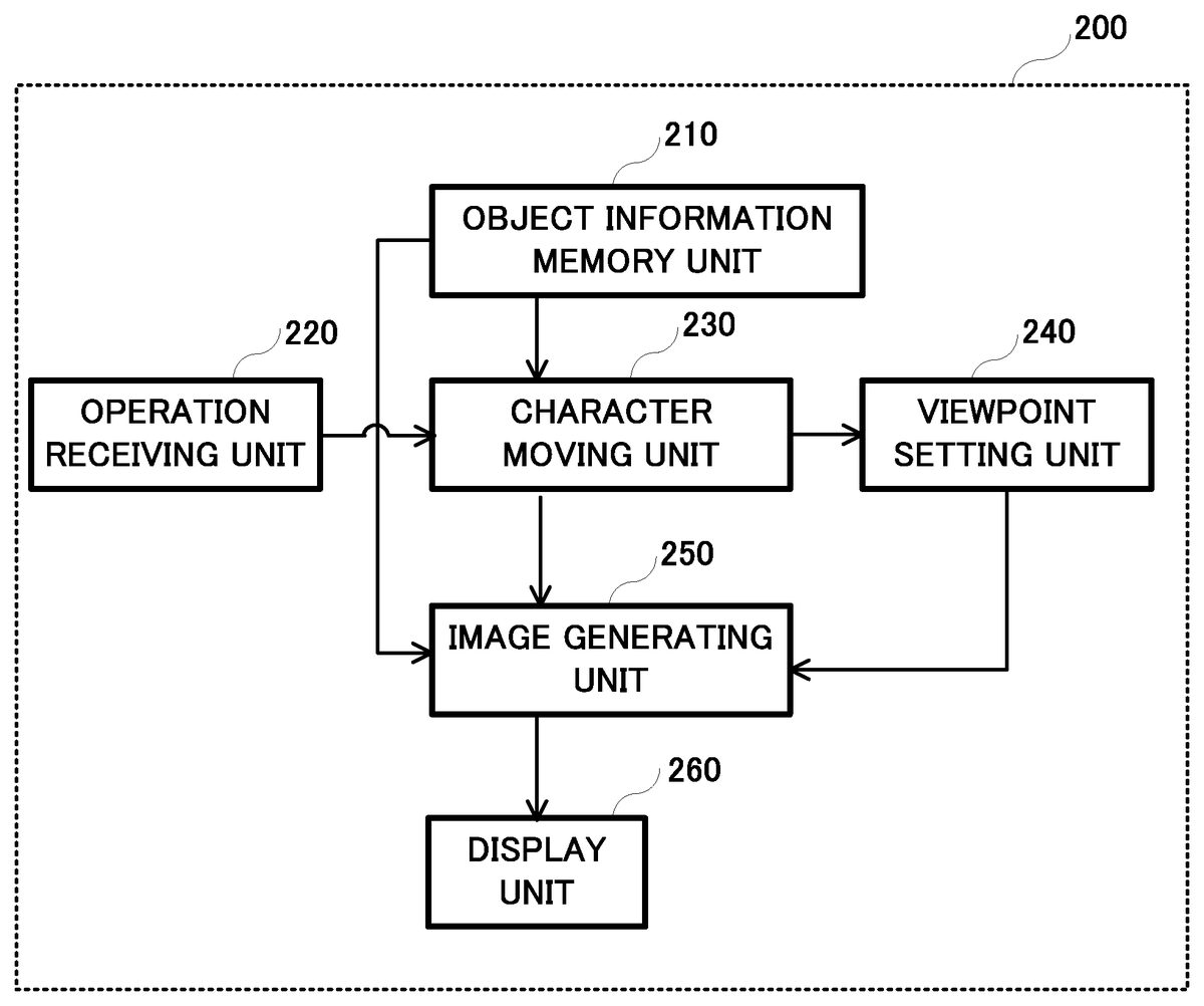
FIG. 3is a block diagram showing the schematic configuration of the virtual space display device200further in detail. An explanation will be given with reference to this diagram.
The virtual space display device200preferably comprises an object information memory unit210, an operation receiving unit220, a character moving unit230, a viewpoint setting unit240, an image generating unit250, and a display unit260. Moreover, although functions of individual units are correlated with one another, it is possible to appropriately change employment/non-employment of individual units depending on purposes.
First, the object information memory unit210preferably stores information on various objects, such as a player character (e.g., a main character), an enemy character, a tree, a rock, and a building. Each object is preferably arranged in a virtual space. More specifically, information on each object, such as a three-dimensional model and a texture, is preferably stored.
Note that the DVD-ROM which is loaded in the DVD-ROM drive107, the RAM103and the like can function as the object information memory unit210.
The operation receiving unit220preferably receives an operation input like an action instruction or the like to a player character operated by a player. For example, any one of a plurality of buttons (e.g., a direction key, an A button, a B button, an X button, and a Y button arranged on the controller105) which may correspond to respective actions, such as, for example, moving in a predetermined direction, using a sword or a weapon (shooting a gun or wield a sword), picking up an item, squatting down, and lying down may be pressed by the player, and this action is regarded as performed by an operation input. Note that movement instructions to the player character may include an instruction of walking, running, or the like as an example.
Note that the controller105can function as the operation receiving unit220.
The character moving unit230preferably corresponds to the moving unit730as explained above.
The character moving unit230accordingly preferably moves a character in a virtual space. For example, the character moving unit230may manage positional information (e.g., a current position and a direction) on a player character, an enemy character or the like in the virtual space, and moves a character by changing a current position and a direction of the character.
More specifically, the character moving unit230may move the player character in the virtual space in accordance with a movement instruction or the like received by the operation receiving unit220. Moreover, the enemy character in the virtual space is preferably moved in accordance with a predetermined logic or the like.
Note that the RAM103and the CPU101can function as the character moving unit230.
The viewpoint setting unit240preferably corresponds to the setting unit740as explained above.
For example, in a case of a third-person viewpoint mode (a looking-down viewpoint), the viewpoint setting unit240preferably sets a position of a virtual camera (a view point position) obliquely upward and behind (back) a player character. The viewpoint setting unit240sets a direction of a visual line so that the player character is looked down from the position of the virtual camera.
As an example, as shown inFIG. 4A, the viewpoint setting unit240preferably sets a position of a virtual camera VC at a position separated by a fixed distance L at an angle θ with reference to a horizontal surface HO behind the player character PC. Note that the viewpoint setting unit240preferably sets the position of the virtual camera VC so as to follow the movement of the player character PC when the player character PC moves in the virtual space. That is, a position of a viewpoint is preferably set so that a relative position of the viewpoint to the player character PC is fixed. When there is an obstacle or the like between the player character PC and the virtual camera VC, the position of the virtual camera VC is preferably appropriately set so as to avoid the obstacle or the like.
Moreover, the viewpoint setting unit240preferably sets a target point MP on a flat surface HM having, for example, a predetermined size as shown inFIG. 4B, assuming that the flat surface HM is defined with reference to a waist part of the player character PC. The viewpoint setting unit240preferably sets a direction of a visual line of the virtual camera VC toward the target point MP. A reference position (an initial position) of the target point MP is preferably defined, for example, at the center of the flat surface HM. When the player character PC is not moving, the target point MP is preferably set at the reference position (i.e., the center) of the flat surface HM. Conversely, when the player character PC is moving, the target point MP is preferably set in the flat surface HM at random. Note that, inFIG. 4B, although the flat surface HM is preferably formed in a rectangle, a shape of the flat surface HM and a size of thereof are merely examples, and the shape of such flat surface may be a circular shape or the like other than the rectangle. Moreover, although a planar surface is used as the flat surface HM to facilitate understanding, a shape of the surface may be a curved surface or the like other than the planar surface.
An explanation will be given of setting of a position of the target point MP in detail. The viewpoint setting unit240preferably generates a random number at a time interval corresponding to a speed at which the player character PC moves. The viewpoint setting unit240sets the target point MP at a position shifted from a center on the flat surface HM according to the random number.
In more detail, while the player character PC is running, for example, the viewpoint setting unit240generates a one-dimensional random number having a time associated with running (a speed) as an expected value. More specifically, the viewpoint setting unit240preferably acquires a timer value (an interval timer value) T by multiplying a reference time (a base value corresponding to a speed) by a random value. As a specific example, the viewpoint setting unit240preferably acquires the timer value T through an operation of an equation 1 below. Because the viewpoint setting unit240acquires the timer value T by multiplying a sum of two random values each within a value of 1 by a base value, the timer value T becomes zero time to twice as much as the base value.
T=Tb×(Ra+Rb) [Equation 1]where:T: a timer valueTb: a base value (a time to be a base corresponding to a speed)Ra, Rb: random values (each within a value of 1)
Note that the equation 1 is an example for specifically explaining how to calculate the timer value T. Accordingly, calculation method of the timer value T is not limited to this equation. The viewpoint setting unit240may calculate the timer value T through other equations.
The viewpoint setting unit240preferably generates a two-dimensional random number having a center position of the flat surface HM as an expected value after a time having the acquired timer value T has elapsed. More specifically, as shown inFIG. 4C, the viewpoint setting unit240preferably acquires a shifted angle α at random with reference to a center P, and further acquires a shifted amount (an amount to be shifted) D at random. More specifically, the viewpoint setting unit240preferably acquires the shifted amount D by multiplying a reference shifted amount (a base shifted amount) by a random value or the like. As a specific example, the viewpoint setting unit240preferably acquires the shifted amount D through an operation of equation 2 below.
D=Db×(R+0.2) [Equation 2]where:D: a shifted amountDb: a base shifted amount (an amount to be a base)R: a random value (within a value of 1)0.2: a value to avoid being 0 (the value is not limited to 0.2, and can be appropriately changed)
Note that the equation 2 is an example for specifically explaining how to calculate the shifted amount D. Accordingly, the calculation method of the shifted amount D is not limited to this equation. The viewpoint setting unit240may calculate the shifted amount D through other equations. In this manner, the viewpoint setting unit240preferably sets the target point MP at a position shifted from the center P by the shifted amount D on a line of the shifted angle α.
The viewpoint setting unit240preferably sets a direction of a visual line of the virtual camera VC so that the virtual camera is directed to the set target point MP. At this time, if the viewpoint setting unit240directly sets a direction of the visual line toward the target point MP, an image is jiggled too hard. Consequently, the viewpoint setting unit240sets a direction of the visual line so that the visual line asymptotically approaches the target point MP for multiple times. For example, as shown inFIG. 4D, the viewpoint setting unit240sets a direction of the visual line so that the visual line asymptotically approaches the target point MP for multiple times. At this time, the viewpoint setting unit240changes the asymptotic value (an amount to be asymptotically approached) until the visual line penetrates the target point MP within a range of, for example, plus or minus 25%.
Accordingly, the viewpoint setting unit240preferably sets the target point MP at a position irregularly shifted from the center P of the flat surface HM at a time (a base value multiplied by a random value) interval corresponding to the speed of the player character PC. The viewpoint setting unit240sets a direction of the visual line so that the visual line asymptotically approaches the target point MP for multiple times.
More specifically, an explanation will be given of a case in which, with the target point MP being at the center P, a timer value Ta is calculated and an A point is calculated as a target point at a time t1, and then a timer value Tb is calculated at a time t2as shown inFIG. 5A.
First, as shown inFIG. 5B, the viewpoint setting unit240has set a visual line e1at the center P at the time t1. While a time having the calculated timer value Ta elapses, i.e., from the time t1to the time t2, the viewpoint setting unit240preferably sequentially sets visual lines e2, e3, e4, and e5in this order toward the calculated A point. That is, the viewpoint setting unit240preferably asymptotically sets a direction of the visual line from the center P to the A point.
Next, as shown inFIG. 5C, the viewpoint setting unit240has set the visual line e5at the A point at the time t2. While a time having the calculated timer value Tb elapses, i.e., from the time t2to a time t3, the viewpoint setting unit240preferably sequentially sets visual lines e6, e7, and e8in this order toward a calculated B point. That is, the viewpoint setting unit240asymptotically sets a direction of the visual line from the A point to the B point.
The viewpoint setting unit240preferably repeats the same process after time t3if the player character PC is moving.
The CPU101can function as the viewpoint setting unit240.
Returning now toFIG. 3, the image generating unit250preferably corresponds to the generating unit750. The image generating unit250preferably generates a game image which represents the interior of a virtual space as viewed from a viewpoint toward a direction of a visual line. The image is preferably generated in accordance with information on an object stored in the object information memory unit210, positional information on a character managed by the character moving unit230, and a position of a virtual camera and a direction of a visual line both set by the viewpoint setting unit240.
For example, as shown inFIG. 6A, the image generating unit250preferably generates a game image that allows a player to feel hand jiggling of the virtual camera.
More specifically, an explanation will be given of a case in which the viewpoint setting unit240sets a direction of a visual line as shown inFIG. 5AtoFIG. 5C. As shown inFIG. 6C, the image generating unit250preferably generates a jiggled game image that faces toward the direction of the arrows from the time t1to the time t2(while the timer value Ta elapses) inFIG. 6B. Moreover, as shown inFIG. 6D, the image generating unit250preferably generates a jiggled game image that moves toward the direction of the arrows from the time t2to the time t3(while the timer value Tb elapses) inFIG. 6B.
In this manner, the image generating unit250irregularly jiggles an image together with the movement of the player character. Consequently, the image generating unit250can generates a game image that allows a player to have a more realistic and natural virtual camera hand jiggling experience.
Note that the image processing unit108can function as the image generating unit250.
Returning now toFIG. 3, the display unit260preferably displays a game image. That is, the display unit260preferably sequentially displays game images generated by the image generating unit250.
For example, with a player character being moving, the display unit260displays a hand jiggling game image as shown inFIG. 6A.
Note that a monitor or the like connected to the gaming device100can function as the display unit260.
An explanation will be given of an operation of the virtual space display device200having the above-explained configuration with reference to the accompanying drawings. As an example, the explanation will be given of an operation of the virtual space display device200when a player character operated by a player moves in a virtual space. More specifically, the explanation will be given of an image generating operation of the virtual space display device200performed while a player is playing an action game with reference toFIG. 7.FIG. 7is a flowchart showing a flow of an image generating process repeated for every depicting cycle (e.g., 1/60 second cycle) as an example.
First, the virtual space display device200preferably determines whether jiggling is possible (step S301).
That is, the virtual space display device200preferably determines whether jiggling is possible. For example, when a game is played in a third-person viewpoint mode, jiggling is possible. Note that although the game is played in the third-person viewpoint mode, when the amount of movement of the player character is less than a fixed value (e.g., in a resting state), the virtual space display device200preferably determines that jiggling is not possible.
When determining that jiggling is not possible (step S301; No), the virtual space display device200preferably sets a direction of a visual line at a target point which is to be a reference (step S302).
That is, the viewpoint setting unit204preferably initializes a shifted amount to be zero, and sets the target point MP at the center P of the flat surface HM shown inFIG. 4Cand the like. The virtual space display device200preferably terminates (completes) the image generating process as it is.
Conversely, when determining that jiggling is possible (step S301; Yes), the virtual space display device200preferably determines whether the player character is running (step S303).
That is, the character moving unit230preferably determines whether the moving player character is running. Note that the character moving unit230may determine whether the player character is running according to whether or not an operation instruction of running is given.
If the character moving unit230determines that the player character is not running (step S303; No), the virtual space display device200preferably sets a shifted amount to be a small value (step S304) and decrements an interval timer by −1 (step S305).
That is, because the player character is walking, the viewpoint setting unit240preferably sets the shifted amount to be a defined small value. In other words, when the player character is walking, the viewpoint setting unit240preferably sets the shifted amount to be small so as to generate a game image that jiggles slightly (hand jiggling is little).
On the other hand, if the character moving unit230determines that the player character is running (step S303: Yes), the virtual space display device200preferably decrements an interval timer by −1 (step S305).
That is, the virtual space display device200preferably counts down the interval timer which is operating based on a currently-set timer value.
The virtual space display device200preferably determines whether the interval timer reaches zero (step S306). That is, the virtual space display device200preferably determines whether the time having the currently-set timer value has elapsed.
If the virtual space display device200preferably determines that the interval timer does not reach zero (step S306; No), the virtual space display device200progresses to step S308, which is discussed later.
That is, if the time having the currently-set timer value has not elapsed, the virtual space display device200preferably omits calculation of a timer value and a target point.
Conversely, when determining that the interval timer reaches zero (step S306; Yes), the virtual space display device200preferably calculates a next timer value and target point (step S307).
That is, the viewpoint setting unit204preferably acquires a timer value through an operation of equation 1. In other words, the viewpoint setting unit204preferably acquires the timer value by multiplying a reference time (a base value) by a random value. The viewpoint setting unit204preferably sets the acquired timer value of the interval timer.
Moreover, the viewpoint setting unit240preferably calculates a target point. That is, as shown inFIG. 4C, the viewpoint setting unit240preferably acquires the shifted angle α at random with reference to the center P, and further preferably acquires the shifted amount D at random. More specifically, the viewpoint setting unit240may acquire the shifted amount D through an operation of equations 2. Accordingly, the viewpoint setting unit240preferably sets the target point MP at a position shifted by the shifted amount D from the center P on a line of the shifted angle α.
The virtual space display device200preferably sets a direction of a visual line of a virtual camera so as to asymptotically approach to a target point (step S308).
That is, the viewpoint setting unit240preferably sets a direction of the visual line so as to asymptotically approach the target point MP for multiple times as shown inFIG. 4D. For example, the viewpoint setting unit240changes an asymptotic amount (an amount for current time) until the visual line penetrates the target point MP within a range plus or minus 25.
More specifically, the viewpoint setting unit240preferably asymptotically sets the direction of the visual line to the target point MP as shown inFIG. 5BandFIG. 5C.
The virtual space display device200preferably shifts a gazing point toward a currently-set direction of a visual line, and generates a game image viewed from a viewpoint (step S309).
That is, the image generating unit250preferably generates a game image in accordance with information on an object stored in the object information memory unit210, positional information on a character managed by the character moving unit230, and a position of a virtual camera and a direction of a visual line both set by the viewpoint setting unit240. Note that the game image represents the interior of a virtual space as viewed from the viewpoint and in the direction of the visual line. Thereafter, the virtual space display device200terminates the image generating process.
Accordingly, as such image generating process is repeated, every time a time having a random timer value elapses, the target point MP is preferably set at a position shifted from the center of the flat surface HM at random. A direction of a viewpoint (a gazing point) is shifted for multiple times so as to come close to the target point MP. Accordingly, with a player character being moving (running), a game image which is jiggled at random is generated. That is, a game image that allows a player to experience a realistic feel of a hand jiggling of the virtual camera is generated, as shown inFIG. 6A. Consequently, the player can also experience a realistic feel of the player character's movements.
As a result, appropriate formations of a natural image with a higher realistic sensation are possible.
Other Embodiments
In the foregoing embodiment, the explanation has been given of a case in which the virtual space display device200determines only whether a player character is running or walking (in walking), and divides the process at the step S303in the image generating process shown inFIG. 7. However, a shifted amount may be changed in accordance with the speed of a moving player character.
For example, the virtual space display device200preferably calculates a speed of a player character regardless of whether the player character is running or walking instead of the determination process in the step S303. The virtual space display device200preferably sets a base shifted amount (Db in equation 2) in accordance with the calculated speed in the following step S303.
Accordingly, the shifted amount D is more likely to change in accordance with the speed that the player character PC moves. Consequently, the slower the speed of the player character PC, the less an image is jiggled. Conversely, the faster the speed, the more an image is jiggled.
In this case, it is also possible to appropriately generate a natural image with a higher realistic sensation.
In the foregoing embodiment, in order to set a random target point, the explanation has been given of a case in which the virtual space display device200sets the target point MP at a position shifted from the center P by the shifted amount D on a line of the shifted angle α as shown inFIG. 4C. However, the approach used for setting the target point MP is not limited to the technique of acquiring the target point MP based on the angle α and the shifted amount D, instead other techniques may be utilized.
For example, the jiggling (shifting) may be limited to vertical jiggling. In this case, the virtual space display device200may acquire a waveform (e.g., a sine waveform) having a period in accordance with the moving speed of a player character. The virtual display device200may also acquire, as a shifted amount in the vertical direction, a value accordingly increased and decreased with a random value in reference with a point on the waveform in accordance with a time course.
Moreover, in the foregoing embodiment, the explanation has been given of a case in which a new target point is acquired every time a time having a timer value elapses. However, the virtual space display device200may alternately acquire a new target point. For example, after the virtual space display device200acquires and sets a new target point, a visual line is necessarily directed to a reference position at a center. That is, a direction of a visual line of a virtual camera may be moved so that the virtual camera is alternately directed to a target point (a new target point) and the reference position every time a time having a timer value elapses.
In the foregoing embodiment, although the explanation has been given of a case in which the present application is applied to an action game, the present application is not limited to such action games, and is appropriately applicable to a game that a virtual camera is set along with movement of an object.
As described above, according to the present invention, it is possible to provide the virtual space display device which can appropriately generate a natural image with higher realistic sensation, the viewpoint setting method, and the information recording medium.
Having described and illustrated the principles of this application by reference to preferred embodiments, it should be apparent that the preferred embodiments may be modified in arrangement and detail without departing from the principles disclosed herein and that it is intended that the application be construed as including all such modifications and variations insofar as they come within the spirit and scope of the subject matter disclosed herein.
Claims
- A virtual space display device comprising: a setting unit which sets a position of a viewpoint arranged in a virtual space, and a direction of a visual line extending from the viewpoint;a moving unit which moves an object in the virtual space;a generating unit which generates an image representing the way the virtual space in which the object moves is viewed from the set viewpoint toward the set direction of the visual line, the image including a graphical representation of the object;and a display unit which displays the generated image on a screen, and wherein the setting unit sets the position of the viewpoint so that a relative position of the viewpoint to the graphical representation of the object is fixed, the setting unit randomly sets a new position of a target point included in a surface of a predetermined shape, the predetermined shape being relatively fixed to the object, and the setting unit sets a direction of a visual line from the viewpoint to the surface as the visual line geometrically travels from an initial position of the target point to the new position of the target point, the setting unit sets the direction of the visual line so that an intersection point between the surface and the visual line gradually comes geometrically closer to the target point.
- The virtual space display device according to claim 1 , wherein the setting unit generates a random number at every time interval which is associated beforehand with the object's moving speed that the object moves, and sets a position of the target point according to the generated random number.
- The virtual space display device according to claim 1 , wherein the setting unit generates a one-dimensional random number having a time which is associated beforehand with the object's moving speed as an expected value, generates a two-dimensional random number having a position of a predetermined representative point in the surface as an expected value when a length of time corresponding to a length of the generated one-dimensional random number elapses, and sets a position of the target point at a position of the generated two-dimensional random number.
- A viewpoint setting method executed by a virtual space display device comprising a setting unit, a moving unit, a generating unit, and a display unit, the viewpoint setting method including: a setting step in which the setting unit sets a position of a viewpoint arranged in a virtual space, and a direction of a visual line extending from the viewpoint;a movement step in which the moving unit moves an object in the virtual space;a generating step in which the generating unit generates an image representing the way the virtual space in which the object moves is viewed from the set viewpoint toward the set direction of the visual line, the image including a graphical representation of the object;and a display step in which the display unit displays the generated image on a screen, and wherein in the setting step, the setting unit sets the position of the viewpoint so that a relative position of the viewpoint to the graphical representation of the object is fixed, in the setting step, the setting unit randomly sets a new position of a target point included in a surface of a predetermined shape, the predetermined shape being relatively fixed to the object, and in the setting step, the setting unit sets a direction of a visual line from the viewpoint to the surface as the visual line geometrically travels from an initial position of the target point to the new position of the target point, the setting unit sets the direction of the visual line so that an intersection point between the surface and the visual line gradually comes geometrically closer to the target point.
- A non-transitory computer-readable information recording medium recording a program which allows a computer to function as: a setting unit which sets a position of a viewpoint arranged in a virtual space, and a direction of a visual line extending from the viewpoint;a moving unit which moves an object in the virtual space;a generating unit which generates an image representing the way the virtual space in which the object moves is viewed from the set viewpoint toward the set direction of the visual line, the image including a graphical representation of the object;and a display unit which displays the generated image on a screen, and wherein the setting unit sets the position of the viewpoint so that a relative position of the viewpoint to the graphical representation of the object is fixed, the setting unit randomly sets a new position of a target position included in a surface of a predetermined shape, the predetermined shape being relatively fixed to the object, and the setting unit sets a direction of a visual line from the viewpoint to the surface as the visual line geometrically travels from an initial position of the target point to the new position of the target point, the setting unit sets the direction of the visual line so that an intersection point between the surface and the visual line gradually comes geometrically closer to the target point.
Disclaimer: Data collected from the USPTO and may be malformed, incomplete, and/or otherwise inaccurate.