U.S. Pat. No. 8,287,362
GAME SERVER, GAME MACHINE, GAME CONTROL SERVER, AND GAME CONTROL METHOD
AssigneeUniversal Entertainment Corporation
Issue DateJuly 31, 2008
Illustrative Figure
Abstract
The cumulative credit consumptions of game machines are controlled per player. When the cumulative credit consumption of a player reaches an upper limit, a return is executed to the player based on a predetermined return rate. In addition, the return rate can be changed to produce high game characteristics. Therefore, the player can perform a game without anxiety, while enjoying amusement of the game. At the result, the problem of missing customers can be eliminated.
Description
DETAILS DESCRIPTION OF THE PREFERRED EMBODIMENTS Preferred embodiments of the present invention will be described below in detail, based on the accompanying drawings. First Preferred Embodiment [Overall Configuration of System] FIG. 1is a diagram showing, in a simplified form, the configuration of a credit return system according to a first preferred embodiment of the invention. Referring toFIG. 1, this credit return system comprises: (i) a game server1; and (ii) a game machine group G01. The game machine group G01is comprised of a plurality of game machines2. The game machines2are connected via a network NT to the game server1and can send to and receive from the game server1a variety of information via the network NT. Individual identification numbers (e.g., G01-01, G01-02, . . . G01-10) are assigned to the game machines2. The game server1collectively controls the game machines2of the game machine group G01, and discriminates the source of data sent from the game machines2, based on the identification numbers being individual to the game machines2. When the game server1sends data to the game machine2, the game server1designates the destination of the data by using the corresponding identification number. Data sent from and received by the game machine2contain: (i) the identification number being individual to this game machine (the identification number of the game machine assigned per game machine); and (ii) identification information to identify the player currently playing with the game machine. Based on the identification information, the game server1discriminates as to whether: (i) a game is performed on the game machine2; and (ii) there is a player change on the game machine2. Hereinafter, the game server is merely referred to as a “server.” [Mechanical Configuration of Game Machines] FIG. 2is a perspective view showing the appearance of a game machine.FIG. 3is a vertical sectional view of the game machine. Referring ...
DETAILS DESCRIPTION OF THE PREFERRED EMBODIMENTS
Preferred embodiments of the present invention will be described below in detail, based on the accompanying drawings.
First Preferred Embodiment
[Overall Configuration of System]
FIG. 1is a diagram showing, in a simplified form, the configuration of a credit return system according to a first preferred embodiment of the invention. Referring toFIG. 1, this credit return system comprises: (i) a game server1; and (ii) a game machine group G01.
The game machine group G01is comprised of a plurality of game machines2. The game machines2are connected via a network NT to the game server1and can send to and receive from the game server1a variety of information via the network NT. Individual identification numbers (e.g., G01-01, G01-02, . . . G01-10) are assigned to the game machines2.
The game server1collectively controls the game machines2of the game machine group G01, and discriminates the source of data sent from the game machines2, based on the identification numbers being individual to the game machines2. When the game server1sends data to the game machine2, the game server1designates the destination of the data by using the corresponding identification number.
Data sent from and received by the game machine2contain: (i) the identification number being individual to this game machine (the identification number of the game machine assigned per game machine); and (ii) identification information to identify the player currently playing with the game machine. Based on the identification information, the game server1discriminates as to whether: (i) a game is performed on the game machine2; and (ii) there is a player change on the game machine2.
Hereinafter, the game server is merely referred to as a “server.”
[Mechanical Configuration of Game Machines]
FIG. 2is a perspective view showing the appearance of a game machine.FIG. 3is a vertical sectional view of the game machine. Referring toFIGS. 2 and 3, a game machine2is a slot game machine (slot machine) and has a frame body3.
The frame body3is in the shape of hollow box. A front panel4is attached so that it is able to open and shut the frame body3via hinges3A and3B.
Attached to the rear surface of the front panel4is a casing6, with which three rotating drums5(5A to5C) arranged across the width thereof are covered from their back face.
The drums5A to5C are of tubular shape and are supported rotatively about rotary axes7. Symbol marks (e.g., figure “7”, bell, plum, cherry etc.) are respectively drawn on the peripheral surfaces of the drums5A to5C such that the symbol marks are aligned in a row around their periphery. Of the symbol marks drawn on the peripheral surfaces of the drums5A to5C, one symbol mark per drum is visible from the front side of the game machine2via windows8A to8C disposed on the front panel4.
The rotary axes7of the drums5A to5C are attached rotatively via bearings (not shown) to a predetermined bracket (not shown) of the frame of the game machine2. One ends of the rotary axes7are coupled to output axes of stepping motors11A to11C (seeFIG. 4). Therefore, the drums5A to5C are rotatively driven by the stepping motors11A to11C, respectively, and controlled such that they are stopped at a predetermined rotational angle position by a control device12(seeFIG. 4).
Projection parts (not shown) indicating a standard position are disposed on the peripheral end parts of the drums5A to5C. The control device12detects the rotational standard positions of the drums5A to5C when these projection parts cross the optical axes of optical sensors (not shown), which are disposed so as to correspond to the drums5A to5C. The rotational speed of the stepping motors11A to11C is set so as to make constant a speed at which symbol marks are displayed while changing.
Bet line indicator lamps13are disposed adjacent to the windows8A to8C. The lamps13are provided for indicating which line of plural symbol mark stop lines displayed on windows8A to8C has been selected as a bet object.
A control part14is located at approximately the mid section of the front panel4, and a bet button16is disposed in the control part14. The bet button16is provided for setting a bet of medals entered via a throw-in slot15. When the player pushes the bet button16by the amount of medals on which the player desires to bet, the corresponding bet line indicator lamp13is light up. The upper limit of bet medals is three in the game machine2.
The bet lines are different depending on the operation number of the bet button16. By one operation, a single line extending horizontally in the middle stage of the windows8A to8C is the object of bet line. By two operations, the object of bet line amounts to three lines obtained by adding two lines extending horizontally in the upper and lower stage of the windows8A to8C, to the above-mentioned line. By three operations, the object of bet line amounts to five lines obtained by adding two lines on the diagonal of the windows8A to8C, to the above-mentioned three lines. Four or more operations are invalid.
Set of a bet medal number according to the above-mentioned procedure, the control device12takes medals corresponding to the bet medal number set by the player. By taking the medals, the condition of starting slot game is established. In this state, when the player operates a start lever17, the control device12rotates the drums5A to5C.
The control part14has three stop buttons18A to18C disposed at locations that correspond to the drums5A to5C, respectively. When depressing the stop buttons18A to18C, the corresponding drum is stopped.
The front panel4has digital score indicators19for indicating the number of medals the player threw in for the game; and the number of medals to be discharged.
When one of predetermined specific combinations of symbol marks (winning state) in the drums5A to5C is aligned on the stop line on which the player bets, a medal marks (winning state) discharge device (not shown) is driven to discharge a predetermined number of medals to a medal payout tray20.
Further, the front panel4has a card inlet22, through which the player inserts a card storing an identification number data to identify the player when he/she plays a game with the game machine2. A card reader23(seeFIG. 4) reads the data of the inserted card.
[Electrical Configuration of Game Machine]
FIG. 4is a block diagram showing the electrical configuration of the game machine. Referring toFIG. 4, the control device12of the game machine2comprises: (i) first interface circuit group31; (ii) input/output bus32; (iii) CPU33; (iv) ROM36; (v) RAM37; (vi) random number generator38; (vii) second interface circuit group39; and (viii) communication interface circuit41.
The bet button16is connected to the first interface circuit group31being connected to the input/output bus32. When the player depresses the bet button16, an operation signal is issued from the bet button16to the interface circuit group31. The interface circuit group31converts the operation signal to a predetermined voltage signal and provides it to the input/output bus32. Therefore, before starting a game (play), a predetermined number of medals corresponding to a value indicated by the operation signal are thrown into the game machine2as the object of bet.
The input/output bus32performs input/output of data signals or address signals to the CPU33.
The start lever17and stop buttons18A to18C are connected to the first interface circuit group31, on which (i) a start-up signal issued from the start lever17; and (ii) a stop signal issued from the stop buttons18A to18C, are converted to predetermined voltage signals and then provided to the input/output bus32.
When the start lever17is operated to start a game, the start-up signal is provided to the CPU33. Upon receiving the start-up signal, the CPU33issues a control signal to the stepping motors11A to11C in order to rotate the drums5A to5C.
When the stop buttons18A to18C are depressed to stop the drums5A to5C, the respective stop signals from the stop buttons18A to18C are provided to the CPU33. If desired to stop the first drum5A, the player operates the stop button18A. If desired to stop the second drum5B, the player operates the stop button18B. If desired to stop the third drum5C, the player operates the stop button18C. Upon receiving the stop signal, the CPU33issues the stop signal to the stepping motors11A to11C, in order to stop the drum corresponding to the operated stop button.
Rotational position sensors34A to34C are connected to the first interface circuit group31. The sensors34A to34C are disposed in the vicinity of the stepping motors11A to11C, respectively. The sensors34A to34C issue angle position signals that respectively indicate the rotational angle positions of the stepping motors11A to11C, to the interface circuit group31. For example, rotary encoders are usable as the rotational position sensors34A to34C.
Standard position sensors35A to35C are connected to the first interface circuit group31. The sensors35A to35C are disposed in the vicinity of the drums5A to5C, respectively. The sensors35A to35C are optical sensors as described above, and issue standard position signals to the interface circuit group31when detecting the standard positions of the drums5A to5C.
The card reader23, which is disposed within the game machine2, is connected to the first interface circuit group31. The card reader23issues a card status signal at a predetermined timing, in accordance with a signal sending demand from the CPU33. When a card is inserted into the card inlet22, for example, the signal level of the card status signal is higher than a standard level. Based on the change in signal level, the CPU33detects that the card is inserted. On the other hand, when no card is inserted (i.e., the state that the card has been drawn out from the card inlet22), for example, the level of the card status signal returns to the standard level. Based on the change in signal level, the CPU33detects that no card is inserted.
The CPU33detects: (i) an angle position signal issued from the rotational position sensors34A to34C; and (ii) a standard position signal issued from the standard position sensors35A to35C, thereby obtaining data of symbol marks displayed on the windows8A to8C.
The ROM36and RAM37are connected to the input/output bus32. The ROM36stores: (i) a program for controlling the game machine and returning medals; and (ii) an initial value of variable used in the program. The ROM36stores data group indicating correspondence between a combination of symbol marks and random numbers. The RAM37stores flags and variable values.
The communication interface circuit41is connected to the input/output bus32. The circuit41is used when performing sending/receiving of data between the game machine2and server1.
The random number generator38for generating the above random numbers is connected to the input/output bus32. When the CPU33issues an instruction for generating random numbers issued to the random number generator38, the random number generator38generates random numbers in a predetermined range, and issues signals indicating the random numbers to the input/output bus32. When a random number is issued from the random number generator38, in order to determine a combination of symbol marks that corresponds to the random number, the CPU33searches the above data group and then substitutes a value corresponding to the combination for variables.
Usually either normal game or special game can be played with the game machine2.
In the normal game, there are (i) an enabled prize-winning status that a combination of symbol marks stopped and displayed on an effective line can match a prize-winning pattern; and (ii) disabled prize-winning status that a combination of symbol marks cannot match a prize-winning pattern.
In the disabled prize-winning status, examples of symbol mark combinations that are changed on effective lines are: (i) failure pattern; and (ii) small prize pattern. The term “small prize” means that a predetermined number of symbol marks such as “cherry” and “bell” are aligned on the effective line, and a few medals are discharged to the payout tray20. On the other hand, the term “failure pattern” means that symbol marks are not aligned on any effective line, and no medals are discharged. The disabled prize-winning status can move to the enabled prize-winning status by an internal lottery processing. In the disabled prize-winning status, any prize-winning pattern cannot be aligned irrespective of a timing at which the stop buttons18A to18C are depressed. Hence, it is impossible to move from the normal game status to the special play status.
On the other hand, only in the enabled prize-winning status, a combination of symbol marks stopped and displayed by a timing at which the stop buttons18A to18C are depressed will match a prize-winning pattern. In other words, this state allows for “aiming (observation push).” When a combination of symbol marks stopped and displayed on an effective line matches a prize-winning pattern, the player wins a prize and the game style moves to the special game providing a chance of obtaining a large number of medals. When the player fails to obtain any prize-winning pattern by missing a timing of depressing the stop buttons18A to18C, the above-mentioned failure pattern or small prize pattern is aligned on the effective line. If once the enable prize-winning status is set, this status continues until a combination of symbol marks stopped and displayed matches a prize-winning pattern. There is no move to the unable prize-winning status.
In the special game, there is extremely high probability that a combination of symbol marks stopped and displayed on an effective line will match a small prize pattern. This leads to a high possibility of obtaining a large number of medals. Upon finishing the special game, the game style moves to the normal game. When the normal game is performed after the special game, a decision as to whether the game proceeds in the enabled prize-winning status or the disabled prize-winning status is made by an internal lottery processing.
The second interface circuit group39is also connected to the input/output bus32. To the circuit group39, there is connected: (i) stepping motors11A to11C; (ii) bet line indicator lamp13; (iii) score indicator19; and (iv) speaker40. The circuit group39applies a drive signal or drive power to each of these devices. For instance, when the player depresses the bet button16, a drive current is applied to the bet line indicator lamp13, in order to indicate a bet line that becomes effective in accordance with the number of throw-in medals. When the game is over, a drive signal is applied to the score indicator19, in order to indicate the score corresponding to the prize-winning status. The speaker40issues an effect sound corresponding to the game status when the game is started or over.
[Configuration of Game Server]
FIG. 5is a block diagram showing the electrical configuration of the game server. Referring toFIG. 5, a server1has a data bus BUS. To the data bus BUS, there is connected (i) CPU51; (ii) memory52; (iii) communication interface53; and (iv) database54.
The CPU51executes various processing according to programs stored in the memory52. Concretely, the CPU51receives data from the game machine2via a communication line connected by the communication interface53, and stores the data in the memory52. This data is for example the upper limit data and return rate data of plural game machines2under the control of the server1, that is, information sent from each game machine2under the control of the server1. The CPU51reads a program stored in the database54on the memory52, and progresses the program based on the information sent from each game machine2that is stored in the memory52. The progress of the program is stored in the database54.
[Operation of Game Machine]
It is assumed in the following, for purposes of description, that the game machine2is activated in advance, and flags and variables are initialized to a predetermined value.
FIG. 6is a flowchart showing the flow of control of game machines. Referring toFIG. 6, firstly, the CPU33with the game machines2judges whether the bet button16is depressed by the player (step S1). The bet-button operation processing is executed in accordance with the operation of depressing the bet button16, and includes the following processing: (i) detecting whether an operation signal is issued from the bet button16in response to an operation to the bet button16, thereby storing the number of throw-in medals with the operation; and (ii) issuing a drive signal to the bet line indicator lamp13, in order to indicate the bet line that becomes effective in accordance with the number of throw-in medals.
Upon completion of the bet-button operation processing, the CPU33judges whether the pressing operation of the bet button16is performed and the operation of the start lever17is performed (step S12). When the CPU33judges both operations are performed, the CPU33moves the processing to step S13. When the CPU33judges both are not performed or none of these operations are performed, the CPU33returns the processing to step S11, and performs the bet-button operation processing again. Note that a period of time that all the drums5A to5C are started in rotation and are brought into a stop is a sequence of game (play).
Move to the processing of step S13, the CPU33executes an internal lottery processing. The internal lottery processing includes processing of: (i) controlling the random number generator38to generate a random number; and (ii) searching data group indicating the correspondence between combinations of symbol marks and random numbers, thereby deciding a combination of symbol marks in accordance with the generated random number. The combination of symbol marks stopped and displayed on the previous game is stored in the RAM37. In the following game, the CPU33reads the combination of symbol marks stored in the RAM37, so that it is used for internal lottery processing.
Although the first preferred embodiment employs the style of using the internal lottery processing in order to control the player's game status (play status), there may be employed such a style that the player is allowed to enter an advantageous game status depending on the actually stopped symbols, without performing the internal lottery.
In the internal lottery processing, a combination of symbol marks that can be stopped and displayed is determined by lottery, and a value indicating the lottery result is substituted for a lottery data of the currently performing game (current game lottery data). For instance, when it is in the disabled prize-winning status and in failure pattern, the current game lottery data is set to “00”. When it is in the disabled prize-winning status and there occurs the symbol marks combination matching with a small prize pattern, the current game lottery data is set to “01”. When it is in the enabled prize-winning status, the current game lottery data is set to “12”. When it is in the special play status and in failure pattern, the current game lottery data is set to “20”. When it is in the special play status and there occurs the symbol marks combination matching with a small prize pattern, the current game lottery data is set to “21”.
Upon completion of the processing of step S13, the CPU33reads a subroutine about stepping motor control processing (not shown) and issues, based on the subroutine, control signals to the stepping motors11A to11C, in order to drive each motor at a predetermined rotational speed (step S14). The term “rotational speed” means a speed at which the symbol marks are changeably displayed by the rotation of the drums5A to5C in the above-mentioned sequence of game (play). That is, any speed in the transient rotation state, for example, immediately after the drums5A to5C starts rotation and immediately before they are brought into a stop, are excluded from the concept of the rotational speed.
In the first preferred embodiment, there is a lottery data of the game performed in the past that corresponds to the above-mentioned current game lottery data. The past game lottery data is data indicating the lottery result of the game performed before the current game, and the data is stored in the RAM37. In the normal game to which the game style moves when the special game is over, the past game lottery data is reset at the time of performing the fast game. The past game lottery data is updated by sequentially accumulating the current game result in the previous game result.
Upon completion of the above-mentioned stepping motor control processing, the CPU33judges whether the player depressed any one of the stop buttons18A to18C in order to stop the drums5A to5C, and from which stop button a stop signal is issued (step S15). When the judgment result is that no stop signal is issued from the stop buttons18A to18C, the CPU33executes again the processing of step S15. When the judgment result is that a stop signal is issued from any one of the stop buttons18A to18C, the CPU33performs processing for stopping the stepping motors11A to11C (step S16). This stepping motor stop control processing includes: (i) controlling the random number generator38to generate a random number; and (ii) searching data group indicating the correspondence between combinations of symbol marks and random numbers, thereby deciding a combination of symbol marks in accordance with the generated random number.
The CPU33obtains a symbol mark currently appearing on the windows8A to8C, based on (i) a rotational position signal issued from the rotational position sensors34A to34C; and (ii) a standard position signal issued from the standard position sensors35A to35C. Based on (i) the above-mentioned symbol mark data, and (ii) the current game lottery data set in the above-mentioned internal lottery processing (step S13), the CPU33controls the stepping motors11A to11C and decides a stop position.
Although the CPU33stops the stepping motors11A to11C in accordance with the current game lottery data, if decided that any one of the stop buttons18A to18C is depressed, the CPU33can apply an additional drive to the stepping motors11A to11C, under prescribed conditions Concretely, when any symbol mark corresponding to the current game lottery data cannot be stopped and displayed, the stepping motors11A to11C are subject to an additional drive in the range of the maximum amount of four symbol marks. In this connection, if any symbol mark corresponding to the current game lottery data is not present in that range, it is impossible to stop and display any symbol mark corresponding to the current game lottery data. For instance, even when in the enabled prize-winning status, two drums are already stopped and there is a symbol mark(s) allowing for match with a winning pattern, whether the player obtains the winning pattern depends on the timing at which the player operates the stop button corresponding to the last drum to be stopped. On the other hand, when in the disabled prize-winning status, two drums are already stopped and there is a symbol mark(s) allowing for a winning pattern, the stepping motors11A to11C are controlled so as not to provide a match with the winning pattern, irrespective of the timing of operation of the stop button corresponding to the last drum to be stopped.
Upon completion of the above-mentioned stepping motor stop control processing, the CPU33judges whether all the stop buttons18A to18C are depressed (step S17) In other words, in the judge processing of step S17, it is judged whether there are detected all the stop signals issued in accordance with the depressing operation to the stop buttons18A to18C. In this connection, when the judgment result is that all of the stop buttons18A to18C are not operated, the CPU33returns the processing to step S15. When the judgment result is that all the stop buttons18A to18C are operated, the CPU33moves the processing to step S18.
Moving to the processing of step S18, the CPU33judges whether a combination of symbol marks aligned on the line that becomes effective matches with a winning status, and pays out game medals corresponding to the winning status (step S18). In this medal payout processing, the judgment result is that the combination of symbol marks aligned in the effective line and the wining state are each matched, the CPU33calculates the number of payout medals corresponding to the winning status, and payouts the number of medals corresponding to the calculated number. Thereafter, the CPU33moves the processing to step S19. On the other hand, when the judgment result is that the combination of symbol marks aligned in the effective line and the wining state are not matched, the CPU33moves the processing to step S19, without executing any medal payout.
Moving to the processing of step S19, the CPU33mainly stores the current game lottery data (step S19). In the first preferred embodiment, the processing for storing the current game result is terminated at the time that the CPU33reads a past game lottery data from the RAM37and stores the current game lottery data together with the past game lottery data in the RAM37.
[Flow of Operation of Game Machine]
FIG. 7is a flowchart showing the flow of operation of game machines. The procedure shown in this flowchart is performed concurrently with the subroutine of the game machines2shown inFIG. 6.
Referring toFIG. 7, the game machine2discriminates the player (step S20). This player discrimination processing is executed by the CPU33with the game machine2, in order to judge as to: (i) whether a game is being performed on the game machine2; (ii) who the player is, if the game is performed on the game machine2; and (iii) whether he/she is the same or different from the previous player.
The reason why the player discrimination processing is particularly necessary is that a return is executed per player in the first preferred embodiment, unlike the conventional game machine executing a return per game machine. That is, when there is a player change, the game (play) status about the upper limit till then is reset. It is therefore necessary to detect a player change and discriminate the player.
FIG. 8is a flowchart showing the flow of operation when a game machine discriminates the player. This flowchart corresponds to the subroutine of the player discrimination processing (step S20) shown inFIG. 7.
Referring toFIG. 8, firstly the CPU33with game machine2judges play status (step S90). The play status judgment is processing for judging whether there is a player performing a game on the game machine2(i.e., whether a game is being performed on the game machine2). When the game machine2is not in play status, the following processing is unnecessary. It is therefore necessary to firstly check whether the game machine2is in play. The play status judgment is achieved by detecting whether a card is inserted into the card inlet22provided on the front panel4of the game machine2.
In order to check the play status, the CPU33judges whether a card is detected (step S91). This card detection is achieved by detecting whether a card is inserted into the card inlet22with the card reader23. The card to be inserted is an identification card storing information to identify the player, which can have any function other than identification. For example, a prepaid card storing information to identify the player can be used.
In the judgment processing of step S91, the card detection is performed. When the judgment result is that no card is inserted, the CPU33terminates the player discrimination processing. Thereafter, the CPU33with the game machine2sends the server1a signal of discrimination result that no card is detected (step S96). As the contents of signals related to the card detection, for example, data “0” is sent when no card is detected, and data “1” is sent when a card is detected.
On the other hand, when the judgment result is that a card is inserted, the CPU33identifies the player performing a game on the game machine2(step S92). If a card is already inserted, the card reader23reads information stored in the card. In the first preferred embodiment, the card inserted in the card inlet maintains identification number data individual to the player, in order to identify the player. Therefore, the CPU33with the game machine2can identify the player playing a game on the game machine2, based on the identification number data.
Upon completion of the above-mentioned player identification processing, the CPU33refers to the previous player's history (step S93). Information of the players who have been played on the game machine2is stored, as history, in the RAM37of the game machines2. The CPU33refers to the player's history stored in the RAM37, and refers to the identification number of the player immediately before receiving a signal indicating that a card has been detected.
Based on the result of reference to the immediately-before player' history, the CPU33judges whether there is player change (step S94). The CPU33compares (i) the identification number data of the previous player that has been referred to in step S93; with (ii) the identification number data of the player that has been sent from the card reader23together with the card detection signal, thereby judging whether there is agreement between the two. If the two data agree, the CPU33judges that there is no player change, because the same player merely inserted the identification card again. If the two data are different, the CPU33judged that there is player change. In the absence of no player change, the CPU33completes the player discrimination processing. On the other hand, in the presence of player change, the CPU33resets the cumulative throw-in number of the previous player (step S95). Concretely, the CPU33resets data related to the cumulative throw-in number of credit consumed by the previous player, in the player's history stored in the RAM37that has been referred to in step S93.
This reset processing is for implementing one of the characteristic features of the first preferred embodiment, that is, performing a “return” per player. This means that the cumulative throw-in number of credit cannot be increased by addition to the credit number thrown by the other player. Therefore, if a certain player stops a game on one game machine before reaching the upper limit of the cumulative throw-in number of credit, and moves to the other game machine, this player will start a game on the other game machine from the status that the cumulative throw-in number of credit returns to “0”. Thereby, the player might not often change game machines. In addition, the player is aware that there is a high probability of return when reaching the upper limit of the cumulative throw-in number. Because of this the player may continue the game without anxiety.
Upon completion of the above-mentioned reset processing, the CPU33with the game machine2sends the result of judgment made in step S90(step S96). Concretely, the CPU33sends the player's information to the server1via the communication interface circuit41, network NT, and communication interface53of the server1. Data to be sent may be the player's information to which value “1” is appended, as stated above. At this time, in the game machine2, the past player's history information stored in the RAM37is rewritten to the new player's information and then stored.
Upon completion of the above-mentioned data sending processing, the CPU33repeats the player discrimination processing.
Although in the first preferred embodiment, an identification card storing data to verify the player or an ID card is used as means for discriminating the player, the following means are applicable. For example, a human sensor to detect human body may be attached to the game machine2. To a stool on which the player sits for performing a game, the function of weighing may be added for weighing and storing the player's body weight, thereby discriminating the player.
Referring again toFIG. 7, upon completion of the above-mentioned sequence of player discrimination processing, the CPU33with the game machine2sets an upper limit value that is a standard for return (step S21). The upper limit value is the number of medals, as a game medium, which is used for performing a game on a slot game machine etc. When the number of medals used by a certain player reaches the upper limit value, the slot game machine executes a return to this player.
The above-mentioned upper limit value setting is attainable in the following various instances: (i) the upper limit setting is performed by using a preset upper limit value; (ii) the owner of the game machine performs the upper limit setting; or (iii) the upper limit value is automatically changed depending on the play status. The upper limit value setting executable in the above various instances should be performed when the game player of the game machine2is changed, and without failing to refer to the result of judgment whether there is a player change in step S21. The result of judgment whether there is the player change is made into data and sent from the server1to the game machine2. Concretely, in the presence of the player change, data to which value “1” is appended is sent. On the other hand, in the absence of the player change, data to which value “0” is appended is sent.
Following is the instance of using a preset upper limit value, which is one of the above-mentioned various instances. The preset upper limit value is stored in the RAM37. The CPU33reads data of the upper limit value from the RAM37and completes setting of the upper limit value. The instance of setting the upper limit value without using the preset upper limit value will be described hereafter.
Upon completion of the above-mentioned upper limit value set processing, the CPU33performs, based on the result of the bet button operation processing (step S11) shown inFIG. 6, processing for (i) adding the number of medals thrown by the player as a game medium; and (ii) notifying the upper limit (step S22).
A description of throw-in number addition processing will be presented here. A medal sensor (not shown) provided within the game machine2counts medals thrown in through the throw-in slot15. The counted number data is added to a cumulative throw-in number data, which is data of medals thrown in the past, and stored as a current throw-in medal data. Hereinafter, the cumulative consumption of credit is referred to as a “cumulative throw-in number of medals.”
The above-mentioned cumulative throw-in number data is data stored in the RAM37. The CPU33executes the following processing for: (i) reading data of the past throw-in medal from RAM37; (ii) adding data of the current throw-in medal counted by the medal sensor to data of the cumulative throw-in number; and (iii) storing the result of addition as updated cumulative throw-in number data in the RAM37. The cumulative throw-in number data is reset in the presence of player change, as previously described in the player discrimination processing (step S20).
A description of upper limit notification processing will be next presented. The upper limit notification means to notify the player how soon the game machine2can reach the upper limit. Specific contents of the notification include: (i) the set upper limit value; (ii) the current cumulative throw-in number; or (iii) the rate of the cumulative throw-in number to the upper limit value (i.e., one that is expressed by percentage how close to the upper limit).
In the absence of such a notification, a player will continue a game without being informed of when the game machine that the player is performing the game reaches the upper limit. This increases the player's anxiety. Then, if the upper limit value is notified, the player can know to what extend he/she has to perform a game up to the upper limit. At the result, the player can continue the game without anxiety. Therefore, it is desirable to perform un upper limit notification in the first preferred embodiment.
Upon completion of the above-mentioned throw-in medal number addition processing and upper-limit notification determination processing, the CPU33judges whether the cumulative throw-in number reaches the upper limit (step S23). This judgment is achieved by comparing (i) the cumulative throw-in number data that was stored in the RAM37in the processing of step S22; and (ii) the upper limit value that was set in the processing of step S21. Concretely, the CPU33compares these two data stored in the RAM37and judges whether the number of medals that the play throws in the game machine2reaches the upper limit. When the judgment result is that the cumulative throw-in number does not reach the upper limit value, the CPU33returns the processing to step S22, and continues processing for adding the number of medals that the player throws in the game machine2. On the other hand, when the judgment result is that the cumulative throw-in number reaches the upper limit value, the CPU33sends the result (arriving at the upper limit) to the server1(step S24). Concretely, the CPU33with the game machine2sends (i) a signal indicating that the cumulative throw-in number reaches the upper limit value; (ii) data of the upper limit value set in the processing of step S21; and (iii) data of return rate, to the server1via the communication interface circuit41of the game machine2.
More specifically, the signal indicating arrival at the upper limit is expressed for example by numerical value of “1”. To the signal indicating that the cumulative throw-in number reaches the upper limit, a signal designating the game machine2is appended (i.e., data indicating to which of plural game machines under the control of the server1the game machine2corresponds). For example, if an identification number, the numbers “123”, is assigned to the game machine2among plural game machines under the control of the server1, a signal of “123-1”, wherein the numerical value “1” as the signal indicating arrival at the upper limit is affixed to the identification number “123” of the game machine2, is sent to the sever1.
The upper limit value data is stored in the RAM37, as described above. This upper limit value data is used for determining the number of return medals on the occasion where a return must be executed to the player. The number of return medals is calculated by multiplying the upper limit value by a return rate.
The RAM37with the game machine2stores return rate data for determining to what extent the return must be executed with respect to the upper limit value of the game machine2. This return rate data is sent to the server1.
The above-mentioned return rate is usually a preset numerical value. It is however possible to change the return rate in various forms, thereby increasing the game characteristics. Processing for changing return rate will be described later.
Upon completion of the upper-limit-arrival result sending processing to the server1, the CPU33with the game machine2waits for a return instruction (step S25). The return instruction is a signal to be sent from the server1to the game machine2of which cumulative throw-in number data reaches the upper limit, and this signal is used for controlling the timing of return etc. The game machine2remains in the enabled play state even while waiting for the return instruction.
In the above-mentioned return instruction waiting status, the CPU33judges whether notification should be executed or not (step S26). The term “notification” means to notify that a return will be executed from now to the player of the game machine2.
By referring to the data stored in the RAM37, the CPU33determines as to whether this notification should be executed (step S27). The RAM37stores data for determining execution of notification. Concretely, data of “1” is assigned for execution of notification, and data of “0” is assigned for no execution of notification. These data may be preset or set properly by the owner of the game machine etc.
When the data stored in the RAM37is “1”, the CPU33notifies the player the content that the cumulative throw-in medal number of the game machine2on which he/she is performing a game will reach the upper limit thereby to execute a return shortly (step S28). This notification may be executed by using an illuminator provided within the game machine2. Alternatively, the game machine2may have a display part performing notification to the player. Any notification means capable of giving the player a previous notice of return may be employed, whether it be provided unitary with the game machine2.
When the above-mentioned notification processing is completed, or when judgment of no notification is executed, the CPU33judges whether a return instruction is received (step S29). This return instruction is one that the game machine2waits for its arrival from the server1in the processing of step S25. The server1sends this return instruction without fail to a game machine2employing the style that a return is executed every time the game machine2reaches the upper limit, as well as a game machine2employing the style that a return is not always executed to the game machine2when it reaches the upper limit.
The server1sends a return instruction signal at a predetermined timing to the game machine2via the communication interface53. In the game machine2, the CPU33receives the return instruction via the communication interface circuit41and input/output bus32. If failed to receive the return instruction, the CPU33returns the processing to step S25, and waits for the return instruction again.
Upon completion of the above-mentioned return instruction receiving processing, the CPU33executes return processing (step S30). This return processing is executed based on the return instruction issued from the server1in step S29. Concretely, the CPU33receives data that indicates to what extent the return should be executed to the game machine2, and executes a return based on the received data.
In the game machine2employing the style that a return is executed every time the throw-in medal number reaches the upper limit, a number of medals are returned which is calculated mainly based on the upper limit data and return rate data stored in the RAM37. On the other hand, in the game machine2employing the style that a return is not always executed when the throw-in medal number reaches the upper limit, if decided to execute no return, the throw-in number data stored in the RAM37is reset as required. This throw-in number data reset is executed under a program stored in the ROM36, based on an instruction of the CPU33.
Upon completion of the above-mention return processing, the CPU33moves again the processing to the upper-limit value setting processing (step S21), and repeats the above-mentioned sequence of processing.
[Flow of Return Preparation Operation of Game Server]
FIG. 9is a flowchart showing the flow of operation when the game server makes preparation for return. This operation is always repeated in the server1.
The server1always holds some of medals serving as a game medium, which have been thrown in each game machine2, in preparation for execution of return to the game machine2under the control of the server1reaches the upper limit.
Referring toFIG. 9, the server1is waiting for the game medium throw-in result from each game machine2(step S41). As the game medium that the player uses on each game machine2, it is possible to use any tangible matters, e.g., medals, winning balls, or coins, each being used generally. Besides these, any intangible matters that can be expressed in numerical value as data are also handled as a game medium in this preferred embodiment. The term “throw-in” means the following action that a certain player makes a game machine recognize the game medium for the purpose of playing a game, irrespective of the type of the game medium. Therefore, not only a medal etc. that is thrown in through the throw-in slot15and detected by the medal sensor of the game machine2, but also numerical value data etc. that the player decides to use for game becomes a candidate for wait.
In the status that the server1is waiting for throw-in of a game medium, the CPU51with the server1judges whether game medium throw-in data is received at a predetermined timing (step S42). In this preferred embodiment, medals are used as the game medium, and the player continues the game on the game machine2, while throwing in medals via the throw-in slot15. The number of thrown-in medals is detected by the medal sensor within the game machine2. The detected number is made into a numerical value as data. This data is then stored in the RAM37of the game machine2, as cumulative throw-in number data. This cumulative throw-in number data is sent at a predetermined timing to the server1via the communication interface circuit41. The server1receives this cumulative throw-in number data via the communication interface53. The received cumulative throw-in number data is properly stored in the memory52, based on an instruction of the CPU51. In the judgment processing in step42, if the server1fails to receive the throw-in data, the CPU51returns the processing to step S41.
Upon completion of the throw-in data receiving judgment processing, the CPU51holds a predetermined percent of the throw-in number (step S43). As stated above, the server1is constructed so as to bold in advance the game medium for return to the player performing a game on each game machine2under the control of the server1. The hold amount differs from one server to another. The hold amount is determined by multiplying the cumulative throw-in number data of each game machine2that the server1receives in the processing of step S42, by a predetermined rate (return rate).
In the above-mentioned hold processing, the server1sends a numerical value data corresponding to the hold amount calculated by the CPU51, to the game machine2via the communication interface53. Based on the received numerical value data, the CPU33with the game machine2directs the RAM37to store, as hold data, a numerical value data that is part of the cumulative throw-in number data.
Upon completion of the above-mentioned hold processing, the server1returns to the status of waiting for throw-in data from each game machine2(step S41), and repeats the foregoing sequence of processing.
[Flow of Return Operation of Game Server]
FIG. 10is a flowchart showing the flow of operation when the game server executes a return. This operation is always repeated.
Referring toFIG. 10, firstly, the CPU51with the server1performs a lottery for determining a return destination (step S51). This return destination lottery is mainly performed to the case of taking the style that a return is not necessarily executed to the game machine2reaching the upper limit. As the lottery manner, there are for example: (i) “a return is executed to a game machine that will be the N-th to reach the upper limit”; and (ii) “a return is executed to a game machine, the end of which machine-number meets a lottery-number.” Whereas in the case of taking the style that a return is always executed to the game machine reaching the upper limit, the result obtained by lottery can be exemplified as follows: (i) “a return is executed to the first game machine which will reach the upper limit; and (ii) “a return is executed to game machines having machine numbers with the last digit of 0, 1, . . . , or 9 (i.e., to designate all the machine-numbers).” These lottery results are stored in the memory52, based on an instruction of the CPU51.
Upon completion of the above-mentioned return destination lottery processing, the CPU51with the server1waits for the upper limit arrival result sent from each game machine2(step S52). As stated above, this upper limit arrival result indicates that the game medium thrown in the game machine2reaches a preset amount. Upper limit arrival judgment is made on the game machine2. When the judgment result is the arrival of the upper limit, this result is sent to the server1waiting for the upper limit arrival result via the communication interface53.
When the server1is waiting for the upper limit arrival result, the server1judges whether it received the upper limit arrival result at a predetermined timing (step S53). The CPU51executes this judgment. When the judgment result is that the upper limit arrival result is received, the CPU51moves the processing to the step S54. On the other hand, the judgment result is that no upper limit arrival result is received, the CPU51returns to the upper limit arrival result wait processing (step S52), and repeats judgment of the receipt of the upper limit arrival result at the predetermined timing.
Moving to the processing of step S54, the CPU51judges whether the game machine2sending the upper limit arrival result is a return destination. This judgment is executed, based on the data determined by the data obtained by the lottery performed in the processing of step S51. Thus, the judgment is achieved by a reference to the data stored in the memory52; and a comparison between this reference data and data affixed to the upper limit arrival result.
For example, when the lottery result is that “a return is executed to a game machine, the end of which machine-number meets a lottery number,” as described above, the CPU51reads data of the identification number of the game machine2that is affixed to the above lottery result, and then judges whether the end of the identification number meets the above lottery number. In the case of taking the style that a return is always executed for the upper limit arrival, a positive result is always obtained in the judgment whether it is the return destination.
In the above-mentioned return destination judgment processing, when the judgment result is negative, a signal indicating no execution of return is sent in the processing for sending a return control signal that will be described later. This signal is sent to the game machine2via the communication interface53, based on an instruction of the CPU51. If a positive result is obtained, the CPU51judges a return timing (step S55).
The return timing can be set variously. For example, to the game machine reaching the upper limit and being the return destination, a forced return may be executed immediately after the completion of all the processing on the server1. Alternatively, a return may be executed after an elapse of a predetermined period of time from the completion of all the processing on the server, or after performing a predetermined number of games.
The processing for judging a return timing is to judge at which timing a return should be executed. If a return timing is predetermined uniquely, this return timing is employed.
Upon completion of the above-mentioned return timing judgment processing, the CPU51judges whether a return timing is established (step S56). The term “return timing” is one that is determined in the processing of step S55, this return timing is stored in the memory52of the server1. For instance, if provided a temporal timing such as “at a few minutes after the upper limit arrival,” a timer (not shown) within the server1is used to control this timing. If provided a timing based on the player's game circumstances such as “when the player performs twenty games after reaching the upper limit,” various sensors within the game machine2are used to judge whether predetermined conditions are satisfied. When the conditions are satisfied, a signal indicating this timing is sent from the CPU33with the game machine2to the server1.
When the judgment result is that because return processing is started after the return timing, such timing is not yet established, the CPU51returns the processing to step S55, and repeats the processing from step S55. On the other hand, when the judgment result is that the return timing is established, the CPU51determines the amount of return by referring to the hold game medium amount (number) etc. obtained in the processing of step S43(step S57).
The amount of return to the game machine2is managed by the hold game media hold in the processing of step S43. Arriving at the upper limit, a return is usually executed by multiplying the upper limit by a preset return rate. As a general rule, the server1calculates the return amount based on the upper limit data and return rate data that are contained in the upper limit arrival result sent from the game machine2. On the other hand, At the result of the above-mentioned return timing lottery, if there is a prolonged period of time between the upper limit arrival and execution of return, the player waits for return while performing a game. Therefore, it can be considered to increase the return amount depending on the credit number consumed after reaching the upper limit. Also, in the case of taking this style, the server1increases the return amount somewhat or increases the return rate slightly in the return amount determination processing (step S57), in consideration of the credit number consumed after reaching the upper limit.
It can also be considered to change the return rate depending on the upper limit value, in order to produce higher game characteristics. In this instance, without using a predetermined return rate, the server1that collectively controls a plurality of game machines2performs a lottery and changes the return rate properly. A style of producing higher game characteristics by changing the return rate will be presented hereafter.
Upon completion of the above-mentioned return amount determination processing, the CPU51with the server1sends a return control signal to the game machine2(step S58). This return control signal can be classified into two types, according to the result of the above-mentioned return destination judgment processing (step S54). Concretely, with respect to a game machine2that was judged as the return destination in the processing of step S54, the value of “1”, which is data indicating that this game machine2is the return destination, is affixed to part of a return control signal. On the other hand, with respect to a game machine2that was not judged as the return destination in the processing of step S54, the value of “0”, which is data indicating that this game machine2is not the return destination, is affixed to part of a return control signal. In the case of taking the style that a return is always executed to the game machine reaching the upper limit, the value of this return control signal may be set to “1”.
The return control signal contains data indicating the degree (amount) of return. All the data contained in this return control signal are sent to the server1via the communication interface53, based on an instruction of the CPU51.
Upon completion of the above-mentioned control signal sending processing, the CPU51with the server1subtracts a hold number (step S59). The term “hold number” means the game medium number held in the memory52with the server1, in the processing of step S43shown inFIG. 9. This hold game medium is used for return to each game machine2. It is therefore necessary to perform subtract processing of the game medium number data corresponding to the return amount.
The CPU51executes this hold amount subtraction processing, and the data of the memory52is updated after this subtraction processing.
In the case of changing the return amount to a game machine2depending on the play status, there may be configured such that when the return to the game machine2is completed, the CPU33with the game machine2sends the server1data indicating the return amount to the player and, when this data is received, subtraction processing is performed.
Upon completion of the above-mentioned hold amount subtraction processing, the CPU51with the server1returns the processing to step S51, and resumes the processing from the processing of return destination lottery.
[Upper Limit Setting Processing]
The upper limit can be set by a method of using a predetermined upper limit value, or a method of using the upper limit value determined by lottery on the server etc. Since the former method is already described, the latter method will be presented hereafter.
FIG. 11is a flowchart showing the flow of operation when the game server sets the upper limit value. This flowchart corresponds to the subroutine of the upper limit setting processing shown inFIG. 7(step S21).
Referring toFIG. 11, the server1firstly enters the state of waiting for machine-numbers being individual to the game machines2under the control of the server1(step S60).
As previously described, the server1controls the game machine group comprising a plurality of game machines2. It is therefore necessary to discriminate which one of the game machines2attempts to set the upper limit value. Based on an instruction of the CPU33with this game machine2, the game machine2attempting to set the upper limit value sends its machine-number to the server1via the communication interface circuit41, network NT, and communication interface53with the server1.
As used herein, the game machine attempting to set the upper limit value can be classified into: (i) a game machine on which the presence of player change is judged in the player discrimination processing (step S20); or (ii) a game machine reaching the upper limit set previously. The game machine-number data is sent together with (i) a signal indicating player change; and (ii) the player's information data. That is, the upper limit setting to the game machine is executed (i) when there is player change; or (ii) when reaching the upper limit set previously.
In the state of waiting for machine-numbers, the CPU51with the server1judges whether any machine-number is received (step S61). When the judgment result is that no machine-number is received, the CPU51returns the processing to step S60, and waits it again. On the other hand, when the judgment result is that a machine-number is received, the CPU51refers to a game history (step S62).
As stated above, the flow of the upper limit setting processing corresponds to the subroutine of step S21shown inFIG. 7. Therefore, the game machine2may be subjected to the processing of step S21for the first time, or come to again step S21after going through the return processing (step S30).
The game history reference is to know how the game machine2reaches the upper limit setting processing (step S21). This is also to prevent dual change of the upper limit value at which the game machine2has not yet arrived, because there can be the style of setting an upper limit after executing a return.
The game history is stored in the database54with the server1, and the CPU51with the server1executes its reference processing. As shown inFIG. 15, this game history stores: (i) the past upper limit values; and (ii) data indicating whether any return has been executed.
Refer of the game history, the CPU51with the server1judges whether a return has been executed to the game machine2at the previous upper limit arrival (step S63).
Data indicating whether a return has been executed is recorded in the column of “the past execution of return” in the return game history, as shown inFIG. 15. Concretely, in the presence of return, data of “1” is given to this column, whereas in the absence of return, data of “0” is given to this column.
When the judgment result is that a return has been executed after the previous upper limit arrival, the CPU51judges that a new upper limit value has been set thereafter, and completes the upper limit setting processing. On the other hand, when the judgment result is that no return has been executed after the previous upper limit arrival, the CPU51determines an upper limit value by lottery (step S64). This upper limit value lottery is executed by selecting at random one from a certain range of numerical values (e.g., 1 to 200), under a program for upper limit value lottery stored in the memory52. These numerical values are expressed in thousands of yen, as apparent from an example of data tables related to a game history shown inFIG. 15. For example, when “10” is selected by lottery, the upper limit value is ten thousand yen (¥10,000).
Without limiting to an amount of money, the upper limit value may be represented by for example (i) the medal number assumed to be a game medium; (ii) play time; or (iii) frequency in play (the game number).
Upon completion of the upper limit lottery processing, the CPU51with the server1changes the upper limit value to the lottery result (step S65). This upper limit value change is executed by recording the new upper limit value in the column of “the upper limit” in the game history of the database54. This upper limit value is also sent to the game machine2.
Consider now the instance that the upper limit value is set after a predetermined return is executed.
FIG. 12is a flowchart showing the flow of operation when the game server1sets the upper limit value after executing a predetermined return. This flowchart corresponds to the subroutine of the return processing shown inFIG. 7(step S30). That is, the upper limit value setting after executing a return is included in the processing of step S30, as a return processing.
Referring toFIG. 12, the CPU51with the server1firstly judges whether a return was executed to the game machine2(step S70). The presence or absence of return is recorded (stored) in the above-mentioned return history Concretely, data of “1” in the column of “the past return” of the return history indicates that a return has been executed, whereas data of “0” indicates that no return has been executed. When the judgment result is that no return has been executed, in the upper limit setting processing shown inFIG. 7(step S21), an upper limit value is set based on the subroutine shown inFIG. 11, and therefore the CPU51terminates the processing. On the other hand, when the judgment result is that a return has been executed, the CPU51determines the upper limit value by lottery (step S71). This upper limit value lottery is executed by selecting at random one from a certain range of numerical values under a program for upper limit value lottery stored in the memory52.
Upon completion of the above-mentioned upper limit value lottery processing, the CPU51with the server1changes the upper limit value to the lottery result (step S72). This upper limit value change is achieved by recording the new upper limit value in the column of “the upper limit” of the game history of the database54. At this time, this upper limit value is also sent to the game machine2. Thereafter, the CPU51terminates the processing of the upper limit value setting after execution of return.
Further, the upper limit value setting can be executed after the player moves to an advantageous status (i.e., after obtaining a big prize). Following is processing for setting an upper limit value after a big prize occurs.
FIG. 13is a flowchart showing the flow of operation when the game server1sets an upper limit value after a big prize occurs on a game machine2. This flowchart corresponds to the subroutine of the internal lottery processing shown inFIG. 6(step S13). Although, for convenience in illustration, the flowchart ofFIG. 13is started with the internal lottery processing (step S80), this internal lottery processing is performed in each game machine2. Therefore, step S81and later processing are the operations of the server1.
Referring toFIG. 13, when the internal lottery processing is started, the server1enters the state of waiting for the internal lottery result (step S81).
Upon receiving the internal lottery result from the each game machine2, the CPU51judges whether this result is a big prize (step S82). In step S82, the judgment result is that it is not a big prize, the CPU51terminates this processing. On the other hand, the judgment result is that it is a big prize, the CPU51executes an upper limit lottery (step S83). This upper limit value lottery is executed by selecting at random one from a certain range of numerical values under a program for upper limit value lottery stored in the memory52.
Upon completion of the above-mentioned upper limit value lottery processing, the CPU51with the server1changes the upper limit value to the lottery result (step S84). This upper limit value change is achieved by recording the new upper limit value in the column of “the upper limit” of the game history of the database54. At this time, this upper limit value is also sent to the game machine2. Thereafter, the CPU51terminates the processing of after-big-prize upper limit setting.
As discussed above, the game machine producing higher game characteristics to the player can be provided by properly changing the upper limit value that is a standard for return. In the game machine taking the style of notifying the degree of an upper limit, the next following upper limit value is clearly displayed so that the player can perform a game without anxiety. In addition, if the next upper limit is set at a high value, the player can determine whether be/she continues the game.
[Return Rate Setting Processing]
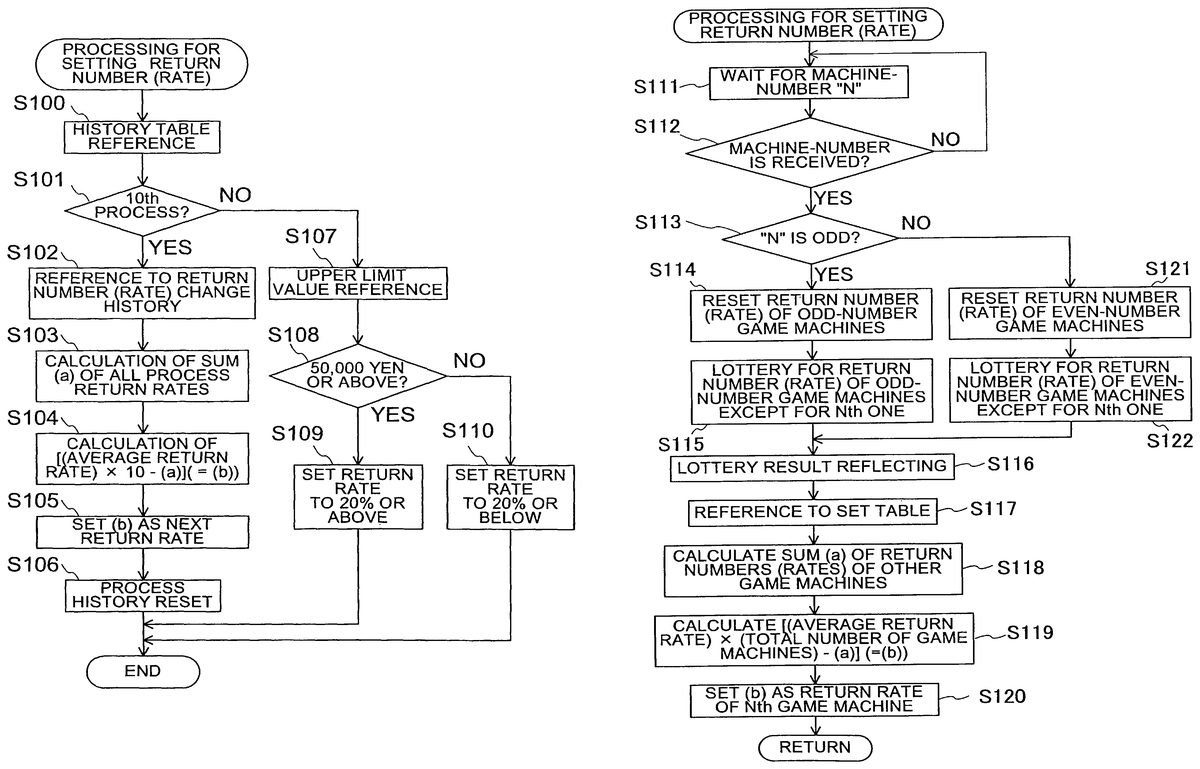
FIG. 14is a flowchart showing the flow of operation when a server sets a return rate. This flowchart corresponds to the subroutine of the return processing (step S30) shown inFIG. 7.
For setting a return rate, there are for example (i) a method of directly using a return rate preset per game machine; and (ii) a method of changing the return rates of game machines at a predetermined timing. The first preferred embodiment employs the latter method suited for providing players with more thrill.
Referring toFIG. 14, the CPU51with the server1firstly refers to a game history table (step S100). The game history table indicates the past play circumstances of each game machine2that is stored in the database54with the server1. One example of this is shown inFIG. 15. In order to refer to this history table, it is necessary that a game machine2send the server1a machine-number assigned to the game machine2. The server1reads the machine-number received by the CPU51, and refers to a history table corresponding to the read machine-number.
Referring toFIG. 15, the following contents are recorded in the game history table, assuming that one process is a term between when a certain value is set as an upper limit value of the game machine2and when this upper limit value is changed to other value. The upper limit, return rate, the presence of return, the amount of return, and setting time of return rate are recorded per process. Thus, the server1collectively controls the return rates etc. of the game machines2, and sets a return rate by referring to their respective control histories. On the history table given inFIG. 15, it is assumed that the return rate of the 10th process will be set.
Referring again toFIG. 14, upon completion of the reference processing to the game history table, the CPU51with the server1judges whether the following is the 10th process (step S101). The return rates of the game machines2are set such that the average return rate to be calculated in units of a predetermined number of processes (in 10 processes in the first preferred embodiment) is 40%, which is a percentage of an upper limit value. For example, as shown in the fourth process inFIG. 15, when the upper limit value is 100 (in thousands of yen) and the return rate is 70%, the return amount is 70 (in thousands of yen). In the first preferred embodiment, the aforesaid average return rate, 40%, is for purpose of illustration only and is not to be construed as a limiting value. This is true for the predetermined process number, 10 processes.
Judge that it is the return rate of the 10th process in the game machine2, the CPU51with the server1refers to a return rate change history (step S102). The term “return rate change history” is a history of the return rate changes in the respective processes recorded in the column, “return rate.” Based on the return rate change history and the average return rate, the return rate of the 10th process is determined. To achieve the reference processing to the return rate change history, the CPU51reads the history table stored in the database54.
Upon completion of the reference processing to the return change history, the CPU51with the server1calculates the sum (a) of the return rates of the processes that the CPU51referred to in step S102(step S103). For example, inFIG. 15, 10% to the first process, 20% to the second process, . . . and 110% to the ninth process. The sum of the returns rates of the first to ninth processes can be calculated by the expression: 10+20+ . . . +110.
Upon completion of the calculation processing of the return rate sum (a), the CPU51with the server1calculates term (b), (step S104), by the following expression (1):
[(Average Return Rate)×10−(a)]=(b) (1)
Term (b), a calculation result of the expression (1), is value indicating the return rate set to the 10th process. Concretely, in the first preferred embodiment, the return rates are set such that the average return rate in units of ten processes is 40%. Therefore, the return rate of the 10th process is given by the expression: 40(%)×10−(a).
Upon completion of the term (b) calculation processing, the CPU51with the server1sets the calculation result (b) as the next return rate (step S105).
The CPU51records the calculated return rate (b) in the column of return rate on the history table stored in the database54, and also sends the value of (b), as return rate data of the next following process, to the game machine2via the communication interface53, network NT, and the communication interface circuit41with the game machine2.
Upon completion of the next return rate setting processing, the CPU51with the server1resets a process history (step S106). The history table (seeFIG. 15) stored in the database54is used to keep constant the average of the return rates in units of a predetermined number of processes. Therefore, at the achievement of its purpose, it is necessary to create a new history table. This requires the reset of the currently stored process history. This processing is executed under a program stored in the memory52, based on the instruction of the CPU51.
When the judgment result of step S101is that the next return rate setting destination was not the 10th process, the CPU51with the server1refers to the upper limit value (step S107). The return rates are set to achieve a predetermined average return rate in units of a predetermined number of processes. However, in general, they are also changed depending on the upper limit value. Accordingly, the CPU51refers to the column “upper limit value” on the history table. This upper limit value is the upper limit value of the process to which the server1attempts to make setting. This value is set by the processing of step S21shown inFIG. 7, and then recorded in the history table stored in the database54.
Upon completion of the upper limit value reference processing, the CPU51with the server1judges whether the upper limit value is 50 (in thousands of yen) or more (step S108). In the first preferred embodiment, the aforesaid 50 (in thousands of yen) that is used as judgment standard for return rate setting, is for purpose of illustration only and is not to be construed as a limiting value.
When the judgment result is that the upper limit value is 50 (in thousands of yen) or more, the CPU51with the server1sets the return rate of the next following process to 20% or more (step S109). Based on the instruction of the CPU51, a lottery is performed to determine a return rate value of not less than 20%. This lottery is executed under a program that is stored in the memory52and prepared for selecting one from the group of given numeric characters (not less than 20). In the first preferred embodiment, the aforesaid 20% that is used as return rate standard, is for purpose of illustration only and is not to be construed as a limiting value.
The CPU51records the numeric character that is the lottery result, as the return rate of the next following process, in the history table stored in the database54. The return rate so determined is sent to the game machine2via the communication interface53, network NT, and the communication interface circuit41with the game machine2.
On the other hand, when the judgment result in step S108is that the upper limit value is not 50 (in thousands of yen) or more, the CPU51with the server1sets a value not more than 20%, as the return rate of the next following process (step S110). Based on the instruction of the CPU51, a lottery is performed to determine a return rate of not more than 20%. This lottery is executed under a program that is stored in the memory52and prepared for selecting one from the group of given numeric characters (not more than 20).
The CPU51records the numeric character that is the lottery result, as the return rate of the next following process, in the history table stored in the database54. The return rate so determined is sent to the game machine2via the communication interface53, network NT, and the communication interface circuit41with the game machine2. Thereafter, the CPU51terminates the return rate setting processing.
As described above, the server collectively controls the return rates of the individual game machines. It is therefore avoidable that the return rate of a certain game machine remains at an extremely high or low value. This leads to an increased efficiency of control.
Second Preferred Embodiment
A credit return system according to a second preferred embodiment of the present invention has the same characteristic features as the first preferred embodiment, except that when the server1sets the return rates of game machines2, the average value of the returns rates is kept constant at predetermined time intervals (e.g., every three hours).
FIG. 16is a flowchart showing the flow of operation when a server sets a return rate in the credit return system of the second preferred embodiment. In this flowchart, the same step numbers have been retained for similar processing which have the same content as in the flowchart shown inFIG. 14.
Referring toFIG. 16, the CPU51with the server1firstly refers to a game history table (step S100). As described above, the game history table indicates the past play circumstances of each game machine2that is stored in the database54with the server1. In order to refer to this history table, a game machine2is required to send the server1a machine-number assigned to the game machine2. The server1reads the machine-number received by the CPU51, and refers to a history table corresponding to the read machine-number. As a game history table of the game machine2, one that is given inFIG. 15is usable. Assuming that one process is a term between when a certain value is set as an upper limit value of the game machine2and when this upper limit value is changed to another value, the upper limit, return rate, presence of return, amount of return, and setting time of return rate are recorded per process in the game history table.
Upon completion of the reference processing to the game history table, the CPU51with the server1judges whether three hours has passed from the setting of the return rate of the first process (step S151). The return rates of the game machines2are set such that the average return rate to be calculated at predetermined time intervals (every three hours in the second preferred embodiment) is 40% In the second preferred embodiment, the aforesaid average return rate, 40%, and predetermined time intervals, every three hours, are for purpose of illustration only and are not to be construed as a limiting value
When the judgment result is that three hours has passed from the setting of the return rate of the first process, the CPU51with the server1refers to a return rate change history (step S102). As described by usingFIG. 15in the first preferred embodiment, the return rate change history is a history of the return rate changes in the respective processes that are recorded in the column, “return rate.” Based on the return rate change history and the average return rate, the return rate of the following next process (i.e., the 10th process) is determined. To achieve the reference processing to the return rate change history, the CPU51reads the history table stored in the database54, as described above.
Upon completion of the reference processing to the return change history, the CPU51with the server1calculates the sum (a) of the return rates of the processes (step S103). The sum of the return rates of the corresponding processes means the sum of the return rates that the CPU51referred to in step S102.
Upon completion of the calculation processing of the return rate sum (a), the CPU51with the server1calculates term (b), (step S104), by the following expression (2):
[(Average return rate)×(Number of the following processes)−(a)]=(b) (2)
The reason for multiplying the average return rate by term, (Number of the following processes), is that the average return rate of all the processes executed during about three hours has a predetermined value (e.g., 40%) when the following next process is started after an elapse of three hours.
Term (b), calculation result of the above expression (2), is value indicating the return rate set to the 10th process that is the first process after an elapse of three hours. In the second preferred embodiment, the return rates are set such that the average return rate every three hours is 40%. Therefore, the return rate of the 10th process is given by the expression: 40(%)×10−(a).
Upon completion of the term (b) calculation processing, the CPU51with the server1sets the calculation result (b) as the next return rate (step S105). Concretely, the CPU51records the calculated return rate (b) in the column “return rate” on the history table stored in the database54, and also sends the value of (b), as return rate data of the next following process, to the game machine2via the communication interface53, network NT, and the communication interface circuit41with the game machine2.
Upon completion of the next return rate setting processing, the CPU51with the server1resets a timer (not shown) of the game machine2to “0” (step S156). After an elapse of a predetermined time (three hours in the second preferred embodiment), it is required to measure time from “0” and keep the average return rate constant. Therefore, the CPU51sends a signal for resetting the timer of the game machine2to “0”, via the communication interface53, network NT, and the communication interface circuit41.
Upon completion of the processing of returning the time to “0”, the CPU51with the server1resets a process history (step S106). The history table stored in the database54is used to keep constant the average of the return rates in units of a predetermined number of processes. Therefore, at the achievement of its purpose, it is necessary to create a new history table. This requires the reset of the currently stored process history. This processing is executed under a program stored in the memory52, based on the instruction of the CPU51.
On the other hand, when the judgment result of step S151is that the time elapsing between when the return rate was set to the first process and when a return rate is set to the following next process is not more than three hours, the CPU51with the server1refers to the upper limit value (step S107). Since the return rates are set to achieve a predetermined average return rate every predetermined time intervals, they normally can also be changed depending on the upper limit value. Therefore, the CPU51refers to the column “upper limit value” on the history table. This upper limit value is the upper limit value of the process to which the server1attempts to make setting. This value is set by the processing of step S21shown inFIG. 7, and then recorded in the history table stored in the database54.
Upon completion of the upper limit value reference processing, the CPU51with the server1judges whether the upper limit value is 50 (in thousands of yen) or more (step S108). In the second preferred embodiment, the aforesaid 50 (in thousands of yen) that is used as judgment standard for return rate setting, is for purpose of illustration only and is not to be construed as a limiting value.
When the judgment result is that the upper limit value is 50 (in thousands of yen) or more, the CPU51with the server1sets the return rate of the next following process to 20% or more (step S109). Based on the instruction of the CPU51, a lottery is performed to determine a return rate value of not less than 20%. This lottery is executed under a program that is stored in the memory52and prepared for selecting one from the group of given numeric characters (not less than 20). In the second preferred embodiment, the aforesaid 20% that is used as return rate standard, is for purpose of illustration only and is not to be construed as a limiting value.
The CPU51records the numeric character that is the lottery result, as the return rate of the next following process, in the history table stored in the database54. The return rate so determined is sent to the game machine2via the communication interface53, network NT, and the communication interface circuit41with the game machine2.
On the other hand, when the judgment result in step S108is that the upper limit value is not 50 (in thousands of yen) or more, the CPU51with the server1sets a value not more than 20%, as the return rate of the next following process (step S110). Based on the instruction of the CPU51, a lottery is performed to determine a return rate of not more than 20%. This lottery is executed under a program that is stored in the memory52and prepared for selecting one from the group of given numeric characters (not more than 20).
The CPU51records the numeric character that is the lottery result, as the return rate of the next following process, in the history table stored in the database54. As described above, the return rate so determined is sent to the game machine2via the communication interface53, network NT, and the communication interface circuit41with the game machine2. Thereafter, the CPU51terminates the return rate setting processing.
As described above, the server collectively controls change in the return rates of the individual game machines. This leads to an increased efficiency of control. Further, since the return rates are properly changed as described above, players can get still higher thrill. Furthermore, since the return rates are changed such that the average return rate is kept constant under predetermined conditions, the players can perform a game without anxiety, while getting high thrill. In addition, since the average return rate is kept constant under the predetermined conditions, the game machine provider can have stable profits.
Third Preferred Embodiment
A credit return system according to a third preferred embodiment of the present invention has the same characteristic features as the first preferred embodiment, except that a server1changes the return rate of one game machine2in a game machine group under collective control of the server1, by referring to the return rates of other game machines2in the same game machine group.
FIG. 17is a flowchart showing the flow of operation when a server sets the return rates of a plurality of game machines under collective control of the server in the credit return system of the third preferred embodiment. This flowchart is used when a game machine2sends the server1a signal for urging return rate setting and the server1collectively controlling a plurality of game machines2receives the signal and sets a return rate, in the subroutine of the return processing (step S30) shown inFIG. 7.
Referring toFIG. 17, the CPU51with the server1firstly waits for machine-number N (step S111). The term “machine-number” means numbers for discriminating the game machines2. For example, in the case that the server1controls a game machine group G01comprising a plurality of game machine2, “G01-N” is appended as machine-number.
In the status of waiting for the machine-number N, the CPU51with the server1judges whether the machine-number is received at a predetermined timing (step S12). Based on the instruction of the CPU33with the game machine2, machine-number data is sent to the server1via the communication interface circuit41, network NT, and the communication interface53with the server1. For example, the machine-number is sent to the server1under the following situations: (i) when the cumulative credit consumption of the player of a game machine2reaches the upper limit; (ii) when a return is executed to the game machine2; or (iii) when the game machine2is changed into a game mode advantageous to the player (e.g., a big-prize mode).
When the judgment result is that no machine-number N is received, the CPU51with the server1returns the processing to step S111and waits for the machine-number N again.
On the other hand, when the judgment result is that the machine-number N is received, the CPU51with the server1judges whether the received machine-number N is odd (step S113). The reason for checking whether the machine-number N is odd is that the server1changes the return rate every odd or even machine-number. This method is a mere example of implementing the third preferred embodiment. In an alternative, the return rates of a plurality of game machines may not be collectively changed at a time.
When the judgment result is that the machine-number N is odd, the CPU51with the server1resets the return rates of odd machine-numbers (step S114). The game machines of odd machine-number are game machines having a machine-number wherein units and tens are odd. For the odd machine-number N, the CPU51collectively resets the return rates of odd machine-number game machines at a time and sets new return rates. This processing is executed under a program stored in the memory52, based on the instruction of the CPU51.
Upon completion of the processing for resetting the return rates of the odd machine-number game machines, the CPU51with the server1performs a lottery for determining the return rates of odd machine-number game machines2except for one having the machine-number N (step S115). This return rate lottery is executed under a program stored in the memory52, based on the instruction of the CPU51. Concretely, there is performed a random selection from a certain range of numerical characters (e.g., numeric values between 10 and 200 at five intervals). In this occasion, the average return rate of the game machine group G01is kept constant. Therefore, the numeric values prepared for lottery are arranged so as to fall within a certain range from the average return rate value.
In the processing of step S115, the return rate setting may be performed to all the game machines but the Nth game machine. In an alternative, as long as the average return rate of the entire game group is kept constant, the return rate of the Nth game machine may be set in preference to other game machines.
Upon completion of the return rate lottery processing to the odd machine-number game machines2except for the Nth one, the CPU51with the server1performs a lottery result reflecting processing (step S116). This lottery result reflecting processing means that the return rate of each game machine2determined by the lottery is set as its own return rate, and includes the following processing of: (i) sending the numeric data of the return rates from the server1to the game machines2; and (ii) writing the numeric data on a game history table. These processing are executed under a program stored in the memory52, based on the instruction of the CPU51.
Upon completion of the lottery result reflecting processing, the CPU51with the server1refers to the game history table in order to set the return rate of the Nth game machine (step S117). This game history table is a table on which the upper limit values, return rates, and data of return amount (obtained by multiplying the upper limit value and return rate) are recorded per game machine. One example of game history tables is given inFIG. 18. This game history table is stored in the database53and updated every time the setting is performed. The game history table ofFIG. 18is made assuming the case of setting the return rates of the game machines having machine-numbers G01to G10.
Upon completion of the game history table reference processing, the CPU51with the server1calculates the sum (a) of the return rates set to the game machines2(step S118). The sum (a) means the sum of the return rates of the game machines recorded in the column “return rate” on the history table that the CPU51referred to in the processing of step S117. Referring toFIG. 18, 10% to machine-number G01-01, 20% to machine-number G01-02, . . . and 110% to machine number G01-09. The sum of the returns rates of the nine game machines of machine-numbers G01-01to G01-09can be calculated by the expression: 10+20+ . . . +110.
Upon completion of the calculation processing of the return rate sum (a), the CPU51with the server1calculates term (b), (step S119), by the following expression (3):
[(Average return rate)×(Total number of game machines)−(a)]=(b) (3)
Term (b), calculation result of expression (3), is value indicating the return rate set to the game machine having machine-number G01-10. In the third preferred embodiment, the return rates are set such that the average return rate of the entire game machine group G01is 40%. Therefore, the return rate of the game machine having machine-number G01-10is given by the expression: 40(%)×10−(a).
Upon completion of the term (b) calculation processing, the CPU51with the server1sets the calculation result (b) as the return rate of the Nth game machine2(step S120). Concretely, the CPU51records the calculated return rate (b) in the column “return rate” on the history table stored in the database54, and also sends the value of (b), as return rate data of the game machine having machine-number G01-10, to the game machine2via the communication interface53, network NT, and the communication interface circuit41with the game machine2.
On the other hand, the judgment result of the processing of step S113is that the game machine number N is not odd (i.e., it is even), the CPU51with the server1resets the return rates of game machines having an even number (step S121). When the machine-number N is even, in preparation for new return setting, the CPU51resets the return rates of the game machines having an even machine-number at a time under a program stored in the memory52.
Upon completion of the processing for resetting the return rates of the even machine-number game machines, the CPU51with the server1performs a lottery for determining the return rates of even machine-number game machines2except for one having machine-number N (step S122). This return rate lottery is executed under a program stored in the memory52, based on the instruction of the CPU51. Concretely, there is performed a random selection from a certain range of numerical characters (e.g., numeric values between 10 and 200 at five intervals). In this occasion, the average return rate of the game machine group G01is kept constant. Therefore, the numeric values prepared for lottery are arranged so as to fall within a certain range from the average return rate value. Thereafter, the CPU51moves the processing to step S116and later steps.
Passing through the above-mentioned sequence of processing, the return rate setting processing is terminated.
Thus, the server changes the return rate of one game machine depending on the return rates of other game machines, while keeping constant the average return rate of the game machine group under collective control of the server. This increases the efficiency of control of the individual game machines of the game machine group. Further, players will pay attention to the return rate change, thereby making a game more thrilling. In addition, the return rates are not merely changed and, when other game machines of the same game machine group have a low return rate, the return rate of a certain game machine in the same group might be 100% or more. In this occasion, if the player of this game machine reaches the upper limit, the player might have the amount of return exceeding the throw-in amount till then. This produces high game characteristics.
The third preferred embodiment was presented on assumption that one process means the term between when any game machine of a game machine group receives a big prize or reaches the upper limit and when any other game machine of the same game machine group receives a big prize or reaches the upper limit, and the return rates are set so as to keep constant the average return rate per process in the game machine group. In an alternative, the setting of the return rates may be performed so as to keep constant the average return rate of the game machine group at predetermined time intervals.
Fourth Preferred Embodiment
A credit return system according to a fourth preferred embodiment has the same characteristic features as the first-preferred embodiment, except the following points: (i) in a game center (hall) comprising a plurality of game machine groups G01, G02, . . . G10, a game control server1collectively controls these game machine groups; and (ii) the game control server1changes all the return rates of a certain game machine group among these game machine groups G01, G02, . . . G10, while referring to the return rate of the entire hall.
FIG. 19is a diagram showing, in simplified form, the configuration of the credit return system of the fourth preferred embodiment. Referring toFIG. 19, the game machines2in this credit return system fall into any one of the game machine groups G01, G02, . . . G10.
The game machine groups G01, G02, . . . G10are connected to the game control server1via a network NT. A variety of information can be sent to and received from the game server1via the network NT. The term “game center” is to be interpreted in a concept as including these game machine groups G01, G02, . . . G10and the game control server1.
The game control server1collectively controls these game machine groups G01, G02, . . . G10. Based on machine-group numbers being individual to these game machine groups, the game control server1judges the source of data sent from these game groups. On the other hand, machine-numbers are respectively assigned to the game machines2constituting the game machine groups G01, . . . G10. Therefore, when sending data to these game machine groups and game machines2, the game control server1designates a target game machine group G01, G02, . . . or G10, and designates a target game machine2, by using the above-mentioned discrimination numbers.
Data sent from the game machines2include (i) discrimination numbers being individual to the game machines2, and (ii) information for identifying the players of the game machines2. Based on these information, the game control server1judges whether (i) a game machine2is in play; and (ii) the player of the game machine2is changed to other player.
In the following description, the game control server is merely referred to as a “server.”
FIG. 20is a flowchart showing the flow of operation when a server sets the return rates of a plurality of game machine groups under collective control of the server. This flowchart is used when game machine groups G01, G02, . . . G10send the server1signals for urging the setting of return rates and the server1receives the signals and sets the return rates, in the subroutine of the return processing (step S30) shown inFIG. 7.
Referring toFIG. 20, the server1firstly waits for game machine group number N (step S131). The game machine group number is a number assigned for discriminating the game machine groups G01, G02, . . . G10. Therefore, the game machines2constituting these game machine groups are numbered differently. For example, they have the following discrimination numbers: “G01-01”, “G03-02”, “G10-03”, the first portion of which (e.g., “G01”) indicates a machine group and a second portion (e.g., “01”) indicates a machine-number.
While waiting for the game machine group number N, the CPU51with the server1judges whether the game machine group number N is received at a predetermined timing (step S132). This judgment processing is achieved by the CPU51with the server1. Therefore, under the instruction of the CPU33with a game machine2of a certain game machine group, its machine-number data is sent to the CPU51via the communication interface circuit41, network NT, and the communication interface53with the server1. The CPU51receives the machine-number data and reads its game machine group part. This game machine group number and machine-number are sent to the server1at a predetermined timing, such as (i) when the cumulative credit consumption of the player of the game machine2reaches the upper limit; (ii) after a return is executed to the game machine2; or (iii) when the game machine2is changed into a game status advantageous to the player, e.g., a big prize mode.
When the judgment result is that the game machine group number N is not received, the CPU51with the server1returns the processing to step S131, and waits for a game machine group number again.
On the other hand, when the judgment result is that the game machine number N is received, the CPU51with the server1judges whether the received game machine number N is odd (step S133). The reason for checking whether the game machine group N is odd is that the server1changes the return rate every odd or even game machine group. This method is a mere example of implementing the fourth preferred embodiment. In an alternative, the return rates of a plurality of game machine groups may not be collectively changed at a time.
When the judgment result is that the game machine group N is odd, the CPU51with the server1resets the return rates of odd game machine groups (step S134). The odd game machine groups have a discrimination number wherein the units and tens of the first portion are odd. For the odd game machine group number N, the CPU51collectively resets the return rates of the odd game machine groups at a time and sets their new return rates. This processing is executed under a program stored in the memory52, based on the instruction of the CPU51.
Upon completion of the processing for resetting the return rates of the odd game machine groups, the CPU51with the server1performs a lottery for determining the return rates of all the odd game machine groups but one having the game machine group number N (step S135). This return rate lottery is executed under a program stored in the memory52, based on the instruction of the CPU51. Concretely, there is performed a random selection from a certain range of numerical characters (e.g., numeric values between 10 and 200 at five intervals). In this occasion, the average return rate of all the plurality of game machine groups under control of the server1(i.e., the entire game center) is kept constant. Therefore, the numeric values prepared for lottery are arranged so as to fall within a certain range from the average return rate value.
In the processing of step S135, the return rate setting may be performed to all the game machine groups but the Nth game machine group. In an alternative, as long as the average return rate of the entire hall is kept constant, the return rate of the Nth game machine group may be set in preference to other game machine groups.
Upon completion of the return rate lottery processing to the odd game machine groups except for the Nth one, the CPU51with the server1performs a lottery result reflecting processing (step S136). This lottery result reflecting processing means that the return rate of each game machine group determined by the lottery is set as its own return rate, and includes the following processing of: (i) sending the numeric data of the return rates from the server1to the game machine groups G01, G02, . . . G10; and (ii) writing the numeric data on a game history table. These processing are executed under a program stored in the memory52, based on the instruction of the CPU51.
Upon completion of the lottery result reflecting processing, the CPU51with the server1refers to the game history table in order to set the return rate of the Nth game machine group (step S137). This game history table is a table on which the upper limit values, return rates, and data of return amount (obtained by multiplying the upper limit value and return rate) are recorded per game machine group. One example of game history tables is given inFIG. 21. This game history table is stored in the database53and updated every time the setting is performed. The game history table ofFIG. 21is made assuming the case of setting the return rates of the game machine group G10.
Upon completion of the game history table reference processing, the CPU51with the server1calculates the sum (a) of the return rates set to the game machine groups G01, G02, . . . G10(step S138). The sum (a) means the sum of the return rates of the game machine groups recorded in the column “return rate” on the history table that the CPU51referred to in the processing of step S137. Referring toFIG. 21, 10% to game machine group G01, 20% to G02, . . . and 110% to G09. The sum of the returns rates of the nine game machine groups of G01to G09can be calculated by the expression: 10+20+ . . . +110.
Upon completion of the calculation processing of the return rate sum (a), the CPU51with the server1calculates term (b), (step S139), by the following expression (4):
[(Average return rate)×(Total number of game machine groups)−(a)]=(b) (4)
Term (b), calculation result of expression (4), is value indicating the return rate set to the game machine group G10. In the fourth preferred embodiment, the return rates are set such that the average return rate of the entire hall is 40%. Therefore, the return rate of the game machine group G10is given by the expression: 40(%)×10−(a).
Upon completion of the term (b) calculation processing, the CPU51with the server1sets the calculation result (b) as the return rate of the Nth game machine group (step S140). Concretely, the CPU51records the calculated return rate (b) in the column “return rate” on the history table stored in the database54. The CPU51also sends the value of (b), as return rate data of the game machine group G10, to the game machines2of the game machine group G10, via the communication interface53, network NT, and the communication interface circuits41with the game machines2.
On the other hand, the judgment result of the processing of step S133is that the game machine group number N is not odd (i.e., it is even), the CPU51with the server1resets the return rates of game machine groups having an even number (step S141). In preparation for new return setting, the CPU51resets the return rates of the even game machine groups at a time under a program stored in the memory52.
Upon completion of the processing for resetting the return rates of the even game machine groups, the CPU51with the server1performs a lottery for determining the return rates of all the even game machine groups but one having the game machine number N (step S142). This return rate lottery is executed under a program stored in the memory52, based on the instruction of the CPU51. Concretely, there is performed a random selection from a certain range of numerical characters (e.g., numeric values between 10 and 200 at five intervals). In this occasion, the average return rate of the entire hall is kept constant. Therefore, the numeric values prepared for lottery are arranged so as to fall within a certain range from the average return rate value. Thereafter, the CPU51moves the processing to step S136and later steps.
Passing through the above-mentioned sequence of processing, the return rate setting processing is terminated.
Thus, the game control server changes the return rates of one game machine group depending on the return rates of other game machine groups, while keeping constant the average return rate of the entire game center comprising the plurality of game machine groups under collective control of the game control server. This increases the efficiency of control of the individual game machine groups and individual game machines in the game center. In addition, the game control server changes the entire return rate of one game machine group in the plurality of game machine groups under control of the server, depending on the return rates of other game machine groups. This produces a high stage effect in the entire game center having many game machine groups. This may be the case when, for example, a player performs a game with a game machine of a certain game machine group, and the return rate of an adjacent game machine group is changed to over 100%, this player might move to the adjacent group. At the result, player movement might occur across the game center. On the contrary, if no player movement occurs, the average return rate of the entire game center is kept constant. Therefore, players also pay attention to a return rate change in other game machine groups. Concretely, when the return rate of a game machine group where one player performs a game is increased, this player will be under the eyes of other players and have a sense of superiority at the arrival at the upper limit.
The fourth preferred embodiment was presented on assumption that one process means the term between when any game machine of a game center receives a big prize or reaches the upper limit and when the following next game machine of the game center receives a big prize or reaches the upper limit, and the return rates are set so as to keep constant the average return rate per process in the game center. In an alternative, the setting of the return rates may be performed so as to keep constant the average return rate of the entire game center at predetermined time intervals.
Although in the fourth preferred embodiment, the average return rate is kept constant per game center comprising a plurality of game machine groups, a game center group comprising a plurality of game centers may be collectively controlled so as to keep constant the average return rate of the game center group. In this case, if a game machine provider has a plurality of places (game centers) to provide game machines across many communities, there can be a high possibility that players perform games while changing from game center to game center. This is advantageous to the game machine provider.
While but the first to fourth preferred embodiments of the invention have been shown and described, it will be understood that many changes and modifications may be made therein without departing from the spirit or scope of the present invention.
Claims
- A game server for collectively controlling a game machine group comprising a plurality of game machines which are brought into a status enabling to start a game based on coin throwing or a given credit number and are given payout according to a result of said game, said game server including: return means that judges, based on information of credit consumption on a game machine where a player performs a game, cumulative credit consumption of said player and, when a judgment result is that said cumulative credit consumption reaches a predetermined upper limit, executes a return based on a predetermined return rate or based on a result of lottery for determining whether the return is to be executed, said return being executed regardless of a game result;and a first sending means for sending said game machine a signal that changes the return rate value of said game machine of said game machine group depending on return rate values of other game machines, wherein the return rate value is set by the return means in reference to a game history of the game machine and history of the return rate value change by calculating a sum of process return rates, and calculating and setting as the return rate a product of an average return rate times N, minus the sum of process return rates, so that the return rate value of the gaming machine that is within the game machine group is changed in reference to the return rate value of the game machine group, N being a predetermined number of processes.
- The game server according to claim 1 further including: receiving means for receiving game information about game situations in each game machine of said game machine group;and a second sending means for sending, based on contents of said game information, a signal for displaying the value of said predetermined return rate on a display part of said each game machine.
- The game server according to claim 1 further including: a third sending means for sending said game machine a control signal for keeping constant an average return rate value of said game machine group, under predetermined conditions.
- The game server according to claim 3 wherein said predetermined conditions are based on either predetermined period of time or predetermined number of processes, each of the processes comprising processing that after a first game machine of said game machine group reaches said predetermined upper limit, a cumulative credit consumption on any one game machine of said game machine group that includes said first game machine reaches said predetermined upper limit.
- A game machine that is one of a plurality of game machines forming a game machine group under a collective control of a game server, which are brought into a status enabling to start a game based on coin throwing or a given credit number and are given payout according to a result of said game, said game machine including: return means that executes a return, when cumulative credit consumption reaches a predetermined upper limit, based on a predetermined return rate or based on a result of lottery for determining whether the return is to be executed, said return being executed regardless of a game result;and change means that receives a signal sent from said game server and changes the return rate value of said game machine of said game machine group, depending on return rates of other game machines of said game machine group, wherein the return rate value is set by the return means in reference to a game history of the game machine and history of the return rate value change by calculating a sum of process return rates, and calculating and setting as the return rate a product of an average return rate times N, minus the sum of process return rates, so that the return rate value of the gaming machine that is within the game machine group is changed in reference to the return rate value of the game machine group, N being a predetermined number of processes.
- The game machine according to claim 5 further including: sending means for sending game information about game situations;and display means that receives a signal sent from said game server and displays the value of said predetermined return rate on a display part, based on contents of said game information.
- The game machine according to claim 5 wherein said change means changes the return rate value while keeping an average value of the return rates, under predetermined conditions.
- The game machine according to claim 7 wherein said predetermined conditions are based on either predetermined period of time or predetermined number of processes, each of the processes comprising processing that after a first game machine of said game machine group reaches said predetermined upper limit, a cumulative credit consumption on any one game machine of said game machine group that includes said first game machine reaches said predetermined upper limit.
- A game control method of collectively controlling a game machine group comprising a plurality of game machines which are brought into a status enabling to start a game based on coin throwing or a given credit number and which are given payout according to a result of said game, said game control method including: a check step for checking cumulative credit consumptions on said plurality of game machines;a return step of executing a return with a game machine, when it is determined that cumulative credit consumption of said game machine reaches a predetermined upper limit in the check step, based on a predetermined return rate or based on a result of lottery for determining whether the return is to be executed, said return being executed regardless of a game result;and a first sending step for sending said game machine a signal that changes the return rate value of said game machine of said game machine group depending on return rate values of other game machines, wherein the return rate value is set by the return step in reference to a game history of the game machine and history of the return rate value change by calculating a sum of process return rates, and calculating and setting as the return rate a product of an average return rate times N, minus the sum of process return rates, so that the return rate value of the gaming machine that is within the game machine group is changed in reference to the return rate value of the game machine group, N being a predetermined number of processes.
- The game control method according to claim 9 further including: a receiving step for receiving game information about game situations of each game machine of said game machine group;and a second sending step for sending a signal for displaying the value of said predetermined return rate on a display part of said each game machine.
- The game control method according to claim 9 further including: a third sending step for sending said game machine a control signal for keeping constant an average return rate value of said game machine group, under predetermined conditions.
- The game control method according to claim 11 wherein said predetermined conditions are based on either predetermined period of time or predetermined number of processes, each of the processes comprising processing that after a first game machine of said game machine group reaches said predetermined upper limit, a cumulative credit consumption on any one game machine of said game machine group that includes said first game machine reaches said predetermined upper limit.
- A game server for collectively controlling a game machine group comprising a plurality of game machines that are brought into a status enabling to start a game based on coin throwing or a given credit number and are given payout according to a result of said game, said game server including: a processor programmed to judge, based on information of credit consumption on a game machine where a player performs a game, cumulative credit consumption of said player and, when a judgment result is that said cumulative credit consumption reaches a predetermined upper limit, executes a return based on a predetermined return rate or based on a result of lottery for determining whether the return is to be executed, said return being executed regardless of a game result;and an interface through which said processor sends a signal that changes the return rate value of said game machine of said game machine group depending on return rate values of other game machines, wherein the return rate value is set by the processor in reference to a game history of the game machine and history of the return rate value change by calculating a sum of process return rates, and calculating and setting as the return rate a product of an average return rate times N, minus the sum of process return rates, so that the return rate value of the gaming machine that is within the game machine group is changed in reference to the return rate value of the game machine group, N being a predetermined number of processes.
- A game server for collectively controlling a game machine group comprising a plurality of game machines which are brought into a status enabling to start a game based on coin throwing or a given credit number and are given payout according to a result of said game, said game server including: return means that judges, based on information of credit consumption on a game machine where a player performs a game, cumulative credit consumption of said player and, when a judgment result is that said cumulative credit consumption reaches a predetermined upper limit, executes a return based on a predetermined return rate or based on a result of lottery for determining whether the return is to be executed, said return being executed regardless of a game result;and a first sending means for sending said game machine a signal that changes the return rate value of said game machine of said game machine group depending on return rate values of other game machines, wherein the return rate value is set by the return means in reference to a game history of the game machine and history of the return rate value change by calculating a sum of return rates of other game machines in the game machine group, and calculating and setting as the return rate a product of an average return rate and a number of game machines in the game machine group, minus the sum of return rates, so that the return rate value of the gaming machine that is within the game machine group is changed in reference to the return rate value of the game machine group.
Disclaimer: Data collected from the USPTO and may be malformed, incomplete, and/or otherwise inaccurate.