U.S. Pat. No. 8,270,439
VIDEO GAME SYSTEM USING PRE-ENCODED DIGITAL AUDIO MIXING
AssigneeActivevideo Networks, Inc.
Issue DateJanuary 5, 2007
Illustrative Figure
Abstract
A method and related system of encoding audio is disclosed. In the method, data representing a plurality of independent audio signals is accessed. The data representing each respective audio signal comprises a sequence of source frames. Each frame in the sequence of sources frames comprises a plurality of audio data copies. Each audio data copy has an associated quality level that is a member of a predefined range of quality levels, ranging from a highest quality level to a lowest quality level. The plurality of source frame sequences is merged into a sequence of target frames that comprise a plurality of target channels. Merging corresponding source frames into a respective target frame includes selecting a quality level and assigning the audio data copy at the selected quality level of each corresponding source frame to at least one respective target channel.
Description
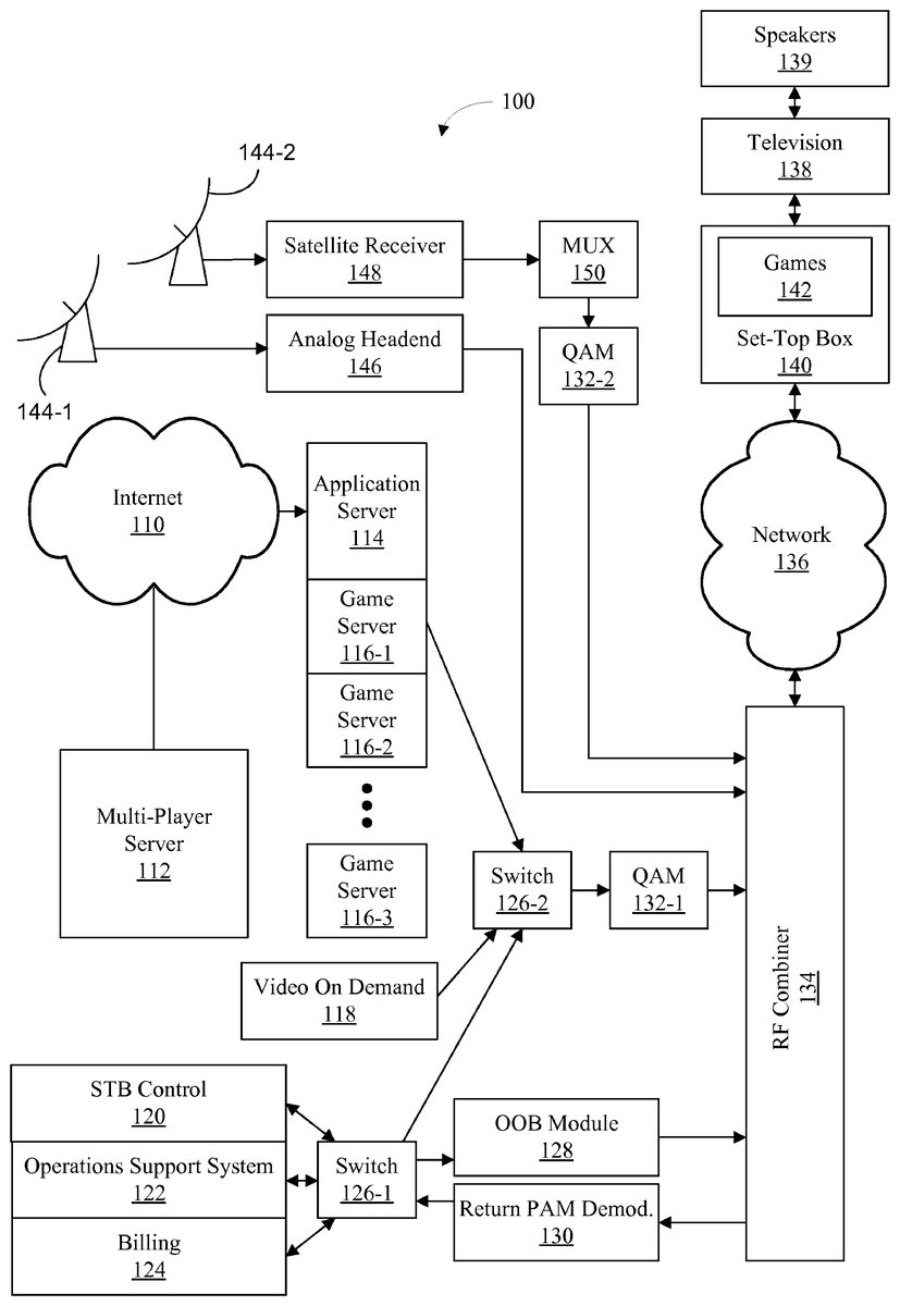
Like reference numerals refer to corresponding parts throughout the drawings. DETAILED DESCRIPTION OF EMBODIMENTS Reference will now be made in detail to embodiments, examples of which are illustrated in the accompanying drawings. In the following detailed description, numerous specific details are set forth in order to provide a thorough understanding of the present invention. However, it will be apparent to one of ordinary skill in the art that the present invention may be practiced without these specific details. In other instances, well-known methods, procedures, components, and circuits have not been described in detail so as not to unnecessarily obscure aspects of the embodiments. FIG. 1is a block diagram illustrating an embodiment of a cable television system100for receiving orders for and providing content, such as one or more video games, to one or more users (including multi-user video games). Several content data streams may be transmitted to respective subscribers and respective subscribers may, in turn, order services or transmit user actions in a video game. Satellite signals, such as analog television signals, may be received using satellite antennas144. Analog signals may be processed in analog headend146, coupled to radio frequency (RF) combiner134and transmitted to a set-top box (STB)140via a network136. In addition, signals may be processed in satellite receiver148, coupled to multiplexer (MUX)150, converted to a digital format using a quadrature amplitude modulator (QAM)132-2(such as 256-level QAM), coupled to the radio frequency (RF) combiner134and transmitted to the STB140via the network136. Video on demand (VOD) server118may provide signals corresponding to an ordered movie to switch126-2, which couples the signals to QAM132-1for conversion into the digital format. These digital signals are coupled to the radio frequency (RF) combiner134and transmitted to the STB140via the network136. The STB140may display one or more video signals, including those corresponding to video-game content discussed below, on television or ...
Like reference numerals refer to corresponding parts throughout the drawings.
DETAILED DESCRIPTION OF EMBODIMENTS
Reference will now be made in detail to embodiments, examples of which are illustrated in the accompanying drawings. In the following detailed description, numerous specific details are set forth in order to provide a thorough understanding of the present invention. However, it will be apparent to one of ordinary skill in the art that the present invention may be practiced without these specific details. In other instances, well-known methods, procedures, components, and circuits have not been described in detail so as not to unnecessarily obscure aspects of the embodiments.
FIG. 1is a block diagram illustrating an embodiment of a cable television system100for receiving orders for and providing content, such as one or more video games, to one or more users (including multi-user video games). Several content data streams may be transmitted to respective subscribers and respective subscribers may, in turn, order services or transmit user actions in a video game. Satellite signals, such as analog television signals, may be received using satellite antennas144. Analog signals may be processed in analog headend146, coupled to radio frequency (RF) combiner134and transmitted to a set-top box (STB)140via a network136. In addition, signals may be processed in satellite receiver148, coupled to multiplexer (MUX)150, converted to a digital format using a quadrature amplitude modulator (QAM)132-2(such as 256-level QAM), coupled to the radio frequency (RF) combiner134and transmitted to the STB140via the network136. Video on demand (VOD) server118may provide signals corresponding to an ordered movie to switch126-2, which couples the signals to QAM132-1for conversion into the digital format. These digital signals are coupled to the radio frequency (RF) combiner134and transmitted to the STB140via the network136.
The STB140may display one or more video signals, including those corresponding to video-game content discussed below, on television or other display device138and may play one or more audio signals, including those corresponding to video-game content discussed below, on speakers139. Speakers139may be integrated into television138or may be separate from television138. WhileFIG. 1illustrates one subscriber STB140, television or other display device138, and speakers139, in other embodiments there may be additional subscribers, each having one or more STBs, televisions or other display devices, and/or speakers.
The cable television system100may also include an application server114and a plurality of game servers116. The application server114and the plurality of game servers116may be located at a cable television system headend. While a single instance or grouping of the application server114and the plurality of game servers116is illustrated inFIG. 1, other embodiments may include additional instances in one or more headends. The servers and/or other computers at the one or more headends may run an operating system such as Windows, Linux, Unix, or Solaris.
The application server114and one or more of the game servers116may provide video-game content corresponding to one or more video games ordered by one or more users. In the cable television system100there may be a many-to-one correspondence between respective users and an executed copy of one of the video games. The application server114may access and/or log game-related information in a database. The application server114may also be used for reporting and pricing. One or more game engines (also called game engine modules)248(FIG. 2) in the game servers116are designed to dynamically generate video-game content using pre-encoded video and/or audio data. In an exemplary embodiment, the game servers116use video encoding that is compatible with an MPEG compression standard and use audio encoding that is compatible with the AC-3 compression standard.
The video-game content is coupled to the switch126-2and converted to the digital format in the QAM132-1. In an exemplary embodiment with 256-level QAM, a narrowcast sub-channel (having a bandwidth of approximately 6 MHz, which corresponds to approximately 38 Mbps of digital data) may be used to transmit 10 to 30 video-game data streams for a video game that utilizes between 1 and 4 Mbps.
These digital signals are coupled to the radio frequency (RF) combiner134and transmitted to STB140via the network136. The application server114may also access, via Internet110, persistent player or user data in a database stored in multi-player server112. The application server114and the plurality of game servers116are further described below with reference toFIG. 2.
The STB140may optionally include a client application, such as games142, that receives information corresponding to one or more user actions and transmits the information to one or more of the game servers116. The game applications142may also store video-game content prior to updating a frame of video on the television138and playing an accompanying frame of audio on the speakers139. The television138may be compatible with an NTSC format or a different format, such as PAL or SECAM. The STB140is described further below with reference toFIG. 3.
The cable television system100may also include STB control120, operations support system122and billing system124. The STB control120may process one or more user actions, such as those associated with a respective video game, that are received using an out-of-band (OOB) sub-channel using return pulse amplitude (PAM) demodulator130and switch126-1. There may be more than one OOB sub-channel. While the bandwidth of the OOB sub-channel(s) may vary from one embodiment to another, in one embodiment, the bandwidth of each OOB sub-channel corresponds to a bit rate or data rate of approximately 1 Mbps. The operations support system122may process a subscriber's order for a respective service, such as the respective video game, and update the billing system124. The STB control120, the operations support system122and/or the billing system124may also communicate with the subscriber using the OOB sub-channel via the switch126-1and the OOB module128, which converts signals to a format suitable for the OOB sub-channel. Alternatively, the operations support system122and/or the billing system124may communicate with the subscriber via another communications link such as an Internet connection or a communications link provided by a telephone system.
The various signals transmitted and received in the cable television system100may be communicated using packet-based data streams. In an exemplary embodiment, some of the packets may utilize an Internet protocol, such as User Datagram Protocol (UDP). In some embodiments, networks, such as the network136, and coupling between components in the cable television system100may include one or more instances of a wireless area network, a local area network, a transmission line (such as a coaxial cable), a land line and/or an optical fiber. Some signals may be communicated using plain-old-telephone service (POTS) and/or digital telephone networks such as an Integrated Services Digital Network (ISDN). Wireless communication may include cellular telephone networks using an Advanced Mobile Phone System (AMPS), Global System for Mobile Communication (GSM), Code Division Multiple Access (CDMA) and/or Time Division Multiple Access (TDMA), as well as networks using an IEEE 802.11 communications protocol, also known as WiFi, and/or a Bluetooth communications protocol.
WhileFIG. 1illustrates a cable television system, the system and methods described may be implemented in a satellite-based system, the Internet, a telephone system and/or a terrestrial television broadcast system. The cable television system100may include additional elements and/or remove one or more elements. In addition, two or more elements may be combined into a single element and/or a position of one or more elements in the cable television system100may be changed. In some embodiments, for example, the application server114and its functions may be merged with and into the game servers116.
FIG. 2is a block diagram illustrating an embodiment of a video-game system200. The video-game system200may include at least one data processor, video processor and/or central processing unit (CPU)210, one or more optional user interfaces214, a communications or network interface220for communicating with other computers, servers and/or one or more STBs (such as the STB140inFIG. 1), memory222and one or more signal lines212for coupling these components to one another. The at least one data processor, video processor and/or central processing unit (CPU)210may be configured or configurable for multi-threaded or parallel processing. The user interface214may have one or more keyboards216and/or displays218. The one or more signal lines212may constitute one or more communications busses.
Memory222may include high-speed random access memory and/or non-volatile memory, including ROM, RAM, EPROM, EEPROM, one or more flash disc drives, one or more optical disc drives and/or one or more magnetic disk storage devices. Memory222may store an operating system224, such as LINUX, UNIX, Windows, or Solaris, that includes procedures (or a set of instructions) for handling basic system services and for performing hardware dependent tasks. Memory222may also store communication procedures (or a set of instructions) in a network communication module226. The communication procedures are used for communicating with one or more STBs, such as the STB140(FIG. 1), and with other servers and computers in the video-game system200.
Memory222may also include the following elements, or a subset or superset of such elements, including an applications server module228(or a set of instructions), a game asset management system module230(or a set of instructions), a session resource management module234(or a set of instructions), a player management system module236(or a set of instructions), a session gateway module242(or a set of instructions), a multi-player server module244(or a set of instructions), one or more game server modules246(or sets of instructions), an audio signal pre-encoder264(or a set of instructions), and a bank256for storing macro-blocks and pre-encoded audio signals. The game asset management system module230may include a game database232, including pre-encoded macro-blocks, pre-encoded audio signals, and executable code corresponding to one or more video games. The player management system module236may include a player information database240including information such as a user's name, account information, transaction information, preferences for customizing display of video games on the user's STB(s)140(FIG. 1), high scores for the video games played, rankings and other skill level information for video games played, and/or a persistent saved game state for video games that have been paused and may resume later. Each instance of the game server module246may include one or more game engine modules248. Game engine module248may include games states250corresponding to one or more sets of users playing one or more video games, synthesizer module252, one or more compression engine modules254, and audio frame merger255. The bank256may include pre-encoded audio signals257corresponding to one or more video games, pre-encoded macro-blocks258corresponding to one or more video games, and/or dynamically generated or encoded macro-blocks260corresponding to one or more video games.
The game server modules246may run a browser application, such as Windows Explorer, Netscape Navigator or FireFox from Mozilla, to execute instructions corresponding to a respective video game. The browser application, however, may be configured to not render the video-game content in the game server modules246. Rendering the video-game content may be unnecessary, since the content is not displayed by the game servers, and avoiding such rendering enables each game server to maintain many more game states than would otherwise be possible. The game server modules246may be executed by one or multiple processors. Video games may be executed in parallel by multiple processors. Games may also be implemented in parallel threads of a multi-threaded operating system.
AlthoughFIG. 2shows the video-game system200as a number of discrete items,FIG. 2is intended more as a functional description of the various features which may be present in a video-game system rather than as a structural schematic of the embodiments described herein. In practice, and as recognized by those of ordinary skill in the art, the functions of the video-game system200may be distributed over a large number of servers or computers, with various groups of the servers performing particular subsets of those functions. Items shown separately inFIG. 2could be combined and some items could be separated. For example, some items shown separately inFIG. 2could be implemented on single servers and single items could be implemented by one or more servers. The actual number of servers in a video-game system and how features, such as the game server modules246and the game engine modules248, are allocated among them will vary from one implementation to another, and may depend in part on the amount of information stored by the system and/or the amount of data traffic that the system must handle during peak usage periods as well as during average usage periods. In some embodiments, audio signal pre-encoder264is implemented on a separate computer system, which may be called a pre-encoding system, from the video game system(s)200.
Furthermore, each of the above identified elements in memory222may be stored in one or more of the previously mentioned memory devices. Each of the above identified modules corresponds to a set of instructions for performing a function described above. The above identified modules or programs (i.e., sets of instructions) need not be implemented as separate software programs, procedures or modules, and thus various subsets of these modules may be combined or otherwise re-arranged in various embodiments. In some embodiments, memory222may store a subset of the modules and data structures identified above. Memory222also may store additional modules and data structures not described above.
FIG. 3is a block diagram illustrating an embodiment of a set top box (STB)300, such as STB140(FIG. 1). STB300may include at least one data processor, video processor and/or central processing unit (CPU)310, a communications or network interface314for communicating with other computers and/or servers such as video game system200(FIG. 2), a tuner316, an audio decoder318, an audio driver320coupled to speakers322, a video decoder324, and a video driver326coupled to a display328. STB300also may include one or more device interfaces330, one or more IR interfaces334, memory340and one or more signal lines312for coupling components to one another. The at least one data processor, video processor and/or central processing unit (CPU)310may be configured or configurable for multi-threaded or parallel processing. The one or more signal lines312may constitute one or more communications busses. The one or more device interfaces330may be coupled to one or more game controllers332. The one or more IR interfaces334may use IR signals to communicate wirelessly with one or more remote controls336.
Memory340may include high-speed random access memory and/or non-volatile memory, including ROM, RAM, EPROM, EEPROM, one or more flash disc drives, one or more optical disc drives, and/or one or more magnetic disk storage devices. Memory340may store an operating system342that includes procedures (or a set of instructions) for handling basic system services and for performing hardware dependent tasks. The operating system342may be an embedded operating system such as Linux, OS9 or Windows, or a real-time operating system suitable for use on industrial or commercial devices, such as VxWorks by Wind River Systems, Inc. Memory340may store communication procedures (or a set of instructions) in a network communication module344. The communication procedures are used for communicating with computers and/or servers such as video game system200(FIG. 2). Memory340may also include control programs346(or a set of instructions), which may include an audio driver program348(or a set of instructions) and a video driver program350(or a set of instructions).
STB300transmits order information and information corresponding to user actions and receives video-game content via the network136. Received signals are processed using network interface314to remove headers and other information in the data stream containing the video-game content. Tuner316selects frequencies corresponding to one or more sub-channels. The resulting audio signals are processed in audio decoder318. In some embodiments, audio decoder318is an AC-3 decoder. The resulting video signals are processed in video decoder324. In some embodiments, video decoder314is an MPEG-1, MPEG-2, MPEG-4, H.262, H.263, H.264, or VC-1 decoder; in other embodiments, video decoder314may be an MPEG-compatible decoder or a decoder for another video-compression standard. The video content output from the video decoder314is converted to an appropriate format for driving display328using video driver326. Similarly, the audio content output from the audio decoder318is converted to an appropriate format for driving speakers322using audio driver320. User commands or actions input to the game controller332and/or the remote control336are received by device interface330and/or by IR interface334and are forwarded to the network interface314for transmission.
The game controller332may be a dedicated video-game console, such as those provided by Sony Playstation®, Nintendo®, Sega® and Microsoft Xbox®, or a personal computer. The game controller332may receive information corresponding to one or more user actions from a game pad, keyboard, joystick, microphone, mouse, one or more remote controls, one or more additional game controllers or other user interface such as one including voice recognition technology. The display328may be a cathode ray tube, a liquid crystal display, or any other suitable display device in a television, a computer or a portable device, such as a video game controller332or a cellular telephone. In some embodiments, speakers322are embedded in the display328. In some embodiments, speakers322include left and right speakers respectively positioned to the left and right of the displays328. In some embodiments, in addition to left and right speakers, speakers322include a center speaker. In some embodiments, speakers322include surround-sound speakers positioned behind a user.
In some embodiments, the STB300may perform a smoothing operation on the received video-game content prior to displaying the video-game content. In some embodiments, received video-game content is decoded, displayed on the display328, and played on the speakers322in real time as it is received. In other embodiments, the STB300stores the received video-game content until a full frame of video is received. The full frame of video is then decoded and displayed on the display328while accompanying audio is decoded and played on speakers322.
AlthoughFIG. 3shows the STB300as a number of discrete items,FIG. 3is intended more as a functional description of the various features which may be present in a set top box rather than as a structural schematic of the embodiments described herein. In practice, and as recognized by those of ordinary skill in the art, items shown separately inFIG. 3could be combined and some items could be separated. Furthermore, each of the above identified elements in memory340may be stored in one or more of the previously mentioned memory devices. Each of the above identified modules corresponds to a set of instructions for performing a function described above. The above identified modules or programs (i.e., sets of instructions) need not be implemented as separate software programs, procedures or modules, and thus various subsets of these modules may be combined or otherwise re-arranged in various embodiments. In some embodiments, memory340may store a subset of the modules and data structures identified above. Memory340also may store additional modules and data structures not described above.
FIG. 4is a flow diagram illustrating a process400for encoding audio in accordance with some embodiments. In some embodiments, process400is performed by a video game system such as video game system200(FIG. 2). Alternately, process400is performed in a distinct computer system and the resulting encoded audio data is transferred to or copied to one or more video game systems200. Audio data is received from a plurality of independent sources (402). In some embodiments, audio data is received from each independent source in the form of a pulse-code-modulated bitstream, such as a .wav file (404). In some embodiments, the audio data received from independent sources include audio data corresponding to background music for a video game and audio data corresponding to various sound effects for a video game.
Audio data from each independent source is encoded into a sequence of source frames, thus producing a plurality of source frame sequences (406). In some embodiments, an audio signal pre-encoder such as audio signal pre-encoder264of video game system200(FIG. 2) or of a separate computer system encodes the audio data from each independent source. In some embodiments, for a frame in the sequence of source frames, a plurality of copies of the frame is generated (408). Each copy has a distinct associated quality level that is a member of a predefined range of quality levels that range from a highest quality level to a lowest quality level. In some embodiments, the associated quality levels correspond to specified signal-to-noise ratios (410). In some embodiments, the number of bits consumed by each copy decreases with decreasing associated quality level. The resulting plurality of source frame sequences is stored in memory for later use, e.g., during performance of an interactive video game.
During performance of a video game or other interactive program, two or more of the plurality of source frame sequences are merged into a sequence of target frames (412). The target frames comprise a plurality of independent target channels. In some embodiments, an audio frame merger such as audio frame merger255of game server module246(FIG. 2) merges the two or more source frame sequences. In some embodiments, a signal-to-noise ratio for a source frame is selected (414). For example, a signal-to-noise ratio is selected to maintain a constant bit rate for the sequence of target frames. In some embodiments, the selected signal-to-noise ratio is the highest signal-to-noise ratio at which the constant bit rate can be maintained. In some embodiments, however, the bit rate for the sequence of target frames may change dynamically between frames. In some embodiments, the copy of the source frame having the selected signal-to-noise ratio is merged into a target frame in the sequence of target frames (416). In some embodiments, the target frame is in the AC-3 format.
The sequence of target frames may be transmitted from a server system such as video game system200(FIG. 2) to a client system such as set-top box300(FIG. 3). STB300may assign each target channel to a separate speaker or may down-mix two or more target channels into an audio stream assigned to a speaker, depending on the speaker configuration. Merging the plurality of source frames sequences into a sequence of target frames comprising a plurality of independent target channels thus enables simultaneous playback of multiple independent audio signals.
FIG. 5is a flow diagram illustrating a process500for encoding audio in accordance with some embodiments. In some embodiments, process500is performed by an audio frame merger such as audio frame merger255in video game system200(FIG. 2). Data representing a plurality of independent audio signals is accessed (502). The data representing each audio signal comprise a sequence of source frames. In some embodiments, the data representing a plurality of independent audio signals is stored as pre-encoded audio signals257in bank256of video game system200, from which the audio frame merger255can access it. The generation of the pre-encoded audio signals is discussed above with reference toFIG. 4.
In some embodiments, each source frame comprises a plurality of audio data copies (504). Each audio data copy has a distinct associated quality level that is a member of a predefined range of quality levels that range from a highest quality level to a lowest quality level. In some embodiments, the associated quality levels correspond to specified signal-to-noise ratios.
In some embodiments, two sequences of source frames are accessed. For example, a first sequence of source frames comprises a continuous source of non-silent audio data and a second sequence of source frames comprises an episodic source of non-silent audio data that includes sequences of audio data representing silence (506). In some embodiments, the first sequence may correspond to background music for a video game and the second sequence may correspond to a sound effect to be played in response to a user command. In another example, a first sequence of source frames comprises a first episodic source of non-silent audio data and a second sequence of source frames comprises a second episodic source of non-silent audio data; both sequences include sequences of audio data representing silence (505). In some embodiments, the first sequence may correspond to a first sound effect to be played in response to a first user command; the second sequence may correspond to a second sound effect, to be played in response to a second user command, which overlaps with the first sound effect. In yet another example, a first sequence of source frames comprises a first continuous source of non-silent audio data and a second sequence of source frames comprises a second continuous source of non-silent audio data. In some embodiments, the first sequence may correspond to a first musical piece and the second sequence may correspond to a second musical piece to be played in parallel with the first musical piece. In some embodiments, more than two sequences of source frames are accessed.
The plurality of source frame sequences is merged into a sequence of target frames that comprise a plurality of independent target channels (508). In some embodiments, a quality level for a target frame and corresponding source frames is selected (510). For example, a quality level is selected to maintain a constant bit rate for the sequence of target frames. In some embodiments, the selected quality level is the highest quality level at which the constant bit rate can be maintained. In some embodiments, however, the bit rate for the sequence of target frames may change dynamically between frames. In some embodiments, the audio data copy at the selected quality level of each corresponding source frame is assigned to at least one respective target channel (512).
As in process400(FIG. 4), the sequence of target frames resulting from process500may be transmitted from a server system such as video game system200(FIG. 2) to a client system such as set-top box300(FIG. 3). STB300may assign each target channel to a separate speaker or may down-mix two or more target channels into an audio stream assigned to a speaker, depending on the speaker configuration. Merging the plurality of source frames sequences into a sequence of target frames comprising a plurality of independent target channels thus enables simultaneous playback of multiple independent audio signals.
FIG. 6is a flow diagram illustrating a process600for encoding and transmitting audio in accordance with some embodiments. Audio data is received from a plurality of independent sources (402). Audio data from each independent source is encoded into a sequence of source frames to produce a plurality of source frame sequences (406). Operations402and406, described in more detail above with regard to process400(FIG. 4), may be performed in advance, as part of an authoring process. A command is received (602). In some embodiments, video game system200receives a command from set top box300resulting from an action by a user playing a video game. In response to the command the plurality of source frame sequences is merged into a sequence of target frames that comprise a plurality of independent target channels (412; seeFIG. 4). The sequence of target frames is transmitted (604). In some embodiments, the sequence of target frames is transmitted from video game system200to STB300via network136. STB300may assign each target channel to a separate speaker or may down-mix two or more target channels into an audio stream assigned to a speaker, depending on the speaker configuration. Operations602,412, and604may be performed in real time, during execution or performance of a video game or other application.
FIG. 7is a block diagram illustrating a “pre-encoding” or authoring process700for encoding audio in accordance with some embodiments. Audio encoder704receives a pulse-code-modulated (PCM) file702, such as a .wav file, as input and produces a file of constrained AC-3 frames706as output. In some embodiments, audio encoder704is a modified AC-3 encoder. The output AC-3 frames are constrained to ensure that they subsequently can be assigned to a single channel of a target frame. Specifically, all fractional mantissa groups are complete, thus assuring that no mantissas from separate source channels are stored consecutively in the same target channel. In some embodiments, audio encoder704corresponds to audio signal pre-encoder264of video game system200(FIG. 2) and the sequence of constrained AC-3 frames is stored as pre-encoded audio signals257. In some embodiments, each constrained AC-3 frame includes a cyclic redundancy check (CRC) value. Repeated application of process700to PCM audio files from a plurality of independent sources corresponds to an embodiment of operations402and406of process400(FIG. 4). The resulting constrained AC-3 subsequently may be merged into a sequence of target frames.
FIG. 8is a block diagram of a sequence of audio frames800in accordance with some embodiments. In some embodiments, the sequence of audio frames800corresponds to a sequence of constrained AC-3 frames706generated by audio encoder704(FIG. 7). The sequence of audio frames800includes a header802, a frame pointer table804, and data for frames1through n (806,808,810), where n is an integer indicating the number of frames in sequence800. The header802stores general properties of the sequence of audio frames800, such as version information, bit rate, a unique identification for the sequence, the number of frames, the number of SNR variants per frame, a pointer to the start of the frame data, and a checksum. The frame pointer table804includes pointers to each SNR variant of each frame. For example, frame pointer table804may contain offsets from the start of the frame data to the data for each SNR variant of each frame and to the exponent data for the frame. Thus, in some embodiments, frame pointer table804includes 17 pointers per frame.
Frame1data806includes exponent data812and SNR variants1through N (814,816,818), where N is an integer indicating the total number of SNR variants per frame. In some embodiments, N equals16. The data for a frame includes exponent data and mantissa data. In some embodiments, because the exponent data is identical for all SNR variants of a frame, exponent data812is stored only once, separately from the mantissa data. Mantissa data varies between SNR variants, however, and therefore is stored separately for each variant. For example, SNR variant N818includes mantissa data corresponding to SNR variant N. An SNR variant may be empty if the encoder that attempted to create the variant, such as audio encoder704(FIG. 7), was unable to solve the fractional mantissa problem by filling all fractional mantissa groups. Solving the fractional mantissa problem allows the SNR variant to be assigned to a single channel of a target frame. If the encoder is unable to solve the fractional mantissa problem, it will not generate the SNR variant and will mark the SNR variant as empty. In some embodiments in which exponent and mantissa data are stored separately, frame pointer table804includes pointers to the exponent data for each frame and to each SNR variant of the mantissa data for each frame.
FIG. 9is a block diagram illustrating a system900for encoding, transmitting, and playing audio in accordance with some embodiments. System900includes a game server902, a set-top box912, and speakers920. The game server902stores a plurality of independent audio signals including pre-encoded background (BG) music904and pre-encoded sound effects (FX)906. BG data904and FX data906each comprise a sequence of source frames, such as a sequence of constrained AC-3 frames706(FIG. 7). Audio frame merger908accesses BG data904and FX data906and merges the sequences of source frames into target frames. BG data904and FX data906are assigned to one or more separate channels within the target frames. Transport stream (TS) formatter910formats the resulting sequence of target frames for transmission and transmits the sequence of target frames to STB912. In some embodiments, TS formatter910transmits the sequence of target frames to STB912over network136(FIG. 1).
Set-top box912includes demultiplexer (demux)914, audio decoder916, and down-mixer918. Demultiplexer914demultiplexes the incoming transport stream, which includes multiple programs, and extracts the program relevant to the STB912. Demultiplexer914then splits up the program into audio (e.g., AC-3) and video (e.g., MPEG-2 video) streams. Audio decoder916, which in some embodiments is a standard AC-3 decoder, decodes the transmitted audio, including the BG data904and the FG data906. Down-mixer918then down-mixes the audio data and transmits audio signals to speakers920, such that both the FG audio and the BG audio are played simultaneously.
In some embodiments, the function performed by the down-mixer918depends on the correlation of the number of speakers920to the number of channels in the transmitted target frames. If the speakers920include a speaker corresponding to each channel, no down-mixing is performed; instead, the audio signal on each channel is played on the corresponding speaker. If, however, the number of speakers920is less than the number of channels, the down-mixer918will down-mix channels based on the configuration of speakers920, the encoding mode used for the transmitted target frames, and the channel assignments made by audio frame merger908.
The AC-3 audio encoding standard includes a number of different modes with varying channel configurations specified by the Audio Coding Mode (“acmod”) property embedded in each AC-3 frame, as summarized in Table 1:
TABLE 1acmodAudio Coding Mode# ChannelsChannel Ordering‘000’1 + 12Ch1, Ch2‘001’1/01C‘010’2/02L, R‘011’3/03L, C, R‘100’2/13L, R, S‘101’3/14L, C, R, S‘110’2/24L, R, SL, SR‘111’3/25L, C, R, SL, SR(Ch1, Ch2: Alternative mono tracks, C: Center, L: Left, R: Right, S: Surround, SL: Left Surround, SR: Right Surround).
In addition to the five channels shown in Table 1, the AC-3 standard includes a low frequency effects (LFE) channel. In some embodiments, the LFE channel is not used, thus gaining additional bits for the other channels. In some embodiments, the AC-3 mode is selected on a frame-by-frame basis. In some embodiments, the same AC-3 mode is used for the entire application. For example, a video game may use the 3/0 mode for each audio frame.
FIGS. 10A-10Care block diagrams illustrating target frame channel assignments of source frames in accordance with some embodiments. The illustrated target frame channel assignments are merely exemplary; other target frame channel assignments are possible. In some embodiments, channel assignments are performed by an audio frame merger such as audio frame mergers255(FIG. 2) or908(FIG. 9). ForFIG. 10A, the 3/0 mode (acmod=‘011’) has been selected. The 3/0 mode has three channels: left1000, right1004, and center1002. Pre-encoded background (BG) music904(FIG. 9), which in some embodiments is in stereo and thus comprises two channels, is assigned to left channel1000and to right channel1004. Pre-encoded sound effects (FX) data906are assigned to center channel1002.
ForFIG. 10B, the 2/2 mode (acmod=‘110’) has been selected. The 2/2 mode has four channels: left1000, right1004, left surround1006, and right surround1008. Pre-encoded BG904is assigned to left channel1000and to right channel1004. Pre-encoded FX906is assigned to left surround channel1006and to right surround channel1008.
ForFIG. 10C, the 3/0 mode has been selected. A first source of pre-encoded sound effects data (FX1)1010is assigned to left channel1000and a second source of pre-encoded sound effects data (FX2)1014is assigned to right channel1004. In some embodiments, pre-encoded BG1012, which in this example is not in stereo, is assigned to center channel1002. In some embodiments, pre-encoded BG1012is absent and sequences of audio data representing silence are assigned to center channel1002. In some embodiments, the 2/0 mode may be used when there are only two sound effects and no background sound. The assignment of two independent sound effects to independent channels allows the two sound effects to be played simultaneously on separate speakers, as discussed below with regard toFIG. 14C.
In some embodiments, the audio frame merger that performs channel assignments also can perform audio stitching, thereby providing backward compatibility with video games and other applications that do not make use of mixing source frames. In some embodiments, the audio frame merger is capable of alternating between mixing and stitching on the fly.
An audio frame merger that performs channel mappings based on the AC-3 standard, such as the channel mappings illustrated inFIGS. 10A & 10B, generates a sequence of AC-3 frames as its output in some embodiments.FIGS. 11A & 11Bare block diagrams illustrating the data structure of an AC-3 frame1100in accordance with some embodiments. Frame1100inFIG. 11Acomprises synchronization information (SI) header1102, bit stream information (BSI)1104, six coded audio blocks (AB0-AB5)1106-1116, auxiliary data bits (Aux)1118, and cyclic redundancy check (CRC)1120. SI header1102includes a synchronization word used to acquire and maintain synchronization, as well as the sample rate, the frame size, and a CRC value whose evaluation by the decoder is optional. BSI1104includes parameters describing the coded audio data, such as information about channel configuration, post processing configuration (compression, dialog normalisation, etc.), copyright, and the timecode. Each coded audio block1106-1116includes exponent and mantissa data corresponding to 256 audio samples per channel. Auxiliary data bits1118include additional data not required for decoding. In some embodiments, there is no auxiliary data. In some embodiments, auxiliary data is used to reserve all bits not used by the audio block data. CRC1120includes a CRC over the entire frame. In some embodiments, the CRC value is calculated based on previously calculated CRC values for the source frames. Additional details on AC-3 frames are described in the AC-3 specification (Advanced Television Systems Committee (ATSC) Document A/52B, “Digital Audio Compression Standard (AC-3, E-AC-3) Revision B” (14 Jun. 2005)). The AC-3 specification is hereby incorporated by reference.
The bit allocation algorithm of a standard AC-3 encoder uses all available bits in a frame as available resources for storing bits associated with an individual channel. Therefore, in an AC-3 frame generated by a standard AC-3 encoder there is no exact assignment of mantissa or exponent bits per channel and audio block. Instead, the bit allocation algorithm operates globally on the channels as a whole and flexibly allocates bits across channels, frequencies and blocks. The six blocks are thus variable in size within each frame. Furthermore, some mantissas can be quantized to fractional size and several mantissas are then collected into a group of integer bits that is stored at the location of the first fractional mantissa of the group (see Table 3, below). As a result, mantissas from different channels and blocks may be stored together at a single location. In addition, a standard AC-3 encoder may apply a technique called coupling that exploits dependencies between channels within the source PCM audio to reduce the number of bits required to encode the inter-dependent channels. For the 2/0 mode (i.e., stereo), a standard AC-3 encoder may apply a technique called matrixing to encode surround information. Fractional mantissa quantization, coupling, and matrixing prevent each channel from being independent.
However, when an encoder solves the fractional mantissa problem by filling all fractional mantissa groups, and the encoder does not use coupling and matrixing, an audio frame merger subsequently can assign mantissa and exponent data corresponding to a particular source frame to a specified target channel in an audio block of a target frame.FIG. 11Billustrates channel assignments in AC-3 audio blocks for the 3/0 mode in accordance with some embodiments. Each audio block is divided into left, center, and right channels, such as left channel1130, center channel1132, and right channel1134of AB01106. Data from a first source frame corresponding to a first independent audio signal (Src1) is assigned to left channel1130and to right channel1134. In some embodiments, data from the first source frame correspond to audio data in stereo format with two corresponding source channels (Src1, Ch0and Src1, Ch1). Data corresponding to each source channel in the first source frame is assigned to a separate channel in the AC-3 frame: Src1, Ch0is assigned to left channel1130and Src1, Ch1is assigned to right channel1134. In some embodiments, Src1corresponds to pre-encoded BG904(FIG. 9). Data from a second source frame corresponding to a second independent audio signal (Src2) is assigned to center channel1132. In some embodiments, Src2corresponds to pre-encoded FX906(FIG. 9).
In some embodiments, the mantissa data assigned to target channels in an AC-3 audio block correspond to a selected SNR variant of the corresponding source frames. In some embodiments, the same SNR variant is selected for each block of a target frame. In some embodiments, different SNR variants may be selected on a block-by-block basis.
FIG. 12is a block diagram illustrating the merger of a selected SNR variant of multiple source frames into target frames in accordance with some embodiments.FIG. 12includes two sequences of source frames1204,1208corresponding to two independent sources, source1(1204) and source2(1208). The frames in each sequence are numbered in chronological order and are merged into target frames1206such that source1frame111and source2frame3are merged into the same target frame (frame t,1240) and thus will be played simultaneously when the target frame is subsequently decoded.
The relatively low numbering of source2frames1208compared to source1frames1204indicates that source2corresponds to a much shorter sound effect than source1. In some embodiments, source1corresponds to pre-encoded BG904and source2corresponds to pre-encoded FX906(FIG. 9). Pre-encoded FX906may be played only episodically, for example, in response to user commands. In some embodiments, when pre-encoded FX906is not being played, a series of bits corresponding to silence is written into the target frame channel to which pre-encoded FX906is assigned. In some embodiments, a set-top box such as STB300may reconfigure itself if it observes a change in the number of channels in received target frames, resulting in interrupted audio playback. Writing data corresponding to silence into the appropriate target frame channel prevents the STB from observing a change in the number of channels and thus from reconfiguring itself.
Frame111of source1frame sequence1204includes16SNR variants, ranging from SNR0(1238), which is the lowest quality variant and consumes only 532 bits, to SNR15(1234), which is the highest quality variant and consumes 3094 bits. Frame3of source2frame sequence1208includes only 13 SNR variants, ranging from SNR0(1249), which is the lowest quality variant and consumes only 532 bits, to SNR12(1247), which is the highest quality variant that is available and consumes 2998 bits. The three highest quality potential SNR variants for frame3(1242,1244, &1246) are not available because they would each consume more bits than the target frame1206bit rate and the sample rate would allow. In some embodiments, if the bit size of an SNR variant would be higher than the target frame bit rate and the sample rate allow, audio signal pre-encoder264will not create the SNR variant, thus conserving memory. In some embodiments, the target frame bit rate is 128 kB/s and the sample rate is 48 kHz, corresponding to 4096 bits per frame. Approximately 300 of these bits are used for headers and other side information, resulting in approximately 3800 available bits for exponent and mantissa data per frame. The approximately 3800 available bits are also used for delta bit allocation (DBA), discussed below.
InFIG. 12, audio frame merger255has selected SNR variants from source1(1236) and source2(1248) that correspond to SNR10. These SNR variants are the highest-quality available variants of their respective source frames that when combined do not exceed the allowed number of target bits available for exponent, mantissa and DBA data (1264+2140=3404). Since the number of bits required for these SNR variants is less than the maximum allowable number of bits, bits from the Auxiliary Data Bits field are used to fill up the frame. The source1SNR variant1236is pre-encoded in constrained AC-3 frame1200, which includes common data1220and audio data blocks AB0-AB5(1222-1232). In this example, source1is in stereo format and therefore is pre-encoded into constrained AC-3 frames that have two channels per audio block (i.e., Ch0and Ch1in frame1200). Common data1220corresponds to fields SI1102, BSI1104, Aux1118, and CRC1120of AC-3 frame1100(FIG. 11A). In some embodiments, exponent data is stored separately from mantissa data. For example, constrained AC-3 frame1200may include a common exponent data field (not shown) between common data1220and AB0data1222. Similarly, the source2SNR variant1248is pre-encoded in constrained AC-3 frame1212, which includes common data1250and audio data blocks AB0-AB5(1252-1262) and may include common exponent data (not shown). In this example, source2is not in stereo and is pre-encoded into constrained AC-3 frames that have one channel per block (i.e., Ch0of frame1212).
Once sequences of source frames have been merged into a sequence of target frames, as illustrated inFIG. 12in accordance with some embodiments, the sequence of target frames can be transmitted to a client system such as set-top box300(FIG. 3), where the target frames are decoded and played.FIG. 13is a flow diagram illustrating a process1300for receiving, decoding, and playing a sequence of target frames in accordance with some embodiments. In response to a command, audio data is received comprising a sequence of frames containing a plurality of channels corresponding to independent audio sources (1302). In some embodiments, the audio data is received in AC-3 format (1304). The received audio data is decoded (1306). In some embodiments, a standard AC-3 decoder decodes the received audio data.
The number of speakers associated with the client system is compared to the number of channels in the received sequence of frames (1308). In some embodiments, the number of speakers associated with the client system is equal to the number of speakers coupled to set-top box300(FIG. 3). If the number of speakers is greater than or equal to the number of channels (1308—No), the audio data associated with each channel is played on a corresponding speaker (1310). For example, if the received audio data is encoded in the AC-3 2/2 mode, there are four channels: left, right, left surround, and right surround. If the client system has at least four speakers, such that each speaker corresponds to a channel, then data from each channel can be played on the corresponding speaker and no down-mixing is performed. In another example, if the received audio data is encoded in the AC-3 3/0 mode, there are three channels: left, right, and center. If the client system has corresponding left, right, and center speakers, then data from each channel can be played on the corresponding speaker and no down-mixing is performed. If, however, the number of speakers is less than the number of channels (1308—Yes), two or more of the channels are down-mixed (1312) and audio data associated with the two or more down-mixed channels are played on the same speaker (1314).
Examples of down-mixing are shown inFIGS. 14A-14C.FIG. 14Ais a block diagram illustrating channel assignments and down-mixing for the AC-3 3/0 mode given two source channels904,906and two speakers1402,1404, in accordance with some embodiments. Pre-encoded FX906is assigned to center channel1002and pre-encoded BG904is assigned to left channel1000and to right channel1004, as described inFIG. 10A. The audio data on left channel1000is played on left speaker1402and the audio data on right channel1004is played on right speaker1404. However, no speaker corresponds to center channel1002. Therefore, the audio data is down-mixed such that pre-encoded FX906is played on both speakers simultaneously along with pre-encoded BG904.
FIG. 14Bis a block diagram illustrating channel assignments and down-mixing for the AC-3 2/2 mode given two source channels904,906and two speakers1402,1404, in accordance with some embodiments. As described inFIG. 10B, pre-encoded BG904is assigned to left channel1000and to right channel1004. Similarly, pre-encoded FX906is assigned to left surround channel1006and to right surround channel1008. Because there are four channels and only two speakers, down-mixing is performed. The audio data on left channel1000and on left surround channel1006are down-mixed and played on left speaker1402and the audio data on right channel1004and on right surround channel1008are down-mixed and played on right speaker1404. As a result, pre-encoded BG904and pre-encoded FX906are played simultaneously on both speakers.
FIG. 14Cis a block diagram illustrating channel assignments and down-mixing for the AC-3 3/0 mode given three source channels1010,1012, and1014and two speakers1402&1404, in accordance with some embodiments. As described inFIG. 10C, pre-encoded FX11010is assigned to left channel1000, pre-encoded FX21014is assigned to right channel1004, and pre-encoded BG1012is assigned to center channel1002. Because there are three channels and only two speakers, down-mixing is performed. The audio data on left channel1000and on center channel1002are down-mixed and played on left speaker1402and the audio data on right channel1004and on center channel1002are down-mixed and played on right speaker1404. As a result, pre-encoded FX11010and pre-encoded FX21014are played simultaneously, each on a separate speaker.
Attention is now directed to solution of the fractional mantissa problem. A standard AC-3 encoder allocates a fractional number of bits per mantissa for some groups of mantissas. If such a group is not completely filled with mantissas from a particular source, mantissas from another source may be added to the group. As a result, a mantissa from one source would be followed immediately by a mantissa from another source. This arrangement would cause an AC-3 decoder to lose track of mantissa channel assignments, thereby preventing the assignment of different source signals to different channels in a target frame.
The AC-3 standard includes a process known as delta bit allocation (DBA) for adjusting the quantization of mantissas within certain frequency bands by modifying the standard masking curve used by encoders. Delta bit allocation information is sent as side-band information to the decoder and is supported by all AC-3 decoders. Using algorithms described below, delta bit allocation can modify bit allocation to ensure full fractional mantissa groups.
In the AC-3 encoding scheme, mantissas are quantized according to a masking curve that is folded with the Power Spectral Density envelope (PSD) formed by the exponents resulting from the 256-bin modified discrete cosine transform (MDCT) of each channel's input samples of each block, resulting in a spectrum of approximately ⅙th octave bands. The masking curve is based on a psycho-acoustic model of the human ear, and its shape is determined by parameters that are sent as side information in the encoded AC-3 bitstream. Details of the bit allocation process for mantissas are found in the AC-3 specification (Advanced Television Systems Committee (ATSC) Document A/52B, “Digital Audio Compression Standard (AC-3, E-AC-3) Revision B” (14 Jun. 2005)).
To determine the level of quantization of mantissas, in accordance with some embodiments, the encoder first determines a bit allocation pointer (BAP) for each of the frequency bands. The BAP is determined based on an address in a bit allocation pointer table (Table 2). The bit allocation pointer table stores, for each address value, an index (i.e., a BAP) into a second table that determines the number of bits to allocate to mantissas. The address value is calculated by subtracting the corresponding mask value from the PSD of each band and right-shifting the result by 5, which corresponds to dividing the result by 32. This value is thresholded to be in the interval from 0 to 63.
TABLE 2Bit Allocation Pointer TableAddressBAPAddressBAP00321011331021341031351141361151371162381172391283401293411210342121144313124441313545131454613156471416648141764914186501419751142075214217531422754142385515248561525857152685815279591528960152996115309621531106315
The second table, which determines the number of bits to allocate to mantissas in the band, is referred to as the Bit Allocation Table. In some embodiments, the Bit Allocation Table includes 16 quantization levels
TABLE 3Bit Allocation Table: Quantizer Levels and Mantissa Bits vs. BAPQuantizerMantissa BitsLevels per(# of group bits/BAPMantissa# of mantissas)000131.67 (5/3)252.33 (7/3)3734113.5 (7/2)51546325764681287925681051291110241012204811134096121416,384141565,53616
As can be seen from the above bit allocation table (Table 3), BAPs 1, 2 and 4 refer to quantization levels leading to a fractional size of the quantized mantissa (1.67 (5/3) bits for BAP 1, 2.33 (7/3) bits for BAP 2, and 3.5 (7/2) bits for BAP 4). Such fractional mantissas are collected in three separate groups, one for each of the BAPs 1, 2 and 4. Whenever fractional mantissas are encountered for the first time for each of the three groups, or when fractional mantissas are encountered and previous groups of the same type are completely filled, the encoder reserves the full number of bits for that group at the current location in the output bitstream. The encoder then collects fractional mantissas of that group's type, writing them at that location until the group is full, regardless of the source signal for a particular mantissa. For BAP 1, the group has 5 bits and 3 mantissas are collected until the group is filled. For BAP 2, the group has 7 bits for 3 mantissas. For BAP 4, the group has 7 bits for 2 mantissas.
Delta bit allocation allows the encoder to adjust the quantization of mantissas by modifying the masking curve for selected frequency bands. The AC-3 standard allows masking curve modifications in multiples of +6 or −6 dB per band. Modifying the masking curve by −6 dB for a band corresponds to an increase of exactly 1 bit of resolution for all mantissas within the band, which in turn corresponds to incrementing the address used as an index for the bit allocation pointer table (e.g., Table 2) by +4. Similarly, modifying the masking curve by +6 dB for a band corresponds to a decrease of exactly 1 bit of resolution for all mantissas within the band, which in turn corresponds to incrementing the address used as an index for the bit allocation pointer table (Table 2) by −4.
Delta bit allocation has other limitations. A maximum of eight delta bit correction value entries are allowed per channel and block. Furthermore, the first frequency band in the DBA data is stored as an absolute 5-bit value, while subsequent frequency bands to be corrected are encoded as offsets from the first band number. Therefore, in some embodiments, the first frequency band to be corrected is limited to the range from 0 to 31. In some embodiments, a dummy correction for a band within the range of 0 to 31 is stored if the first actual correction is for a band number greater than 31. Also, because frequency bands above band number27have widths greater than one (i.e., there is more than one mantissa per band number), a correction to such a band affects the quantization of several mantissas at once.
Given these rules, delta bit allocation can be used to fill fractional mantissa groups in accordance with some embodiments. In some embodiments, a standard AC-3 encoder is modified so that it does not use delta bit allocation initially: the bit allocation process is run without applying any delta bit allocation. For each channel and block, the data resulting from the bit allocation process is analyzed for the existence of fractional mantissa groups. The modified encoder then tries either to fill or to empty any incomplete fractional mantissa groups by correcting the quantization of selected mantissas using delta bit allocation values. In some embodiments, mantissas in groups corresponding to BAPs 1, 2, and 4 are systematically corrected in turn. In some embodiments, a backtracking algorithm tries all sensible combinations of possible corrections until at least one solution is found.
In the following example (Table 4), the encoder has finished the bit allocation for one block of data for one target frame channel corresponding to a specified source signal at a given SNR. No delta bit allocation has been applied yet and the fractional mantissa groups are not completely filled. Table 4 shows the resulting quantization. For all frequency mantissas that are not quantized to 0, the table lists the band number, the frequency numbers in the band, the bit allocation pointer (BAP; see Table 3) and the address that was used to retrieve the BAP from the BAP table (Table 2):
TABLE 4Mantissa Quantization prior to Delta Bit AllocationBandFrequencyBAPAddress001411142214331488119914101014111114121214131314141412151513171731018182619194112020272222132323112424122525122727122829112830113036123240123345133448133549134210511
As encoded, without any delta bit allocation corrections, the following number of fractional mantissas exist (in Table 4, mantissas corresponding to BAP 2 and BAP 4 have been highlighted for ease of reference):
TABLE 5Fractional Mantissas prior to Delta Bit AllocationBAP groupNumber of mantissasCurrent group fillBAP1 (5/3 bits)251 (= 25 mod 3)BAP2 (7/3 bits)22 (= 2 mod 3)BAP4 (7/2 bits)11 (= 1 mod 2)
As shown in Table 5, for this block, 25 mantissas have a BAP=1, two mantissas have a BAP=2, and one mantissa has a BAP=4. For BAP 1, a full group has three mantissas. Therefore, the 25 mantissas correspond to 8 full groups and a 9th group with only one mantissa (25 mod 3=1). The 9th group needs 2 more mantissas to be full. For BAP 2, a full group has three mantissas. Therefore, the two mantissas corresponds to one group that needs one more mantissa to be full (3−(2 mod 3)=1). For BAP 4, a full group has two mistakes. Therefore, the single mantissa corresponds to one group that needs one more mantissa to be full (2−(1 mod 2)=1).
Several strategies could now be applied to either fill or empty the partially filled mantissa groups. In some embodiments, only delta bit corrections leading to higher number of quantization levels (i.e., leading to increased quality) are permitted. For embodiments with this limitation, the following alternative approaches to filling or emptying the fractional mantissa groups exist.
One alternative is to fill the 9th group with BAP=1 by finding two mantissas with BAP=0 (not shown in Table 4) and trying to increase the mask values by making DBA corrections until each mantissa has a BAP table address corresponding to a BAP value=1. These two mantissas would then fill up the BAP 1 group.FIG. 15A, which illustrates a bit allocation pointer table (BAP table)1500in accordance with some embodiments, illustrates this method for filling the 9th group. Arrows1502and1504correspond to increased mask values for two mantissas with BAP=0 originally. As mentioned above, for embodiments in which DBA is only used to increase quality, one DBA correction step corresponds to an address change of +4. Therefore, this method for filling the 9th group is only possible if there are mantissas in bands for which subtracting the highest possible mask value (which is equal to the predicted mask value plus the maximum number of possible DBA corrections) from the PSD value for such bands results in a BAP table address pointing to a BAP value=1. Many cases have been observed where no such mantissas can be found in a block.
Another alternative is to empty the 9th group with BAP=1 by finding one mantissa with BAP=1 and increasing the address to produce a BAP>1. If the original address is 1, the resulting address after one correction is 5, which still corresponds to BAP=1 (arrow1510;FIG. 15B). A second correction would result in an address of 9, which corresponds to BAP=3 (arrow1516;FIG. 15B). In Table 4, these two corrections could be performed for band8, which has an address of 1.
If the original address is 2 or 3, the address after one correction would be 6 or 7 respectively, which correspond to BAP 2 (arrows1512&1514;FIG. 15B). In Table 4, band14has an address of 2 and band15has an address of 3. A correction performed for either of these bands would both empty the 9th BAP 1 group and fill the BAP 2 group. In other scenarios, such a correction may create a fractional mantissa group for BAP 2 that in turn would require correction.
If the original address is 4 or 5, the address after one correction would be 8 or 9 respectively, which correspond to BAP 3 (arrows1518&1520;FIG. 15B). In Table 4, band0or several other bands with addresses of4could be corrected, thereby emptying the 9th BAP 1 group and producing an additional BAP 3 mantissa.
In some embodiments, once all BAP 1 groups are filled, corrections to fill all BAP 2 groups are considered. One alternative, as discussed above, is to find a mantissa in bands with addresses of 2 or 3 and increase the address to 6 or 7, corresponding to BAP 2. In Table 4, band14can be corrected from an address of 2 to an address of 6 (arrow1512;FIG. 15B) and band15can be corrected from an address of 3 to an address of 7 (arrow1514;FIG. 15B). In general, however, corrections from BAP 1 to BAP 2 should not be performed once all BAP 1 groups are filled; otherwise, partially filled BAP 1 groups will be created.
Another alternative is to empty an incomplete BAP 2 group by increasing the addresses of mantissas in the incomplete group. Specifically, addresses6and7may be corrected to addresses10and11respectively (arrows1530&1532;FIG. 15C). In Table 4, band18can be corrected from address6to address10, corresponding to BAP 3. Band20can be corrected from address7to address11, corresponding to BAP 4. A correction to band20thus would simultaneously empty the BAP 2 group and fill the BAP 4 group. In other scenarios, a correction from address7to address11may create a BAP 4 group that in turn would require correction.
In some embodiments, once all BAP 1 and BAP 2 groups are filled, corrections to fill all BAP 4 groups are considered. One alternative is to try to find a mantissa with an address for which application of DBA corrections leads to an address corresponding to BAP 4. Specifically, addresses7or8may be corrected to addresses11or12respectively (arrows1550&1552;FIG. 15D). In table 4, as discussed above, band20can be corrected from address7to address11, corresponding to BAP 4. Alternatively, two corrections may be performed to get from address3to address11(arrows1546&1550) or from address4to address12(arrows1548&1552). In general, however, once all BAP 1 and BAP 2 groups have been filled, no corrections may be performed that would create partially filled BAP 1 or BAP 2 groups. In some cases it may be possible to move a mantissa with a BAP=0 to addresses11or12by applying enough corrective steps (arrows1540,1544,1548, &1552or arrows1542,1546, &1550). As discussed above, however, this final method is only possible if original, unquantized mantissa values can be found that have mask values high enough that they won't be masked by the highest possible mask value for the band.
Another alternative is to find a mantissa with an address of 11 or 12, corresponding to BAP 4, and to perform a DBA correction to increase the address to 15 or 16, corresponding to BAP 6 (arrows1560&1562;FIG. 15E). In Table 4, band19can be corrected from an address of 11 to an address of 19, thus emptying the partially filled BAP 4 group.
The strategies described above for filling or emptying partially filled fractional mantissa groups are further complicated by the fact that for bands28and higher, the BAP of more than one mantissa is changed by a single DBA correction. For example, if such a band contained one mantissa with an address leading to a BAP=1 and another with an address resulting in a BAP=2, two fractional mantissa groups would be modified with one corrective value.
In some embodiments, an algorithm applies the above strategies for filling or emptying partially filled mantissa groups sequentially, first processing BAP 1 groups, then BAP 2 groups, and finally BAP 4 groups. Other orderings of BAP group processing are possible. Such an algorithm can find a solution for the fractional mantissa problem for many cases of bit allocations and partial fractional mantissa groups. However, the order in which the processing is performed determines the number of possible solutions. In other words, the algorithm's linear execution limits the solution space.
To enlarge the solution space, a backtracking algorithm is used in accordance with some embodiments. In some embodiments, the backtracking algorithm tries out all sensible combinations of the above strategies. Possible combinations of delta bit allocation corrections are represented by vectors (v1, . . . , vm). The backtracking algorithm recursively traverses the domain of the vectors in a depth first manner until at least one solution is found. In some embodiments, when invoked, the backtracking algorithm starts with an empty vector. At each stage of execution it adds a new value to the vector, thus creating a partial vector. Upon reaching a partial vector (v1, . . . , vi) which cannot represent a partial solution, the algorithm backtracks by removing the trailing value from the vector, and then proceeds by trying to extend the vector with alternative values. In some embodiments, the alternative values correspond to DBA strategies described above with regard to Table 4.
The backtracking algorithm's traversal of the solution space can be represented by a depth-traversal of a tree. In some embodiments, the tree itself is not entirely stored by the algorithm in discourse; instead just a path toward a root is stored, to enable the backtracking.
In some embodiments, a backtracking algorithm frequently finds a solution requiring the minimal amount of corrections, although the backtracking algorithm is not guaranteed to result in the minimal amount of corrections. For the example of Table 4, in some embodiments, a backtracking algorithm first corrects band14by a single +4 address step, thus reduction BAP 1 by one member and increasing BAP 2 by one member. The backtracking algorithm then corrects band19by a single +4 address step, thus reducing BAP 4 by one number. The final result, with all fractional mantissa groups complete, is shown in Table 6. BAP 1 is completely filled with 24 bands (24 mod 3=0), BAP 2 is completely filled with three bands (3 mod 3=0), and BAP 4 is empty.
TABLE 6Mantissa Quantization after Delta Bit AllocationBandFrequencyBAPAddress001411142214331488119914101014111114121214131314141426151513171731018182619197192020272222132323112424122525122727122829112830113036123240123345133448133549134210511
In some embodiments, the backtracking algorithm occasionally cannot find a solution for a particular SNR variant of a source frame. The particular SNR variant thus will not be available to the audio frame merger for use in the target frame. In some embodiments, if the audio frame merger selects an SNR variant that is not available, the audio frame merger selects the next lower SNR variant instead, resulting in a slight degradation in quality but assuring continuous sound playback.
The foregoing descriptions of specific embodiments of the present invention are presented for purposes of illustration and description. They are not intended to be exhaustive or to limit the invention to the precise forms disclosed. Rather, it should be appreciated that many modifications and variations are possible in view of the above teachings. The embodiments were chosen and described in order to best explain the principles of the invention and its practical applications, to thereby enable others skilled in the art to best utilize the invention and various embodiments with various modifications as are suited to the particular use contemplated.
Claims
- A method of encoding audio, comprising: at a computer system including one or more processors and memory: storing data representing a plurality of independent audio signals, the data representing each respective audio signal comprising a respective sequence of source frames of audio data;wherein each source frame in the respective sequence of sources frames comprises a plurality of copies of the audio data of the source frame, each copy of the audio data of the source frame having an associated quality level, the quality level of each copy being a member of a predefined range of quality levels that range from a highest quality level to a lowest quality level;receiving a user command;in response to the user command, selecting a first audio signal;and merging the sequences of source frames for the first audio signal and a second audio signal into a sequence of target frames, wherein: the target frames comprise a plurality of target channels in the target frames;the first audio signal comprises an episodic source of non-silent audio data that includes sequences of audio data representing silence;the second audio signal comprises a continuous source of non-silent audio data;and the merging includes, for a respective target frame: selecting a quality level;selecting a first source frame for the first audio signal at the selected quality level;selecting a second source frame for the second audio signal at the selected quality level;and assigning the first source frame and the second source frame to separate respective target channels in the respective target frame.
- The method of claim 1 , wherein a respective copy of the audio data of the first source frame comprises one or more fractional mantissa groups, wherein each fractional mantissa group is full.
- A method of encoding audio, comprising: at a computer system including one or more processors and memory: in advance of execution of an application: receiving audio data from a plurality of respective independent sources including a first audio signal and a second audio signal, wherein the first audio signal comprises an episodic source of non-silent audio data that includes sequences of audio data representing silence and the second audio signal comprises a continuous source of non-silent audio data;and encoding the audio data from each respective independent source into a respective sequence of source frames, to produce a plurality of sequences of source frames of audio data, wherein each source frame in each respective sequence of source frames comprises a plurality of copies of the audio data of the source frame, each copy of the audio data in the source frame having a distinct associated quality level, the quality level of each copy being a member of a predefined range of quality levels that range from a highest quality level to a lowest quality level;and during execution of the application: receiving a command corresponding to an action in the application;and in response to receiving the command, merging the plurality of sequences of source frames into a sequence of target frames, wherein the target frames comprise a plurality of independent target channels in the target frames and each sequence of source frames is uniquely assigned to one or more target channels of the plurality of independent target channels in the target frames.
- A system for encoding audio, comprising: memory;one or more processors;one or more programs stored in the memory and configured for execution by the one or more processors, the one or more programs including instructions for: storing data representing a plurality of independent audio signals, the data representing each respective audio signal comprising a respective sequence of source frames of audio data;wherein each source frame in the respective sequence of sources frames comprises a plurality of copies of the audio data of the source frame, each copy of the audio data of the source frame having an associated quality level, the quality level of each copy being a member of a predefined range of quality levels that range from a highest quality level to a lowest quality level;receiving a user command;in response to the user command, selecting a first audio signal;and merging the sequences of source frames for the first audio signal and a second audio signal into a sequence of target frames, wherein: the target frames comprise a plurality of target channels in the target frames;the first audio signal comprises an episodic source of non-silent audio data that includes sequences of audio data representing silence;the second audio signal comprises a continuous source of non-silent audio data;and the instructions for merging include, for a respective target frame: instructions for selecting a quality level;instructions for selecting a first source frame for the first audio signal at the selected quality level;instructions for selecting a second source frame for the second audio signal at the selected quality level;and instructions for assigning the first source frame and the second source frame to separate respective target channels in the respective target frame.
- A system for encoding audio, comprising: memory;one or more processors;one or more programs stored in the memory and configured for execution by the one or more processors, the one or more programs including instructions for: in advance of execution of an application: receiving audio data from a plurality of respective independent sources including a first audio signal and a second audio signal, wherein the first audio signal comprises an episodic source of non-silent audio data that includes sequences of audio data representing silence and the second audio signal comprises a continuous source of non-silent audio data;encoding the audio data from each respective independent source into a respective sequence of source frames, to produce a plurality of sequences of source frames of audio data, wherein each source frame in each respective sequence of source frames comprises a plurality of copies of the audio data of the source frame, each copy of the audio data in the source frame having a distinct associated quality level, the quality level of each copy being a member of a predefined range of quality levels that range from a highest quality level to a lowest quality level;and during execution of the application: receiving a command corresponding to an action in the application;and in response to receiving the command, merging the plurality of sequences of source frames into a sequence of target frames, wherein the target frames comprise a plurality of independent target channels in the target frames and each sequence of source frames is uniquely assigned to one or more target channels of the plurality of independent target channels in the target frames.
- A non-transitory computer readable storage medium storing one or more programs, the one or more programs comprising instructions, which when executed by a computer system, cause the computer system to: store data representing a plurality of independent audio signals, the data representing each respective audio signal comprising a respective sequence of source frames of audio data;wherein each source frame in the respective sequence of sources frames comprises a plurality of copies of the audio data of the source frame, each copy of the audio data of the source frame having an associated quality level, the quality level of each copy being a member of a predefined range of quality levels that range from a highest quality level to a lowest quality level;receive a user command;and in response to the user command, select a first audio signal;and merge the sequences of source frames for the first audio signal and a second audio signal into a sequence of target frames, wherein: the target frames comprise a plurality of target channels in the target frames: the first audio signal comprises an episodic source of non-silent audio data that includes sequences of audio data representing silence;the second audio signal comprises a continuous source of non-silent audio data;and the instructions for merging include, for a respective target frame: instructions for selecting a quality level;instructions for selecting a first source frame for the first audio signal at the selected quality level;instructions for selecting a second source frame for the second audio signal at the selected quality level;and instructions for assigning the first source frame and the second source frame to separate respective target channels in the respective target frame.
- A non-transitory computer readable storage medium storing one or more programs, the one or more programs comprising instructions, which when executed by a computer system, cause the computer system to: in advance of execution of an application: receive audio data from a plurality of respective independent sources including a first audio signal and a second audio signal, wherein the first audio signal comprises an episodic source of non-silent audio data that includes sequences of audio data representing silence and the second audio signal comprises a continuous source of non-silent audio data;encode the audio data from each respective independent source into a respective sequence of source frames, to produce a plurality of sequences of source frames of audio data, wherein each source frame in each respective sequence of source frames comprises a plurality of copies of the audio data of the source frame, each copy of the audio data in the source frame having a distinct associated quality level, the quality level of each copy being a member of a predefined range of quality levels that range from a highest quality level to a lowest quality level;and during execution of the application: receive a command corresponding to an action in the application;and in response to receiving the command, merge the plurality of sequences of source frames into a sequence of target frames, wherein the target frames comprise a plurality of independent target channels in the target frames and each sequence of source frames is uniquely assigned to one or more target channels of the plurality of independent target channels in the target frames.
- A system for encoding audio, comprising: means for storing data representing a plurality of independent audio signals, the data representing each respective audio signal comprising a respective sequence of source frames of audio data;wherein each source frame in the respective sequence of sources frames comprises a plurality of copies of the audio data of the source frame, each copy of the audio data of the source frame having an associated quality level, the quality level of each copy being a member of a predefined range of quality levels that range from a highest quality level to a lowest quality level;means for receiving a user command;means, responsive to the user command, for selecting a first audio signal;and means for merging the sequences of source frames for the first audio signal and a second audio signal into a sequence of target frames, wherein: the target frames comprise a plurality of target channels in the target frames the first audio signal comprises an episodic source of non-silent audio data that includes sequences of audio data representing silence;the second audio signal comprises a continuous source of non-silent audio data;and the merging includes, for a respective target frame: selecting a quality level;selecting a first source frame for the first audio signal at the selected quality level;selecting a second source frame for the second audio signal at the selected quality level;and assigning the first source frame and the second source frame to separate respective target channels in the respective target frame.
- A system for encoding audio, comprising: in advance of execution of an application: means for receiving audio data from a plurality of respective independent sources including a first audio signal and a second audio signal, wherein the first audio signal comprises an episodic source of non-silent audio data that includes sequences of audio data representing silence and the second audio signal comprises a continuous source of non-silent audio data;means for encoding the audio data from each respective independent source into a respective sequence of source frames, to produce a plurality of sequences of source frames of audio data, wherein each source frame in each respective sequence of source frames comprises a plurality of copies of the audio data of the source frame, each copy of the audio data in the source frame having a distinct associated quality level, the quality level of each copy being a member of a predefined range of quality levels that range from a highest quality level to a lowest quality level;and during execution of the application: means for receiving a command corresponding to an action in the application;and means, responsive to receiving the command, for merging the plurality of sequences of source frames into a sequence of target frames, wherein the target frames comprise a plurality of independent target channels in the target frames and each sequence of source frames is uniquely assigned to one or more target channels of the plurality of independent target channels in the target frames.
- The method of claim 1 , wherein: the command corresponds to an action by a user playing a video game;and the first audio signal corresponds to a sound effect to be played in response to the command;and the second audio signal corresponds to background audio for the video game.
- The method of claim 1 , wherein the quality level is selected to maintain a constant bit rate for the sequence of target frames.
- The system of claim 4 , wherein a respective copy of the audio data of the first source frame comprises one or more fractional mantissa groups, wherein each fractional mantissa group is full.
- The system of claim 4 , wherein: the command corresponds to an action by a user playing a video game;and the first audio signal corresponds to a sound effect to be played in response to the command;and the second audio signal corresponds to background audio for the video game.
- The system of claim 4 , wherein the quality level is selected to maintain a constant bit rate for the sequence of target frames.
- The non-transitory computer readable storage medium of claim 6 , wherein a respective copy of the audio data of the first source frame comprises one or more fractional mantissa groups, wherein each fractional mantissa group is full.
- The non-transitory computer readable storage medium of claim 6 , wherein: the command corresponds to an action by a user playing a video game;and the first audio signal corresponds to a sound effect to be played in response to the command;and the second audio signal corresponds to background audio for the video game.
- The non-transitory computer readable storage medium of claim 6 , wherein the quality level is selected to maintain a constant bit rate for the sequence of target frames.
- The system of claim 5 , wherein: the application is a video game application;and the command corresponds to an action by a user playing the video game.
- The system of claim 5 , wherein at least one of the sequences of source frames corresponds to a sound effect in the video game.
- The method of claim 3 , wherein encoding the audio data comprises: for a frame in a respective sequence of sources frames, generating a plurality of copies of the frame, each copy having an associated quality level, the quality level of each copy being a member of a predefined range of quality levels that range from a highest quality level to a lowest quality level.
- The method of claim 20 , wherein encoding the audio data further comprises: for each copy, performing a bit allocation process;and if the bit allocation process creates one or more incomplete fractional mantissa groups, modifying results of the bit allocation process to either fill or empty each incomplete fractional mantissa group.
- The method of claim 21 , wherein for a respective copy, if each incomplete fractional mantissa group cannot be either filled or emptied, the respective copy is not included in the frame.
- The non-transitory computer readable storage medium of claim 7 , wherein the instructions to encode the audio data comprise instructions to: for a frame in a respective sequence of sources frames, generate a plurality of copies of the frame, each copy having an associated quality level, the quality level of each copy being a member of a predefined range of quality levels that range from a highest quality level to a lowest quality level.
- The non-transitory computer readable storage medium of claim 23 , wherein the instructions to encode the audio data further comprise instructions to: for each copy, perform a bit allocation process;and if the bit allocation process creates one or more incomplete fractional mantissa groups, modify results of the bit allocation process to either fill or empty each incomplete fractional mantissa group.
- The non-transitory computer readable storage medium of claim 24 , wherein for a respective copy, if each incomplete fractional mantissa group cannot be either filled or emptied, the respective copy is not included in the frame.
- The system of claim 5 , wherein the audio data from a respective independent source is a pulse-code-modulated bitstream.
- The system of claim 26 , wherein the pulse-code-modulated bitstream is a WAV, W64, AU, or AIFF file.
- The system of claim 5 , wherein the instructions for encoding the audio data comprise instructions for: for a frame in a respective sequence of sources frames, generating a plurality of copies of the frame, each copy having an associated quality level, the quality level of each copy being a member of a predefined range of quality levels that range from a highest quality level to a lowest quality level.
- The system of claim 28 , wherein the instructions for encoding the audio data further comprise instructions for: for each copy, performing a bit allocation process;and if the bit allocation process creates one or more incomplete fractional mantissa groups, modifying results of the bit allocation process to either fill or empty each incomplete fractional mantissa group.
- The system of claim 29 , wherein the instructions for performing the bit allocation process comprise instructions for modifying results of the bit allocation process by performing delta bit allocation.
- The system of claim 30 , wherein the delta bit allocation is determined by a backtracking algorithm.
- The system of claim 29 , wherein for a respective copy, if each incomplete fractional mantissa group cannot be either filled or emptied, the respective copy is not included in the frame.
- The system of claim 28 , wherein the associated quality levels correspond to specified signal-to-noise ratios.
- The system of claim 29 , wherein the instructions for merging the plurality of sequences of source frames into the sequence of target frames comprise instructions for: selecting a signal-to-noise ratio for a source frame;and merging the copy having the selected signal-to-noise ratio into a target frame in the sequence of target frames.
- The system of claim 34 , wherein the instructions for selecting the signal-to-noise ratio comprise instructions for maintaining a constant bit rate for the sequence of target frames.
- The system of claim 5 , wherein the target frames are in the AC-3 format.
Disclaimer: Data collected from the USPTO and may be malformed, incomplete, and/or otherwise inaccurate.