U.S. Pat. No. 8,246,455
VIDEO GAME WITH PLAYER DIRECTED DISCRETE AND FREE CAMERA MODES
AssigneeKonami Digital Entertainment Co., Ltd.
Issue DateFebruary 25, 2008
Illustrative Figure
Abstract
A game machine includes a first virtual camera control unit which determines a change direction in which a posture of the virtual camera is changed, based on a state of operation of an operation unit, and changes a posture of the virtual camera such that the virtual camera is directed in a direction displaced from a current direction in the change direction by a predetermined angle; a second virtual camera control unit which determines a direction in the virtual three dimensional space based on the state of operation of the operation unit, and changes the posture of the virtual camera such that the virtual camera is directed in the determined direction; and a virtual camera control switching unit which switches between a state in which the first virtual camera control unit controls the virtual camera and a state in which the second virtual camera control unit controls the virtual camera.
Description
BEST MODE FOR CARRYING OUT THE INVENTION In the following, one example of an embodiment of the present invention will be described in detail with reference to the accompanying drawings. FIG. 1is a diagram showing a hardware structure of a game machine according to the embodiment of the present invention. The shown game machine10comprises a consumer game machine11having a DVD-ROM25and a memory card28, or information storage media, mounted thereto, and a monitor18and a speaker22connected thereto. For example, the monitor18may be a home-use television set receiver, and the speaker22may be a built-in speaker thereof. The consumer game machine11is a publicly known computer game system comprising a bus12, a microprocessor14, an image processing unit16, a sound processing unit20, a DVD-ROM reproduction unit24, a main memory26, an input/output processing unit30, and a controller32. The respective structural elements other than the controller32are accommodated in an enclosure. The bus12is used for exchanging addresses and/or data among the respective units of the consumer game machine11. The microprocessor14, the image processing unit16, the main memory26, and the input/output processing unit30are mutually connected via the bus12for data communication. The microprocessor14controls the respective units of the consumer game machine11based on an operation system stored in a ROM (not shown), a program read from the DVD-ROM25, and data read from the memory card28. The main memory26comprises a RAM, for example, into which a program read from the DVD-ROM25and/or data read from the memory card28is written when necessity. The main memory26is used also as a working memory of the microprocessor14. The image processing unit16, which comprises a VRAM, renders a game screen image into the VRAM based on the image data received from the microprocessor14, converts the content of the rendered game screen image into a video signal, and outputs the video signal to the monitor18at a predetermined timing. The input/output ...
BEST MODE FOR CARRYING OUT THE INVENTION
In the following, one example of an embodiment of the present invention will be described in detail with reference to the accompanying drawings.
FIG. 1is a diagram showing a hardware structure of a game machine according to the embodiment of the present invention. The shown game machine10comprises a consumer game machine11having a DVD-ROM25and a memory card28, or information storage media, mounted thereto, and a monitor18and a speaker22connected thereto. For example, the monitor18may be a home-use television set receiver, and the speaker22may be a built-in speaker thereof.
The consumer game machine11is a publicly known computer game system comprising a bus12, a microprocessor14, an image processing unit16, a sound processing unit20, a DVD-ROM reproduction unit24, a main memory26, an input/output processing unit30, and a controller32. The respective structural elements other than the controller32are accommodated in an enclosure.
The bus12is used for exchanging addresses and/or data among the respective units of the consumer game machine11. The microprocessor14, the image processing unit16, the main memory26, and the input/output processing unit30are mutually connected via the bus12for data communication.
The microprocessor14controls the respective units of the consumer game machine11based on an operation system stored in a ROM (not shown), a program read from the DVD-ROM25, and data read from the memory card28. The main memory26comprises a RAM, for example, into which a program read from the DVD-ROM25and/or data read from the memory card28is written when necessity. The main memory26is used also as a working memory of the microprocessor14.
The image processing unit16, which comprises a VRAM, renders a game screen image into the VRAM based on the image data received from the microprocessor14, converts the content of the rendered game screen image into a video signal, and outputs the video signal to the monitor18at a predetermined timing.
The input/output processing unit30is an interface via which the microprocessor14accesses the sound processing unit20, the DVD-ROM reproduction unit24, the memory card28, and the controller32. The sound processing unit20, the DVD-ROM reproduction unit24, the memory card28, and the controller32are connected to the input/output processing unit30.
The sound processing unit20comprises a sound buffer, reproduces various sound data, such as game music, game sound effects, messages, and so forth, read from the DVD-ROM25and stored in the sound buffer, and outputs via the speaker22.
The DVD-ROM reproduction unit24reads a program from the DVD-ROM25according to an instruction from the microprocessor14. It should be noted that although the DVD-ROM25is used here to provide a program to the consumer game machine11, any other information storage media, such as a CD-ROM, a ROM card, or the like, may be used. Alternatively, the program may be provided via a data communication network, such as the Internet, or the like, from a remote place to the consumer game machine11.
The memory card28comprises a nonvolatile memory (for example, EEPROM, or the like). The consumer game machine11has a plurality of memory card slots defined therein each for accepting a memory card28, so that a plurality of memory cards28can be inserted into the consumer game machine11at the same time. The memory card28is removal relative to the slot, and stores various game data, such as saved data, or the like.
The controller32is a general purpose operation input means via which the game player inputs various game operations. The input/output processing unit30scans the states of the respective units of the controller32in a constant cycle (for example, every 1/60 seconds), and sends an operation signal about the scanning result to the microprocessor14via the bus12. The microprocessor14determines the game operation carried out by the game player, based on the operation signal. The consumer game machine11is adapted to connection to a plurality of controllers32, and the microprocessor14controls a game based on the operation signals input from the respective controllers32.
FIG. 2shows one example of the controller32. As shown inFIG. 2(a), the controller32has direction buttons46and a left operation stick40on the left side of the front surface32a, and buttons44and a right operation stick42on the right side of the front surface32a, and is connected to the consumer game machine11via a controller cable48. As shown inFIG. 2(b), the controller32has the buttons34L,34R provided on the left and right sides, respectively, of the lateral surface closer to the front surface32a, and the buttons36L,36R, similarly provided but closer to the rear surface. Further, it is arranged such that the game player's left thumb is placed on the direction buttons46and the left operation stick40when the game player grasps the enclosure of the controller32on the right and left ends thereof with both their hands, that their right thumb is placed on the buttons44and the right operation stick42, that at least one of their right index and middle fingers is placed on the buttons34R,36R, and at least one of their left index and middle fingers is placed on the buttons34L,36L.
The direction buttons46, the buttons44, and the buttons34L,34R,36L,36R are formed as pressure sensitive buttons, each having a pressure sensor. With these buttons pressed by the game player, 256-steps of digital values having 0 to 255 values are input to the consumer game machine11according to the pressure force. The consumer game machine11can determine based on the digital value, for example, that the button is not pressed in response to the digital value 0 input from the controller32, and that the button is pressed with a maximum pressure force in response to the digital value 255 input.
The left operation stick40and the right operation stick42are stick-like operating members upstanding on the front surface of the enclosure of the controller32, and adapted to be able to incline from the upright state in all directions at a predetermined angle. As shown inFIG. 2(a), with the longitudinal direction of the enclosure of the controller32defined as the X axial direction (the right direction defined as the positive direction inFIG. 2(a)), and the depth direction thereof, that is, perpendicular to the X axial direction, defined as the Y axial direction (a direction extending closer to farther with respect to the reader of the specification inFIG. 2(a), defined as the positive direction), the posture (the state of operation) of the left operation stick40is input as inclination in either the x or Y axial direction (posture data (X, Y)) in the form of a digital value in the range between −127 and +128 into the consumer game machine11. Specifically, X=0 represents the left operation stick40not inclined in the X axial direction; X=+128 represents the left operation stick40inclined to the limit of the positive direction of the X axis (in the right direction inFIG. 2(a)); and X=−127 represents the left operation stick40inclined to the limit of the negative direction of the X axis (the left direction inFIG. 2(a)). This description is similarly applied to the Y axial direction. Also, this description about the right operation stick42is similarly applied to the left operation stick40. In the consumer game machine11, the current inclination state (posture) of the left operation stick40and the right operation stick42can be known as described above. The left operation stick40and the right operation stick42are each formed as a pressure sensitive button similar to the direction buttons46, the buttons44, and so forth, and adapted to be pressed in the axial direction of the stick.
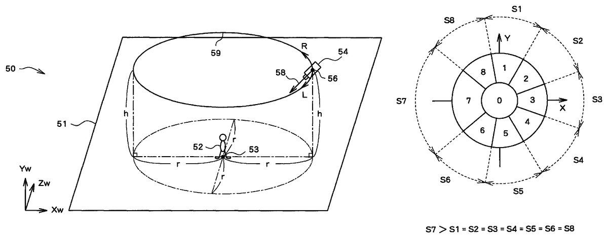
In the game machine10having the above-described hardware structure, a virtual three dimensional space (a three dimensional game space) is created in the main memory26.FIG. 3is a diagram schematically showing the three dimensional space. As shown inFIG. 3, a field object51, parallel to the Xw-Zw plane, is placed in the virtual three dimensional space50, and the player object52is placed on the field object51. The player object52is an object to be controlled by the game player, and changes the position and posture thereof according to an operation signal input from the controller32. In this embodiment, the player object52moves according to the content of the game player's operation carried out relative to the direction buttons46and/or the left operation stick40. When the game player operates the buttons44, the player object52behaves according to the content of the operation. It should be noted that although objects other than the player object52are actually placed in the virtual three dimensional space50, these objects are not shown inFIG. 3.
A virtual camera54is placed in the virtual three dimensional space50, so that a picture obtained by viewing the virtual three dimensional space50from the virtual camera54is shown on the monitor18. That is, the picture obtained by viewing from the viewpoint position56in the sight line direction vector58is shown on the monitor18. In this embodiment, the virtual camera54is placed on the camera trajectory59at the “distance (distance on the Xw-Zw plane) from the reference position53that is a predetermined distance r and the height from the field object51that is a predetermined distance h”. Here, the reference position53is determined based on the position of the player object52, which is, for example, the position of the feet of the player object52.
In this embodiment, the position and posture of the virtual camera54can be changed in response to the game player's operation carried out relative to the right operation stick42. In this embodiment, a normal operation mode and a direction designation operation mode are available as an operation mode with the virtual camera54. The direction designation operation mode is effective while the right operation stick42is kept pressed in the axial direction, and the normal operation mode is effective during other periods of time.
In the following, a normal operation mode will first be described. In the normal operation mode, in response to the right operation stick42inclined rightward or leftward, the virtual camera54(the viewpoint position56) moves along the camera trajectory59. For example, with the right operation stick42inclined rightward (the X axis positive direction inFIG. 2(a)), the virtual camera54moves along the camera trajectory59in the right direction of the virtual camera54(the R direction inFIG. 3). Also, with the right operation stick42inclined leftward (the X axis negative direction inFIG. 2(a)), the virtual camera54moves along the camera trajectory59in the left direction of the virtual camera54(the L direction inFIG. 3). In this case, the virtual camera54changes the posture (a sight line direction vector58, for example) thereof, following the change in position thereof (the viewpoint position56), such that the sight line direction vector58coincides with the direction vector extending from the viewpoint position56to a predetermined watched position (a reference position53, for example).
In the normal operation mode, with the right operation stick42inclined upward or downward, the sight line direction vector58rotates in the positive or negative direction relative of the Yw axis with the viewpoint position56as a center. For example, with the right operation stick42inclined upward (the Y axis positive direction inFIG. 2(a)), the sight line direction vector58rotates in the positive direction of the Yw axis with the viewpoint position56as a center, as shown inFIG. 4. Similarly, with the right operation stick42inclined downward (the Y axis negative direction inFIG. 2(a)), the sight line direction vector58rotates in the negative direction of the Yw axis with the viewpoint position56as a center. In this case, the sight line direction vector58is prevented from rotating in either the positive or negative direction of the Yw axis by an extent exceeding a predetermined angle.
In the following, a direction vector extending from the viewpoint position56to the reference position53is defined as a reference sight line direction vector57, and the angle between the sight line direction vector58and the reference sight line direction vector57is defined as an up/down angle θyw. For example, when the right operation stick42is inclined upward with the sight line direction vector58coincident with the reference sight line direction vector57and the sight line direction vector58is thereby rotated by ten degrees in the positive direction of the Yw axis with the viewpoint position56as a center, the up/down angle θyw “+10 degrees” results. Also, for example, when the right operation stick42is inclined downward with the sight line direction vector58coincident with the reference sight line direction vector57and the sight line direction vector58is thereby rotated by ten degrees in the negative direction of the Yw axis with the viewpoint position56as a center, the up/down angle θyw “−10 degrees” results.
In the following, a direction designation operation mode will be described. In the direction designation operation mode, the position and posture of the virtual camera54is updated such that the virtual camera54is directed in the direction corresponding to the posture data input from the right operation stick42, in the virtual three dimensional space50.
FIG. 5is a diagram showing a criterion for use in determination (a determination criterion) as to posture data input using the right operation stick42.FIG. 6is a diagram showing correspondence between the determination result about the posture data input using the right operation stick42and the direction in the virtual three dimensional space50.
As shown inFIG. 5, the posture data input from the right operation stick42is classified into nine posture states. That is, when the posture data (X, Y) is input using the right operation stick42, determination is made to find which of the areas “0” to “8” on the XY plane, shown inFIG. 5, the input data indicates. Here, the area “0” is a circular area defined on the XY plane, having a predetermined radius with the origin as the center, and corresponds to the right operation stick42in an upstanding state. The areas from “1” to “8” have the same size.
The area “1” is a 45 degree fan-like area expanding in the 0 degree direction (with the Y axial direction defined as 0 degrees, clock rotation is defined as a positive direction, which is similarly applied in the following) on the XY plane excluding the area “0”, and corresponds to the right operation stick42inclined in the 0 degree direction. The “2” area is a 45 degree fan-like area expanding in the 45 degree direction on the XY plane excluding the area “0”, and corresponds to the right operation stick42inclined in the 45 degree direction. The “3” area is a 45 degree fan-like area expanding in the 90 degree direction on the XY plane excluding the area “0”, and corresponds to the right operation stick42inclined in the 90 degree direction. The “4” area is a 45 degree fan-like area expanding in the 135 degree direction on the XY plane excluding the area “0”, and corresponds to the right operation stick42inclined in the 135 degree direction. The “5” area is a 45 degree fan-like area expanding in the 180 degree direction on the XY plane excluding the area “0”, and corresponds to the right operation stick42inclined in the 180 degree direction. The “6” area is a 45 degree fan-like area expanding in the 225 degree direction on the XY plane excluding the area “0”, and corresponds to the right operation stick42inclined in the 225 degree direction. The “7” area is a 45 degree fan-like area expanding in the 270 degree direction on the XY plane excluding the area “0”, and corresponds to the right operation stick42inclined in the 270 degree direction. The “8” area is a 45 degree fan-like area expanding in the 315 degree direction on the XY plane excluding the area “0”, and corresponds to the right operation stick42inclined in the 315 degree direction. In the following, the state in which the posture data input using the right operation stick42is located in the “n” area on the XY plane is referred to as an “n” state.
As shown inFIG. 6, the respective directions “north”, “northeast”, “east”, “southeast”, “south”, “southwest”, “west”, “northwest” in the virtual three dimensional space50are assigned to the respective areas “1” to “8”. It should be noted that, in this embodiment, the positive direction of the Zw axis is defined as “north”, and the positive direction of the Xw axis is defined as “east”.
For example, it is arranged such that in response to the game player operating the right operation stick42to incline in the 270 degree direction, the virtual camera54is set so as to be directed to the “west” (FIG. 7). That is, the viewpoint position56is changed to “a position on the camera trajectory59, ‘east’ of the reference position53”. The sight line direction vector58is changed so as to coincide with “a vector formed by rotating, with the viewpoint position56as the center, the direction vector extending from the viewpoint position56to the reference position53in the Yw axial direction by an up/down angle Oyw set in the normal operation mode”.
As described above, it is possible for the game player to instruct through a relatively easy operation in the direction designation operation mode that the virtual camera54should be directed in their desired direction.
It should be noted that in the state with the right operation stick42inclined in a certain direction, the determination criterion for the posture data input using the right operation stick42is changed. Specifically, the area corresponding to the posture state of the right operation stick42becomes larger, while the other areas become smaller.FIG. 8shows the determination criterion with the right operation stick42inclined in the 270 degree direction (the posture data input using the right operation stick42, contained in the area “7”). As shown inFIG. 8, the area “7” is larger than the other areas “1” to “6”, “8”, all having the same size. Specifically, the “7” area, corresponding to the posture state of the right operation stick42, is the fan-like area of 45+(Δθ×2) degrees expanding in the 270 degree direction on the XY plane, excluding the area “0”. The areas other than the areas “7” and “0” are fan-like areas of 45−((Δθ×2)/7) degrees excluding the area “0”. When the right operation stick42is inclined such that the posture data input using the right operation stick42indicates than area other than the areas “0” and “7” in the above, the virtual camera54is set so as to be directed in the direction corresponding to that area.
When the posture data input using the right operation stick42is changed in the vicinity of the border between the areas, the position and posture of the virtual camera54tend to change frequently, which is problematic. Such a situation can be pevented from occurring in the direction designation operation mode by the above-described arrangement.
In the direction designation operation mode, the history of the directions having been designated by the game player thus far is stored. Then, with the right operation stick42kept in the upstanding state for a predetermined period of time (T1), the virtual camera54is directed in the direction that was last designated. With the right operation stick42kept in the upstanding state for another predetermined period of time (T2), the virtual camera54is directed in the direction designated the last time but one. Thereafter, every time the right operation stick42continues to remain in the upstanding state for a predetermined period of time (T2), the virtual camera54is directed in the previously designated, by one, direction. Here, the times T1and T2may or may not be identical, though the times T1and T2are identical in the following.
As described above, in the direction designation operation mode, the virtual camera54can be directed in the direction having been designated by the game player in the past, even though the game player does not incline the right operation stick42. This can save the time and labor of the game player attempting to direct the virtual camera54in a direction previously designated.
Also, in shifting from the normal operation mode to the direction designation operation mode, information describing the viewpoint position56and the sight line direction vector58at the time of shifting is stored in the main memory26. Then, when the right operation stick42pressed in the axial direction is released, whereby the direction designation operation mode is shifted to the normal operation mode, the virtual camera54is set based on the information stored in the main memory26. In this manner, the direction designation operation mode can smoothly shift to the normal operation mode in the game machine10.
In the following, a functional structure of the game machine10will be described.FIG. 9is a functional block diagram mainly showing the functions in connection with the present invention among those realized by the game machine10. As shown, the game machine10comprises, in terms of functions, a first virtual camera control unit60, a second virtual camera control unit62, a virtual camera control switching unit64, a virtual camera state information storage unit68, and a display control unit70. These functions are realized by the microprocessor14by executing a program read from the DVD-ROM25.
[1. Virtual Camera State Information Storage Unit]
The virtual camera state information storage unit68is realized using the main memory26as a main component. The virtual camera state information storage unit68stores information describing the current position (the viewpoint position56) and posture (the sight line direction vector58) of the virtual camera54, and additionally stores information about the up/down angle θyw which is set in the normal operation mode.
[2. Virtual Camera Control Switching Unit]
The virtual camera control switching unit64is realized using the microprocessor14as a main component. The virtual camera control switching unit64switches the states, through a predetermined switching operation, between the state in which the first virtual camera control unit60controls the virtual camera54and the state in which the second virtual camera control unit62controls the virtual camera54. That is, the virtual camera control switching unit64switches the modes between the normal operation mode and the direction designation operation mode through a predetermined switching operation. The “predetermined switching operation” in this embodiment is an operation to press the right operation stick42in the axial direction, though the “predetermined switching operation” may be another operation, such as an operation to press the button34R or the like, for example.
[3. First Virtual Camera Control Unit]
The first virtual camera control unit60is realized using the microprocessor14as a main component. The first virtual camera control unit60controls the virtual camera54in the normal operation mode. The first virtual camera control unit60determines the change direction in which the posture of the virtual camera54is changed, based on the state of operation of the controller32, and changes the posture of the virtual camera54to the target posture in which the virtual camera52is directed in the direction displaced by a predetermined angle in that change direction relative to the current direction. In this embodiment, the first virtual camera control unit60determines the change direction in which the posture of the virtual camera54is changed, based on the state of operation of the right operation stick42.
It should be noted that the first virtual camera control unit60stores, when the virtual camera control switching unit64switches state from the state in which the first virtual camera control unit60controls the virtual camera54(the normal operation mode) to the state in which the second virtual camera control unit62controls the virtual camera54(the direction designation operation mode), the information (the posture specification information) specifying the viewpoint position56and the sight line direction vector58at that time in the main memory26. Meanwhile, when the virtual camera control switching unit64switches the state from the state in which the second virtual camera control unit62controls the virtual camera54(the direction designation operation mode) to the state in which the first virtual camera control unit60controls the virtual camera54(the normal operation mode), the first virtual camera control unit60sets the viewpoint position56and the sight line direction vector58based on the information stored in the main memory26.
[4. Second Virtual Camera Control Unit]
The second virtual camera control unit62is realized using the microprocessor14as a main component. The second virtual camera control unit62controls the virtual camera54in the direction designation operation mode. The second virtual camera control unit62determines a direction in the virtual three dimensional space50based on the state of operation of the controller32, and changes the posture of the virtual camera54to a target posture in which the virtual camera54is directed in that direction. In this embodiment, the first virtual camera control unit60determines the direction in the virtual three dimensional space50based on the state of operation of the right operation stick42.
The second virtual camera control unit62stores determination criterion data describing the determination criterion of the posture data input from the right operation stick42. In this embodiment, determination criterion data (base determination criterion data) describing the determination criterion, such as is shown inFIG. 5, is stored. Also, for each of the areas “1” to “8”, determination criterion data in the case where the posture data input from the right operation stick42is contained in that area is stored. That is, the determination criterion data describing the determination criterion, such as is shown inFIG. 8, for example, is stored in each area “1” to “8”.
When the posture data input from the right operation stick42is contained in the area “0”, the second virtual camera control unit62obtains the direction corresponding to that posture data in the virtual three dimensional space50based on the base determination criterion data. Meanwhile, when the posture data input from the right operation stick42is contained in any of the areas “1” to “8”, the second virtual camera control unit62obtains the direction corresponding to that posture data in the virtual three dimensional space50based on the determination criterion data corresponding to that area. Then, the second virtual camera control unit62changes the posture of the virtual camera54such that the virtual camera54is directed in the obtained direction.
It should be noted that it may be arranged such that the second virtual camera control unit62stores only the above-described base determination criterion data, and the determination criterion data corresponding to the respective areas “1” to “8” may be produced based on the above-described base determination criterion data.
[5. Direction History-Related Information Storage Unit]
The second virtual camera control unit62includes a direction history-related information storage unit66. The direction history-related information storage unit66is realized using the main memory26as a main component. The direction history-related information storage unit66stores direction history-related information concerning the history of “the direction in the virtual three dimensional space50, in which the virtual camera54is arranged to be directed by the second virtual camera control unit62”.
In this embodiment, for example, direction history data (alignment data), such as is shown inFIG. 10, for example, is stored. The direction history data contains data about the directions having been designated the past N number of times by the game player by inclining the right operation stick42in the direction designation operation mode. It should be noted that the direction history data contains data about the directions having been designated by the game player, arranged in order beginning with the last designated one.
In response to a predetermined operation, the second virtual camera control unit62changes the posture of the virtual camera54to a target posture in which the virtual camera52is directed in the direction determined based on the direction history data in the virtual three dimensional space50.
[6. Display Control Unit]
The display control unit70is realized using the microprocessor14and the image processing unit16as main components. The display control unit70sets the virtual camera54based on the content stored in the virtual camera state information storage unit68, and displays on the monitor18a game screen image showing the picture obtained by viewing the virtual three dimensional space50from the virtual camera54. In other words, the display control unit70displays on the monitor18a game screen image showing “a picture obtained by viewing the virtual three dimensional space50from the viewpoint position56stored in the virtual camera state information storage unit68in the direction indicated by the sight line direction vector58stored in the virtual camera state information storage unit68”.
In the following, a process to be carried out in the game machine10for every predetermined period of time ( 1/60 second in this embodiment) will be described.FIGS. 11 to 14show flowcharts of a process according to the present invention among those carried out by the game machine10every predetermined period of time. The process shown in these drawings is realized by the microprocessor14by executing a program stored in the DVD-ROM25.
As shown inFIG. 11, the virtual camera control switching unit64determines whether or not the right operation stick42is pressed in the axial direction (S101). That is, whether or not an operational signal indicative of a pressing operation carried out relative to the right operation stick42is input from the controller32is determined. When it is determined that the right operation stick42is pressed in the axial direction, the process (S102to S121) in the direction designation operation mode is carried out. Meanwhile, when it is determined that the right operation stick42is not pressed in the axial direction, the process (S122to S127, S115) in the normal operation mode is carried out.
With the right operation stick42pressed, whether or not the operation mode flag indicates “0” is determined (S102). The operation mode flag is information describing whether the current operation mode of the virtual camera54is a normal operation mode or a direction designation operation mode, and stored in the main memory26. The operation mode flag indicates either “0” or “1”, with “0” for the normal operation mode and “1” for the direction designation operation mode.
With the right operation stick42pressed and the operation mode flag indicating “0”, which concerns the state immediately after the right operation stick42is pressed, the process to initialize the direction designation operation mode (S103to S106) is carried out.
That is, the variables t and i are initialized to “0” (S103). The variable t is used to measure the period of time with the right operation stick42kept upstanding in the direction designation operation mode (see116and S117). The variable i is a numeric value serving as a base in reading the direction from the direction history data (seeFIG. 10) at S119to be described later.
Thereafter, the current area ID is initialized to “0” (S104) The current area ID is an area ID of the area corresponding to the inclination state of the current right operation stick42, and stored in the main memory26. The current area ID takes any of the values “0” to “8” (seeFIGS. 5 and 8).
Then, the viewpoint position56and the sight line direction vector58(the position and posture of the virtual camera54) at that time are read from the virtual camera state information storage unit68, and stored in the main memory26as a viewpoint position56and a sight line direction vector58for use in resuming the normal mode (S105). In addition, the operation mode flag is updated to “1” (S106).
With the process to initialize the direction designation operation mode completed (S103to S106), or in response to the determination that the operation mode flag takes a value other than “0” (N at S102), the second virtual camera control unit62determines whether or not the right operation stick42is in the upstanding state (S107). That is, whether or not the posture state of the right operation stick42is the “0” state is determined.
When it is determined that the right operation stick42is not in the upstanding state, the second virtual camera control unit62initializes the variables t and i into “0” (S108).
Then, the second virtual camera control unit62obtains determination criterion data corresponding to the current area ID (S109). For example, with the current area ID being “0”, determination criterion data describing the determination criterion, such as is shown inFIG. 5, is obtained. Also, when the current area ID being “7”, for example, determination criterion data describing the determination criterion, such as is shown inFIG. 8, is obtained.
Thereafter, the second virtual camera control unit62obtains the area ID corresponding to the inclination state of the right operation stick42based on the determination criterion data obtained at S109(S110). That is, the second virtual camera control unit62determines to which of the states “1” to “8” the inclination state of the right operation stick42belongs, based on the posture data of the right operation stick42, output from the controller32.
Then, when the area ID obtained at S110is different from the current area ID (Y at S111), the second virtual camera control unit62changes the current area ID stored in the main memory26to the area ID obtained at S110(S112). Also, the second virtual camera control unit62obtains the direction corresponding to the area ID obtained at S110based on the data shown inFIG. 6, and additionally registers in the direction history data (seeFIG. 10) (S113). It should be noted that the second virtual camera control unit62first erases the direction having been recorded earliest, when the N number of directions is already contained in the direction history data, and thereafter additionally registers the direction obtained at S110.
Thereafter, the second virtual camera control unit62updates the viewpoint position56and the sight line direction vector58(the position and posture of the virtual camera54) such that the virtual camera54is directed in the direction corresponding to the current area ID (S114). Initially, the second virtual camera control unit62calculates the viewpoint position56. Specifically, the second virtual camera control unit62calculates, as the viewpoint position56, a position on the camera trajectory59in “a direction opposite from the direction corresponding to the current area ID” relative to the reference position53. Thereafter, the second virtual camera control unit62calculates the sight line direction vector58. Specifically, the second virtual camera control unit62calculates a direction vector (the reference sight line direction vector57) extending from the calculated viewpoint position56to the reference position53. Further, the second virtual camera control unit62reads the up/down angle Oyw from the virtual camera state information storage unit68, calculates a vector, as a sight line direction vector58, obtained by rotating the reference sight line direction vector57in the Yw axial direction by the up/down adjustment angle θy with the viewpoint position56calculated as described above as a center, and updates the viewpoint position56and the sight line direction vector58, stored in the virtual camera state information storage unit68, to the viewpoint position56and the sight line direction vector58calculated as described above.
It should be noted that, when it is determined that the right operation stick42is in the upstanding state (Y at S107), the second virtual camera control unit62increments the variable t (S116). Then, when the variable t is equal to or larger than T (Y at S117), the second virtual camera control unit62increments the variable i (S118), and obtains the i-th direction among the N number of directions contained in the direction history data (S119). Then, the second virtual camera control unit62updates the viewpoint position56and the sight line direction vector58(the position and posture of the virtual camera54) such that the virtual camera54is directed in the direction obtained at S119(S120). The process at this step is carried out similarly to the process at S114. Thereafter, the variable t is initialized to “0” (S121).
Also, when it is determined that the right operation stick42is not pressed in the axial direction (N at S101), whether or not the operation mode flag indicates “1” is determined (S122). With the right operation stick42not pressed in the axial direction and the operation mode flag indicating “1”, which concerns the state immediately after the pressed right operation stick42is released, the process to initialize the normal operation mode (S123to S125) is carried out.
That is, the first virtual camera control unit60obtains, from the main memory26, the viewpoint position56and the sight line direction vector58(see105) which are stored as the viewpoint position56and the sight line direction vector58for use in resuming the normal operation mode when shifting from the normal operation mode to the direction designation operation (S123). Then, the first virtual camera control unit60updates the viewpoint position56and the sight line direction vector58, stored in the virtual camera state information storage unit68, to the viewpoint position56and the sight line direction vector58obtained at S123(S124). Thereafter, the operation mode flag is updated to “0” (S125).
Meanwhile, when the operation mode flag does not indicate “1” (N at S122), the first virtual camera control unit60obtains the inclination state of the right operation stick42based on the posture data of the right operation stick42, output from the controller32(S126). Then, the first virtual camera control unit60updates the viewpoint position56and the sight line direction vector58(the position and posture of the virtual camera54) based on the inclination state of the right operation stick42(S127).
For example, when the right operation stick42is inclined rightward (the X axis positive direction inFIG. 2(a)), the first virtual camera control unit60reads the current viewpoint position56from the virtual camera state information storage unit68. Then, the first virtual camera control unit60calculates as a new viewpoint position56“a position on the camera trajectory59, having moved from the current viewpoint position56in the virtual camera54's right direction by a predetermined distance (a movement distance of the virtual camera54for every 1/60 seconds)”. Thereafter, the first virtual camera control unit60calculates the sight line direction vector58in the new viewpoint position56. Initially, the first virtual camera control unit60calculates a direction vector (the reference sight line direction vector57) extending from the new viewpoint position56to the reference position53. Then, the first virtual camera control unit60reads the up/down angle θyw stored in the virtual camera state information storage unit68, and calculates, as a new sight line direction vector58, a vector formed by rotating the reference sight line direction vector57in the Yw axial direction by the up/down angle θyw with the new viewpoint position56as a center. The first virtual camera control unit60updates the viewpoint position56and the sight line direction vector58, stored in the virtual camera state information storage unit68, to the viewpoint position56and the sight line direction vector58calculated as described above. It should be noted that a similar process is carried out when the right operation stick42is included leftward (the X axis negative direction inFIG. 2(a)).
Also, when the right operation stick42is inclined upward (the Y axis positive direction inFIG. 2(a)), for example, the first virtual camera control unit60reads the current up/down angle θyw of the virtual camera54from the virtual camera state information storage unit68, and updates the up/down angle θyw stored in the virtual camera state information storage unit68to the θyw+Δθyw. Further, the first virtual camera control unit60reads the current viewpoint position56and sight line direction vector58of the virtual camera54from the virtual camera state information storage unit68, and calculates, as a new sight line direction vector58, a vector formed by rotating the current sight line direction vector58in the Yw axial direction by the up/down angle Δθyw with the viewpoint position56as a center. Then, the first virtual camera control unit60updates the sight line direction vector58, stored in the virtual camera state information storage unit68, to the newly calculated sight line direction vector58. It should be noted that Δθyw indicates a predetermined increase/decrease angle for every 1/60 second. A similar process is carried out also when the right operation stick42is inclined downward (the Y axis negative direction inFIG. 2(a)).
The display control unit70reads the viewpoint position56and the sight line direction vector58from the virtual camera state information storage unit68, and renders a game screen image showing a picture obtained by viewing the virtual three dimensional space50from the viewpoint position56in the direction indicated by the sight line direction vector58, in the VRAM (S115). The game screen image rendered in the VRAM is displayed on the monitor18at a predetermined timing.
As described above, according to the game machine10, the game player, who loses the idea about their desired direction in the virtual three dimensional space50or the like, can direct the virtual camera54in their desired direction by inclining the right operation stick42in the direction corresponding to the desired direction. That is, the game player can direct the virtual camera54in their desired direction in the virtual three dimensional space50through a relatively simple operation.
It should be noted that the present invention is not limited to the above-described embodiment.
For example, the direction history data (seeFIG. 10) may contain the current up/down angle θyw at that time together with the direction. Then, in the process at S119and S120, the second virtual camera control unit62obtains the up/down angle θyw together with the direction, and updates the viewpoint position56and the sight line direction vector58based thereon.
Also, for example, it may be arranged such that, in the direction designation operation mode, the virtual camera54is directed in the direction determined based on the direction history data as the most frequently designated by the game player, when the right operation stick42remains in the upstanding state for a predetermined period of time. Also, when the right operation stick42remains in the upstanding state for another predetermined period of time, the virtual camera54may be directed in the direction determined based on the direction history data as second most frequently designated by the game player. As described above, every time the right operation stick42continues to remain in the upstanding state for a predetermined period of time, the virtual camera54is sequentially directed in different directions, beginning with the direction determined, based on the direction history data, as that most frequently designated by the game player.
Also, for example, the direction history-related information stored in the direction history-related information storage unit66may include a direction and a total period of time with the virtual camera54remaining directed in that direction in the direction designation operation mode. Then, when the right operation stick42remains in the upstanding state for a predetermined period of time in the direction designation operation mode, the virtual camera54may be directed in the direction related to the longest total period of time. Also, when the right operation stick42continues, from that state, to remain in the upstanding state for another predetermined period of time, the virtual camera54may be directed in the direction related to the second longest total period of time. As described above, every time the right operation stick42continues to remain in the upstanding state for a predetermined period of time, the virtual camera54may be sequentially directed in different directions, beginning with the direction related to the longest total period of time.
The present invention can be applied, for example, to a so-called first person viewpoint game.
Although it is described in the above that a program is supplied from a DVD-ROM25, or an information storage medium, to the consumer game machine11, the program may alternatively be distributed via a network program to home or the like.FIG. 15is a diagram showing a whole structure of a program distribution system using a communication network. A program distribution method according to the present invention will be described with reference toFIG. 15. As shown inFIG. 15, the program distribution system100comprises a game database102, a server104, a communication network106, a personal computer108, a consumer game machine110, and a PDA (a personal digital assistance)112. The game database102and the server104together constitute a program distribution device114. The communication network106comprises, for example, the Internet and/or a cable television network. In this system, the game database102(an information storage medium) stores a program identical to the content recorded in the DVD-ROM25. Then, when the user requests distribution of the game, using the personal computer108, the consumer game machine110, the PDA112, or the like, the request is transmitted via the communication network106to the server104. Then, the server104, in response to the game distribution request, reads a program from the game database102, and sends to the entity, such as the personal computer108, the consumer game machine110, the PDA112, or the like, having made the game distribution request. Here, although it is described in the above that game distribution is carried out in response to a game distribution request, the server104may send a game unidirectionally. Also, it is not necessary for all programs necessary to realize the game to be distributed all at once (collective distribution), and only game components necessary according to a particular aspect of the game may be distributed (divided distribution). As described above, game distribution via the communication network106makes it possible for the user wishing to obtain a program to readily obtain the program.
Claims
- A game machine for showing a picture obtained by viewing a virtual three dimensional space from a virtual camera placed in the virtual three dimensional space, the game machine comprising: a processor and a memory, first virtual camera control means for determining by the processor a change direction in which a posture of the virtual camera is changed, based on a state of operation of operation means, and changing the posture of the virtual camera such that the virtual camera is directed in a direction displaced from a current direction in the change direction by a predetermined angle;second virtual camera control means for determining by the processor a direction in the virtual three dimensional space based on the state of operation of the operation means, and changing the posture of the virtual camera such that the virtual camera is directed in the determined direction;virtual camera control switching means for, by the processor, switching states, according to a predetermined switching operation, between a state in which the first virtual camera control means controls the virtual camera and a state in which the second virtual camera control means controls the virtual camera;and operation value acquisition means for acquiring, by the processor, an operation value in accordance with the state of operation of the operation means, wherein the second virtual camera control means includes means for acquiring content stored in means for storing any of a plurality of directions in the virtual three dimensional space so as to correspond to a respective range of the plurality of operation value ranges which do not overlap;and determination means for determining whether or not the operation value acquired by the operation value acquisition means is contained in any of the plurality of operation value ranges, and changes the posture of the virtual camera, when it is determined that the operation value acquired by the operation value acquisition means is contained in any of the plurality of operation value ranges, such that the virtual camera is directed in a direction corresponding to that operation value range, and the determination means changes the plurality of operation value ranges, when it is determined that the operation value acquired by the operation value acquisition means is contained in any of the plurality of operation value ranges, such that that operation value range is expanded and other operation value ranges are narrowed, and determines whether or not the operation value acquired by the operation value acquisition means is contained in any of the plurality of operation value ranges, based on the plurality of operation value ranges after change.
- The game machine according to claim 1 , wherein the first virtual camera control means includes means for storing posture specification information in storage means when the virtual camera control switching means switches the state in which the first virtual camera control means controls the virtual camera to the state in which the second virtual camera control means controls the virtual camera, the posture specification information specifying the posture of the virtual camera at that time;and means for setting the posture of the virtual camera based on the posture specification information stored in the storage means when the virtual camera control switching means switches the state in which the second virtual camera control means controls the virtual camera to the state in which the first virtual camera control means controls the virtual camera.
- The game machine according to claim 1 , wherein the second virtual camera control means includes means for storing the direction history-related information comprising a history of directions in which the virtual camera has been set by the second virtual camera control means;and means for determining, based on a previously designated direction the direction history-related information, the direction in the virtual three dimensional space, in response to the predetermined operation, and changing the posture of the virtual camera such that the virtual camera is directed in that direction.
- The game machine according to claim 1 , wherein the first virtual camera control means determines a change direction in which a posture of the virtual camera is changed, based on an inclination direction of an operation stick included in the operation means, and changes the posture of the virtual camera such that the virtual camera is directed in a direction displaced from a current direction in the change direction by a predetermined angle, the second virtual camera control means determines a direction in the virtual three dimensional space based on the inclination direction of the operation stick, and changes the posture of the virtual camera such that the virtual camera is directed in the determined direction, and the predetermined switching operation is an operation to press the operation stick in an axial direction.
- A control method of a game machine for showing a picture obtained by viewing a virtual three dimensional space from a virtual camera placed in the virtual three dimensional space, comprising: a first virtual camera control step of determining by a processor a change direction in which a posture of the virtual camera is changed, based on a state of operation of operation means, and changing the posture of the virtual camera such that the virtual camera is directed in a direction displaced from a current direction in the change direction by a predetermined angle;a second virtual camera control step of determining by the processor a direction in the virtual three dimensional space based on the state of operation of the operation means, and changing the posture of the virtual camera such that the virtual camera is directed in the determined direction;a virtual camera control switching step of switching states by the processor, according to a predetermined switching operation, between a state in which the virtual camera is controlled at the first virtual camera control step and a state in which the virtual camera is controlled at the second virtual camera control step;and an operation value acquisition step for acquiring, by the processor, an operation value in accordance with the state of operation of the operation means, wherein the second virtual camera control step includes a step of acquiring content stored in means for storing any of a plurality of directions in the virtual three dimensional space so as to correspond to a respective range of the plurality of operation value ranges which do not overlap;and a step of determining whether or not the operation value acquired by the operation value acquisition step is contained in any of the plurality of operation value ranges, and changes the posture of the virtual camera, when it is determined that the operation value acquired by the operation value acquisition step is contained in any of the plurality of operation value ranges, such that the virtual camera is directed in a direction corresponding to that operation value range, and the step of determining changes the plurality of operation value ranges, when it is determined that the operation value acquired by the operation value acquisition is contained in any of the plurality of operation value ranges, such that that operation value range is expanded and other operation value ranges are narrowed, and determines whether or not the operation value acquired by the operation value acquisition step is contained in any of the plurality of operation value ranges, based on the plurality of operation value ranges after change.
- A non-transitory computer readable information storage medium storing a program for causing a computer to function as a game machine for showing a picture obtained by viewing a virtual three dimensional space from a virtual camera placed in the virtual three dimensional space, the computer functioning as: first virtual camera control means for determining a change direction in which a posture of the virtual camera is changed, based on a state of operation of operation means, and changing the posture of the virtual camera such that the virtual camera is directed in a direction displaced from a current direction in the change direction by a predetermined angle;second virtual camera control means for determining a direction in the virtual three dimensional space based on the state of operation of the operation means, and changing the posture of the virtual camera such that the virtual camera is directed in the determined direction;virtual camera control switching means for switching states, according to a predetermined switching operation, between a state in which the first virtual camera control means controls the virtual camera and a state in which the second virtual camera control means controls the virtual camera;and operation value acquisition means for acquiring, by the processor, an operation value in accordance with the state of operation of the operation means, wherein the second virtual camera control means includes means for acquiring content stored in means for storing any of a plurality of directions in the virtual three dimensional space so as to correspond to a respective range of the plurality of operation value ranges which do not overlap;and determination means for determining whether or not the operation value acquired by the operation value acquisition means is contained in any of the plurality of operation value ranges, and changes the posture of the virtual camera, when it is determined that the operation value acquired by the operation value acquisition means is contained in any of the plurality of operation value ranges, such that the virtual camera is directed in a direction corresponding to that operation value range, and the determination means changes the plurality of operation value ranges, when it is determined that the operation value acquired by the operation value acquisition means is contained in any of the plurality of operation value ranges, such that that operation value range is expanded and other operation value ranges are narrowed, and determines whether or not the operation value acquired by the operation value acquisition means is contained in any of the plurality of operation value ranges, based on the plurality of operation value ranges after change.
- A game machine for showing a picture obtained by viewing a virtual three dimensional space from a virtual camera placed in the virtual three dimensional space, the game machine comprising: a processor and a memory, first virtual camera control means for determining by the processor a change direction in which a posture of the virtual camera is changed, based on a state of operation of operation means, and changing the posture of the virtual camera such that the virtual camera is directed in a direction displaced from a current direction in the change direction by a predetermined angle;second virtual camera control means for determining by the processor a direction in the virtual three dimensional space based on the state of operation of the operation means, and changing the posture of the virtual camera such that the virtual camera is directed in the determined direction;virtual camera control switching means for, by the processor, switching states, according to a predetermined switching operation, between a state in which the first virtual camera control means controls the virtual camera and a state in which the second virtual camera control means controls the virtual camera;operation value acquisition means for acquiring, by the processor, an operation value in accordance with the state of operation of the operation means;and means for determining, by the processor, based on direction history-related information, a direction to which the virtual camera is set to direct most frequently or for the longest total period of time by the second virtual camera control means, in response to a predetermined operation, and changing the posture of the virtual camera such that the virtual camera is directed in the determined direction, wherein the direction history-related information comprises a history of directions in which the virtual camera has been set by the second virtual camera control means.
- A control method of a game machine for showing a picture obtained by viewing a virtual three dimensional space from a virtual camera placed in the virtual three dimensional space, comprising: a first virtual camera control step of determining by a processor a change direction in which a posture of the virtual camera is changed, based on a state of operation of operation means, and changing the posture of the virtual camera such that the virtual camera is directed in a direction displaced from a current direction in the change direction by a predetermined angle;a second virtual camera control step of determining by the processor a direction in the virtual three dimensional space based on the state of operation of the operation means, and changing the posture of the virtual camera such that the virtual camera is directed in the determined direction;a virtual camera control switching step of switching by the processor states, according to a predetermined switching operation, between a state in which the virtual camera is controlled at the first virtual camera control step and a state in which the virtual camera is controlled at the second virtual camera control step;an operation value acquisition step for acquiring, by the processor, an operation value in accordance with the state of operation of the operation means;and a step of determining by the processor, based on direction history-related information, a direction to which the virtual camera is set to direct most frequently or for the longest total period of time by the second virtual camera control step, in response to a predetermined operation, and changing the posture of the virtual camera such that the virtual camera is directed in the determined direction, wherein the direction history-related information comprises a history of directions in which the virtual camera has been set by the second virtual camera control step.
- A non-transitory computer readable information storage medium storing a program for causing a computer to function as a game machine for showing a picture obtained by viewing a virtual three dimensional space from a virtual camera placed in the virtual three dimensional space, the computer functioning as: first virtual camera control means for determining a change direction in which a posture of the virtual camera is changed, based on a state of operation of operation means, and changing the posture of the virtual camera such that the virtual camera is directed in a direction displaced from a current direction in the change direction by a predetermined angle;second virtual camera control means for determining a direction in the virtual three dimensional space based on the state of operation of the operation means, and changing the posture of the virtual camera such that the virtual camera is directed in the determined direction virtual camera control switching means for switching states, according to a predetermined switching operation, between a state in which the first virtual camera control means controls the virtual camera and a state in which the second virtual camera control means controls the virtual camera;operation value acquisition means for acquiring, by the processor, an operation value in accordance with the state of operation of the operation means;and means for determining, based on direction history-related information, a direction to which the virtual camera is set to direct most frequently or for the longest total period of time by the second virtual camera control means, in response to a predetermined operation, and changing the posture of the virtual camera such that the virtual camera is directed in the determined direction, wherein the direction history-related information comprises a history of directions in which the virtual camera has been set by the second virtual camera control means.
Disclaimer: Data collected from the USPTO and may be malformed, incomplete, and/or otherwise inaccurate.