U.S. Pat. No. 8,228,336
INTEGRATING A MOTION SYNTHESIS SYSTEM INTO A VIDEO GAME SYSTEM
AssigneeLucasfilm Entertainment Company Ltd.
Issue DateMarch 17, 2011
Illustrative Figure
Abstract
The present disclosure includes, among other things, systems, methods and program products for integrating a motion synthesis system into a video game system.
Description
Like reference numbers and designations in the various drawings indicate like elements. DETAILED DESCRIPTION FIGS. 1A-1Care screenshots showing example procedural animations100,120, and140, respectively. In general, a procedural animation can be used to generate motion data for a character or object represented in a game. Motion data can include, but is not limited to, one or more transformations that provide a description of the motion for one or more parts of a character or an object. For example, one or more translation matrices, one or more rotational matrices, or any combination thereof can be used to provide transformations that are used as a description of motion. In various implementations, the motion data describes the motions of one or more of the character's bones. For example, as illustrated inFIG. 1A, character102is represented by a simple skeleton that is procedurally animated (e.g., in procedural animation100) to extend its arms in anticipation of striking the ground. Within this document, we define the term “simple skeleton” to mean a skeleton that contains fewer bones than a more complex skeletal structure. For example, consider character102. Each arm is made up of only three bones: an upper arm bone104a, a forearm bone104b, and a hand bone104c. A more complex skeletal structure (e.g., a full skeleton, described in reference toFIGS. 2 and 4) may include an upper arm bone, two bones in the forearm (e.g., corresponding to the ulna and radius), and many bones in the hand (e.g., corresponding to one or more bones in any or all of the carpals, metacarpals, and phalanges) or some other skeletal configuration that includes more bones than the simple skeleton, for example. In some implementations, the number of bones is related to the amount of joint expression that is used. For example, if a character does not usually open or close ...
Like reference numbers and designations in the various drawings indicate like elements.
DETAILED DESCRIPTION
FIGS. 1A-1Care screenshots showing example procedural animations100,120, and140, respectively. In general, a procedural animation can be used to generate motion data for a character or object represented in a game. Motion data can include, but is not limited to, one or more transformations that provide a description of the motion for one or more parts of a character or an object. For example, one or more translation matrices, one or more rotational matrices, or any combination thereof can be used to provide transformations that are used as a description of motion. In various implementations, the motion data describes the motions of one or more of the character's bones. For example, as illustrated inFIG. 1A, character102is represented by a simple skeleton that is procedurally animated (e.g., in procedural animation100) to extend its arms in anticipation of striking the ground.
Within this document, we define the term “simple skeleton” to mean a skeleton that contains fewer bones than a more complex skeletal structure. For example, consider character102. Each arm is made up of only three bones: an upper arm bone104a, a forearm bone104b, and a hand bone104c. A more complex skeletal structure (e.g., a full skeleton, described in reference toFIGS. 2 and 4) may include an upper arm bone, two bones in the forearm (e.g., corresponding to the ulna and radius), and many bones in the hand (e.g., corresponding to one or more bones in any or all of the carpals, metacarpals, and phalanges) or some other skeletal configuration that includes more bones than the simple skeleton, for example. In some implementations, the number of bones is related to the amount of joint expression that is used.
For example, if a character does not usually open or close their hand (e.g., because they are typically carrying an object), then a more complex skeletal structure for the hand may not be necessary. Within this document, we define the term “joint expression” to mean a capacity to manipulate a character or object using an inter-skeletal joint. For example, opening and closing a hand with multiple bones may express numerous joints. As another example, because the character102is defined with only a few arm bones, the character102can only express joints between upper arm bone104aand forearm bone104b, and forearm bone104band hand bone104c. Full skeletons are described in more detail in reference toFIG. 2.
In reference toFIG. 1B, as the character102strikes the ground, a new procedural animation120is generated to produce a description of motion that corresponds to the in-game character catching themselves. For example, the positions of the arm bones104a,104b, and104chave been modified to represent an arm that is bent to break the fall of the character102. In addition, certain constraints can also be enforced to ensure that the character102is moving in an intelligent, human-like manner. For example, as the character hits the ground, each bone is acted upon by a set of physical forces. One or more constraints can be enforced to ensure that the hand bone104cremains connected to the forearm bone104band the forearm bone104bremains connected to the upper arm bone104a, to name a few examples.
In reference toFIG. 1C, once the character102is on the ground, a new procedural animation140can be generated to produce a description of motion that corresponding to the in-game character rolling over; possibly as a precursor to a procedural animation where the in-game character rises to their feet. As show in procedural animation140, bones104a,104b, and104cmove in a manner congruent with the act of rolling over. In addition, because the constraints are still enforced, the force of the movement does not displace the connectivity between the bones104a,104b, and104cbeyond a certain tolerance (e.g., as described by the constraints).
FIG. 2is a block diagram showing an example video game system200. In general, the video game system200can use some or all of a procedurally generated animation for a simplified skeleton and generate additional joint expressions for a more complicated skeleton. In various implementations, the simplified skeleton is used by a motion synthesis system that generates procedural animations for the simplified skeleton. Once the procedural animation has been generated, the video game system200can use the procedural animations generated for the simplified skeleton in combination with additional animations (e.g., both procedural and non-procedural animations) to provide animations for the more complicated skeleton.
As illustrated byFIG. 2, the game system200includes a game engine202, a motion synthesis system204, a macro behavior system206, and a physics engine208. In general, the game engine202includes instructions, that when executed, receive user input, process the user input, modify in-game objects, and display the results of the received user input, to name a few example. In other words, the game engine202generates the game's virtual world and allows the user to interact with objects in the virtual world. In various implementations, the game engine202accesses one or more stored representations of objects in the virtual world and renders them on a display device. For example, the game engine202can access a character with full skeleton210b, and generate an in-game representation through a variety of rendering techniques. Rendering techniques include, but are not limited to, rasterization, ray casting, and ray tracing, to name a few examples. In addition, the game engine202includes an artificial intelligence (AI) module203. In general, the AI module203is responsible for controlling characters or objects that are either partially controlled, or not controlled by the user using, for instance, deterministic or non-deterministic techniques such as pattern movement, flocking, potential function-based movement, finite state machines, fuzzy logic, rule-based AI, Bayesian techniques, neural networks, and genetic algorithms. For example, in a squad-based game, the user may provide commands to certain other squad members, but the AI module203may execute those commands or alter those commands based on the current state of the virtual world.
If the user wants to move a character in the virtual world, the user can specify an in-game action through a user input device (e.g., a mouse, keyboard, game pad, other input device, or any combination thereof). The game engine202can translate these received inputs into one or more motion behaviors. Motion behaviors include, but are not limited to, standing, sitting, running, falling, and jumping, to name a few examples. In addition, the game engine202can generate motion behaviors corresponding to actions generated by an AI module203. In various implementations, motion behaviors generated by the AI module203are applied to computer-controlled characters. For example, the AI module can determine that a computer-controlled character should run after the player controlled character and generate one or more appropriate motion behaviors.
The game engine202can provide the one or more selected motion behaviors to the macro behavior system206. In general, the macro behavior system206can map motion behaviors from the game engine202to motion behaviors for the motion synthesis system204, and can modify one or more parameters of the mapped motion behaviors that are then provided to motion synthesis system204. For example, in response to user input, the game engine202can generate motion behavior210and provide it to macro behavior system206. In response, macro behavior system206can generate one or more motion behaviors212a-212nthat are provided to motion synthesis system204. In some implementations, the motion behavior210and any of212a-212nare substantially similar. In other implementations, the motion behavior210and any of212a-212nare different. For example, motion behavior210may describe a jumping motion behavior, while212a-212nmay describe motion behaviors associated with the character bending their knees, extending their legs, swinging their arms, bracing for impact, or other motion descriptions. In various implementations, the motion synthesis system204can provide a motion description214to the macro behavior system206. In general, the motion description214can be used by the macro behavior system206to generate a second description of motion216, described in more detail below. The motion description216can be used by the game engine202to animate full skeleton210b. The macro behavior system206is described in more detail in reference toFIG. 5.
The motion synthesis system204receives the one or more motion behaviors and applies them to a simplified skeleton. For example, motion synthesis system204can apply any or all of the received motion behaviors212a-212nto simplified skeleton210a. In various implementations, the simplified skeleton is a simplified representation of a skeleton used on an in-game character. For example, simplified skeleton210ais a representation of full skeleton210b. In other words, in reference toFIGS. 1A-1C, character102can be represented by simple skeleton210ain the motion synthesis system204and by full skeleton210bin the game engine202.
In various implementations, during the generation of the procedural animations, the motion synthesis system204can use physics engine208to provide additional information that may be used to generate the description of motion. For example, the motion system204can provide attributes of the character through an application programming interface (API). In response, the physics engine208can determine trajectory and/or the position of the in-game character that is procedurally animated, to name two examples. In general, the physics engine208exerts one or more physical forces (e.g., gravity, friction, acceleration, and combinations thereof) on the character or object. For example, in reference toFIG. 1A, gravity can be exerted on the character102to determine a rate of descent as an animation for the character102is procedurally generated to extend the character's arms to brace for impact. The determined trajectory and/or position of the in-game character can be used to modify the one or more portions of the procedurally generated animations generated by motion synthesis system204.
For example, the transformations that describe one or more portions of the procedurally generated animation can be altered by the addition of motion imparted by the physical forces that are applied by the physics engine208to the character. In various implementations, the modified descriptions may be provided to the motion synthesis system204to procedurally generate motion descriptions that are used by the game engine202to animate the in-game characters. An example physics engine208is Havok Physics available from Havok (San Francisco, Calif.). In some scenarios, the physics engine208may modify the descriptions of motion to such an extent that the modified descriptions are inconsistent with an intelligent, human-like motion. For example, the physics engine208may exert a large enough force to generate a motion where one or more of the character's limbs interpenetrates a wall, a table, or another in-game object, to name a few examples. In general, this interpenetration can cause the motion synthesis system204to generate a description of motion that is not similar to human-like motion. For example, the character may become stuck or move in an otherwise counter intuitive manner. Interpenetration is described in more detail in reference toFIGS. 6A-6BandFIG. 7.
The game engine202can use the motion description216provided by macro behavior system206to animate the full skeleton210b. In various implementations, the game engine202or the macro behavior system206determines a mapping between the full skeleton210band the simple skeleton210a. In cases where the bones in the full skeleton210bmap to a corresponding bone in the simple skeleton, the motion description for the corresponding bone in the full skeleton210bis the motion description for the bone in the simple skeleton210a. For example, consider a leg in the simple skeleton210athat includes an upper leg bone, a lower leg bone, and a foot bone, and a leg in the full skeleton210bthat includes an upper leg bone (e.g., the femur), a knee cap bone (e.g., a patella bone), two lower leg bones (e.g., the tibia and fibula), and one or more bones of foot (e.g., metatarsals, phalanges, talus, or other bones in the foot). If the simple skeleton210ais procedurally animated with a walking behavior, because the upper leg bone of the full skeleton210bcorresponds to the upper leg bone of the simple skeleton210a, the game engine can apply a same or similar motion description to the upper leg bone of the full skeleton210b.
In cases where a full skeleton210bbone does not correspond to a simple skeleton210abone, the game engine202can determine a simulated description of motion for the bone. For example, the game engine202can identify motion data in a predefined animation script, keyframe data, or other motion description and apply it to the full skeleton210bbone. As another example, the game engine202can use the physics engine208to determine a procedural animation for the full skeleton210bbone. As another example, a description of motion for one or more nearby bones in the simple skeleton210acan be combined and applied to a bone in the full skeleton210b. In some scenarios, a combination of the approaches can be used. For example, keyframe data can be combined with procedurally generated motion from the physics engine208to generate a simulated description of motion for the full skeleton210b.
FIG. 3is a flow chart of an example technique300for generating a description of motion for a full skeleton (e.g., full skeleton210b). In general, the technique300can be used by the system200to generate one or more animations for the full skeleton210b. In various implementations, the technique can be executed in response to user input or in response to a system200request. For example, game engine202may request an execution of technique300after a predetermined amount of time has elapsed (e.g., 1/60thof a second). In general, technique300can be executed to generate the animation information for each image frame of a video game. In various implementations, game engine202can generate image frames on the order of a certain number of frames per second. For example, the game engine202may generate at least thirty frames per second. In general, the number of frames per second can depend on the parameters specified by the game engine202, the rendering hardware, the graphics settings, other parameters, or computing resources used by other aspects of system200, to name a few examples. These additional considerations may reduce the number of frames generated below thirty frames per second.
In step302, system200identifies a character defined by both a simple skeleton and a full skeleton. For example, a character defined by simple skeleton210aand a full skeleton210bcan be identified by system200. In general, the skeletons210aand210bcan be stored in memory, on a compact disk (CD), a digital versatile disk (DVD), or other storage medium. In some scenarios, the character can be obtained by identifying a character corresponding to received user input and the corresponding skeletal information obtained. For example, a player controlled character can be identified and their simple and full skeletal representations obtained when a user moves their respective in-game character. As another example, the character can be obtained when the user's character attacks another computer-controlled character. In other words, the computer-controlled character is identified as the target of the attack and the computer-controlled character's skeletal representations are obtained. In other scenarios, the character can be obtained by identifying a character corresponding to a game related event. For example, game engine202can identify a computer-controlled character through an AI event performed by AI module203. For example, if the AI module203moves a computer controlled character towards a player controlled character the game engine202can identify the computer-controlled character from the AI event, and obtain their respective skeletal representations. As another example, if the AI module203instructs a controlled character to attack the player controlled character, the game engine202can identify the computer controlled character, the player controller character, or both and obtain skeletal representations for the computer controlled character, the player controlled character, or both.
In step304, a first motion behavior to be applied to the character is identified. In some scenarios, the first motion behavior can be specified by the received user input. For example, if the user input specifies a running action, a running motion behavior to be applied to the character is identified. In other scenarios, the first motion behavior can be specified by the game engine202. For example, a first motion behavior to be applied to a computer-controlled character can be identified corresponding to an action specified by the AI module203.
In step306, the first motion behavior is converted to one or more second motion behaviors. In general, the first motion behavior can be modified by one or more additional parameters. A motion behavior specifies motion characteristics for one or more skeleton bones in a character or an object. Such characteristics can include, but are not limited to, a path of travel through a volume, resistance, velocity, acceleration, and momentum at various points in time. For example, the first motion behavior corresponding to the speed of motion can be modified by the macro behavior system206. As another example, parameters corresponding to 3-dimensional coordinates (e.g., X, Y, and Z coordinates) can be modified by the macro behavior system206to specify a range of motion, general direction, or other parameters of the motion behavior. In some scenarios, additional motion behaviors can be generated corresponding to the first motion behavior. For example, if a character is falling, a motion behavior corresponding to the character's head turning or arms flailing can also be generated by the macro behavior system206.
In step308, the one or more second motion behaviors are provided to a motion synthesis system. In general, the motion synthesis system receives the one or more second motion behaviors and generates a description of motion. For example, motion synthesis system204can receive second motion behaviors212a-212nand generate one or more motion descriptions for simple skeleton210a. In general, parameters included in the motion behaviors can be used by the motion synthesis system to procedurally generate realistic, human-like motion. For example, parameters can control the speed of motion for a particular character limb. In addition, the motion synthesis system can generate a general description for the motion based on the forces applied to that particular limb. The combination of the parameters with the general description of motion can yield a description of motion that is applied to the simple skeleton210a. In some scenarios, the description of motion provided by the motion synthesis system is modified by other influences. For example, physics engine208can modify the descriptions of motion generated by motion synthesis system204to corresponding to a trajectory of the character or a position where the character lands, to name two examples.
In step310, a description of motion for the simplified skeleton is received. For example, the physics engine208can provide the description of motion to the game engine202. In response, the system200attempts to generate a description of motion for the full skeleton210b. For example, for each bone of the full skeleton210b, the system200may do any or all of the following:
In step312, the system200can map the bones from the full skeleton210bto the simple skeleton210a. In some implementations, the system can determine a mapping by comparing the coordinates and/or names associated with a specific bone in a skeleton. For example, consider a bone with end points of (X1, Y1, Z1) and (X2, Y2, Z2) with the name “femur bone” in the simple skeleton210a, and a bone with end points of (X1, Y1, Z1) to (X2, Y2, Z2) with the name “femur bone” in the full skeleton210b. Because the coordinate ranges are same, the system200may determine that there is a correspondence between the two bones. The system200may also compare the bone names to aid in the determination of correspondence. For example, because both bones share the name “femur bone,” the correspondence is reinforced.
If there is a correspondence, in step314, the motion description of the corresponding bone is assigned to the full skeleton bone. For example, a description of motion for the “femur bone” in simple skeleton210ais assigned to the “femur bone” of the full skeleton210b.
If there is not a correspondence, in step316, the system200determines if there is a predefined animation script or a technique for generating procedural animations that can be used to provide a description of motion. For example, the system200can access keyframe data associated with the character to determine if there is a predefined animation script that can be used to provide a description of motion for the full skeleton bone. As another example, in some scenarios, the physics engine208can be used to provide one or more procedural animations for the full skeleton bone.
If there is a predefined script or a mechanism for generating procedural animations, in step318, the system200assigns a description of motion based on the script or procedure to the full skeleton bone.
If there is not a predefined animation script or procedure that can provide a description of motion then, in step320, the system200combines the descriptions of motion of one or more nearby bones. For example, in a full skeleton with an upper leg bone, a kneecap bone, and two lower leg bones, the system200may combine the motion of the upper leg, and the two lower leg bones to generate a description of motion for the kneecap bone.
In step322, the system200assigns the combined description of motion to the full skeleton bone. For example, in some implementations, the system200can interpolate between two motions and assign the interpolated description of motion to the full skeleton bone.
In step324, the in-game character representation is animated corresponding to the description of motion assigned to one or more of the character's bones. For example, the system200can generate one or more frames of animation corresponding to the description of motion assigned to one or more of the character's bones. The one or more frames of animations can be generated using tradition animation techniques.
FIGS. 4A and 4Bare example limbs400and420for a simple skeleton and a full skeleton, respectively. The limb400includes three bones, an upper leg bone402, a lower leg bone404, and a foot bone404. The limb420includes an upper leg bone422, a kneecap bone424, two lower leg bones,426and428, a heel bone430, and additional bones in the foot432a-432nand434a-434n.
As described in reference toFIG. 3, when the motion synthesis system204generates a description of motion, the system200attempts to determine a correspondence between each bone in limb420and a bone in limb400. For example because the system200can map bone422to402(e.g., because they are in substantially similar locations and/or with substantially similar physical dimensions), the system200can determine a correspondence between the two bones. This correspondence can be used to determine some or all of a particular description of motion to apply to a bone. For example, because bone422corresponds to bone402, the description of motion for bone402can be used to describe the motion for bone422.
For other bones, such as bones424,426,428,430,432a-432n, and434a-434nthe system200may not be able to determine a correspondence. Descriptions of motion can be generated for these bones in various ways. For example, because bones426and428express joints collectively, and not individually (e.g., if a joint is expressed using bone426, bone428also is involved in the joint expression, and visa versa), a description of motion can be simulated for bone428using the description of motion for bone426. As another example, in other scenarios, the description of motion can be generated by combining the description of motion of nearby bones. For example, the motion description for bone424may be determined by combining the motions of bones404and402to generate a new description of motion for bone424. As another example, the description of motion may be determined by animation script and/or a procedurally generated animation for one or more of the bones. For example, motion for bones432a-432nand/or bones434a-434ncan be described by an animation script, where the animation can be displayed (e.g., grafted, overlaid, or otherwise rendered) using the orientation of foot bone406that is specified by the description of motion for bone406.
In some scenarios, an animation script and/or a procedurally generated animation may also modify the description of motion for one or more bones. For example, the motion descriptions for some or all of the bones in limb420can be modified by using physics engine208to determine one or more physical effects that are exerted on the bones in limb420. As another example, keyframe data can be used to modify the motion data for one or more bones after an initial motion description has been determined.
FIG. 5is a block diagram showing an example macro behavior system206. In general, one or more commands can be received by the macro behavior system206using a first API. For example, in reference toFIG. 2, the game engine202can provide first motion behaviors to macro behavior system206though the first API. In addition, the macro behavior system206can provide instructions to other subsystems of system200using a second API. For example, in reference toFIG. 2, the macro behavior system206can provide second motion behaviors to motion synthesis system204using a second API.
In various implementations, the macro behavior system206can be used to override certain parameters used by the motion synthesis system204when generating one or more descriptions of motion. In various implementations, the parameters are modified by the incorporation of one or more files or through the execution of code during runtime operation. In addition, the macro behavior system206can be configured to override certain character assets or game characters. For example, a player-controlled character may walk in a different manner than a computer-controlled character. This allows the macro behavior system206to be used to configure different intelligent, human-like, descriptions of motion for different classes of in-game characters, for example. Moreover, the macro behavior system206is provided with a capacity to randomize one or more parameters to provide subtle and not-so-subtle differences in the like motions generated by the motion synthesis system204. For example, a random staggering speed can be determined to generate two different descriptions of motion for a substantially similar staggering motion behavior. In various implementations, the macro behavior system206can be configured with one or more Extensible Markup Language (XML) files corresponding to a behavior asset definition file502, and one or more macro behavior files (e.g.,504a-504n).
In general, the asset definition file502specifies a skeleton to motion synthesis body part mapping as well as one or more macro behavior files504a-504nto load, to name two examples. An example of an asset definition file502is illustrated in TABLE 1:
TABLE 1......
The first portion of asset definition file502describes the skeletal mapping (e.g., between a simple skeleton and a full skeleton, respectively). For example, the skeletal volume named “Pelvis” is mapped to the bone specified by the data structure “Hips[0]”. The second portion of asset definition file502describes the one or more macro behavior files to load. For example, the example asset definition shown in Table 1 specifies at least three macro behavior files including “Assets/Euphoria/MaleBehaviors Jump.xml.”
Each macro behavior file includes on or more macro behaviors (e.g.,514a-514n). In addition, each macro behavior includes one or more motion behaviors (e.g., Euphoria behaviors524a-524n). Each motion behavior also includes one or more parameters534a-534n. An example macro behavior file is illustrated in TABLE 2 below:
TABLE 2
A macro behavior is defined using one or more values including, name, initialBufferedVelocityMultiplier, continuousBufferedData, drivesPosition, and drivesRotation, to name a few examples. The name value specifies the name by which the particular macro behavior is reference via the execution of code, processing a script, or in any other manner. The initialBufferedVelocityMultiplier value specifies a multiplier that use used to scale the one or more velocities calculated from animation data that is passed to the motion synthesis system204. For example, an initialBufferedVelocityMultiplier of 1.0 specifies that the initial velocity value is not scaled (i.e., multiplied by a scalar of 1). As another example, an initialBufferedVelocityMultiplier of 0.0 specifies that the initial velocity value is not used (i.e., multiplied by a scalar of 0). The continuousBufferedData value specifies whether or not any of the motion synthesis system204behaviors require continuous feeding of the animation transforms. In various implementations, these values are only passed in when a character is coming from a completely animated state (e.g., from an animation script) and transitioning into a behavior-driven state (e.g., a procedurally animated state), or vice-versa. The drivesPosition value indicates if the position of the character should be derived from the physical positions of the simulated body in the motion synthesis system204. For example, if drivesPosition is false, the motion synthesis system204will not substantially alter the character position generated from the simulation. The drivesRotation value indicates if the rotation/facing of the character should be derived from the physical orientation of the simulated body in the motion synthesis system204. For example, if drivesRotation is false, the motion synthesis system204will not substantially alter the character orientation generated from the simulation.
In further implementations, each macro behavior includes one or more motion behaviors. Each of the motion behaviors can be defined using one or more values including name and startStop, to name two examples. The name value specifies the name of the motion behavior that the particular macro behavior references. In various implementations, the name value is defined by the behavior asset definition file502and must be substantially similar to a name specified by the motion synthesis system204. In some scenarios, more than one motion behavior can be associated with a macro behavior. For example, a macro behavior that causes a character to their balance may cause the character to stumble and wing their arms in a manner consistent with someone attempting to regain their balance. The startStop value indicates whether or not this motion synthesis behavior supports start/stop functionality (e.g., whether the motion synthesis behavior can be stopped and/or started before a particular motion ceases). In various implementations, the proper setting for this is indicated by the motion synthesis system204. For example, the proper setting may be indicated by the presence of the “start” parameter documentation describing the motion synthesis system204.
In addition, each motion behavior can be configured with one or more parameters. Each parameter can be specified by one or more attributes including name, type, value and override, for instance. The name attribute specifies the name of the motion behavior parameter. In various implementations, the name attribute must be the same or similar to the name expected by the motion synthesis system204The type attribute specifies the parameter type. Types can include, for instance, int, float, bool, and char, to name a few examples. The int type is an integer value parameter. The float type is a floating-point value parameter. The bool type is a Boolean value parameter. The char type is a string value parameter.
Each type can also have an associated value defined, as specified by the value attribute. In general, the value attribute specifies a default value to use for the particular parameter if not otherwise overridden. For all type attributes it is possible to specify a single value. For the int, float and bool types it is also possible to specify a range of values that the macro behavior system206randomly selects within. The format for an example attribute value range is “low_value to high_value” (e.g., “0.3 to 10.0” or “5 to 7”).
The override attribute specifies the override parameter slot to assign this parameter. In various implementations, the override attribute is a string indicating both an override type as well as a numeric slot for that type, in the format type_slot. Override strings include, “VectorX—0,” “Int—3,” and “BodyPart—7,” to name a few examples. In various implementations, the macro behavior system206can process numerous override types including, VectorX, VectorY, VectorZ, Float, Int, Char, BodyPart, PhysicsEntity, DynamicFloat, DynamicInt, DynamicBool, DynamicChar, and DynamicVector, to name some examples.
By way of illustration, if a macro behavior has three float parameters, there would be three different parameter slots to hold those values. One parameter would be assigned to slot Float—0, the next to slot Float—1, and the last to slot Float—2, so that each can each have unique values passed in. Conversely, if it was specified that Float—0 was to be used for all of the parameters, the parameters would all receive the same value that was placed into the Float—0 override parameter.
The VectorX, VectorY, and VectorZ override types specifies that the x, y, or z components, respectively, of the override vector in the defined slot will be used as the value for the particular parameter. The Float, Int, and Char override types specifies that the float, int, or string value, respectively, in the defined slot will be used as the value for the particular parameter. The BodyPart override type specifies the appropriate integer index of the body part associated with a crc32 name in the defined slot will be used as the value for this parameter. In various implementations, the crc32 name is translated by the system into an integer body index for use by the motion synthesis system204during runtime operation. The PhysicsEntity override type specifies that the physics entity (e.g., a pointer data type associated with a physics entity data structure) in this override slot will be used as the value for the particular parameter. In various implementations, the PhysicsEntity is translated by the system200into a pointer data type associated with a rigid body used by the physics engine208for use by the motion synthesis system204during runtime operation. The DynamicFloat, DynamicInt, DynamicBool, DynamicChar, and DynamicVector override types specify that the float, int, Boolean, string value, or vector value, respectively, corresponding to a pointer data type in the defined override slot will be used as a dynamic parameter in the motion synthesis system204. In general, the system200performs the necessary translation and runtime hookups to provide the functionality that allows for changes to the original value passed in to automatically affect the motion synthesis system204during runtime operation without sending additional messages.
A macro behavior can be executed in a variety of ways. For example, the game engine202can execute one or more macro behaviors through code506, that when executed, provides the motion behavior system206the name of the macro behavior as well as providing any override data that the executed code specifies. As another example, animation events508(e.g., animation events generated by specific keyframes) can trigger one or more macro behaviors. In general, it is possible to layer macro behaviors by starting one after the other. For example, a staggering macro behavior can be started and then a macro behavior corresponding to an arms flailing motion can be started to generate a motion behavior that when provided to the motion synthesis system204generates a description of motion for a character that is staggering with arms flailing.
FIGS. 6A and 6Bare screenshots600and620, respectively, of an in-game representation with interpenetration. The screenshots600and620are not to scale and are used for illustrative purposes. In general, interpenetration occurs when one or more portions of a character penetrate or otherwise interact with the subsurface geometry of another object. For example, character102has a portion of their respective skeletal structure (e.g., arm bones104a,104b, and104c) interpenetrating a wall602. In various implementations, interpenetration occurs with a large force is applied to one or more portions of a character. In some scenarios, the force applied is large enough to push a portion of one object into the subsurface geometry of another object. For example, character602may have been knocked off their feet with such force that a portion of their arm, represented by bones104a-104c, becomes lodged in a portion of the wall602.
In general, if the representations illustrated byFIGS. 6A and 6Bare provided to motion synthesis system204, some or all of the procedurally generated animations for character102may not resemble human-like motions. For example, the character may not move because doing so would violate one or more constraints. As another example, because the character may be able to move a small amount before the constraints are violated, the constraints may cause the character to move in a lurching, non-fluid manner. In other words, because a portion of the character may become stuck in or attached to the interpenetrated object, this can reduce the human-like qualities of the procedurally generated animations.
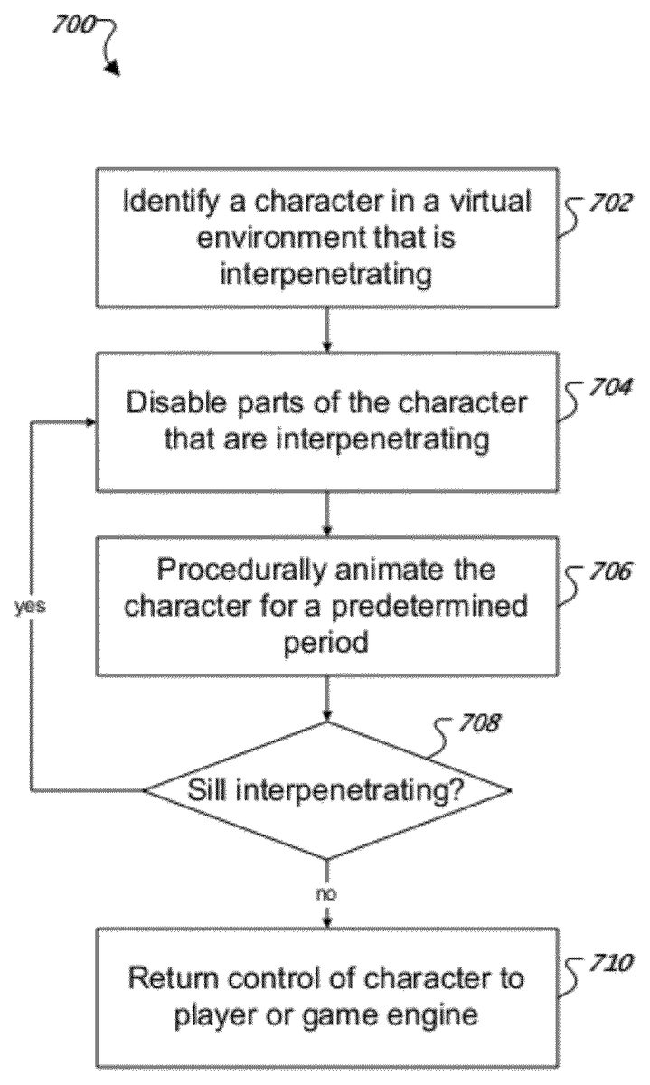
FIG. 7is a flow diagram of an example technique700for correcting procedural animations where one or more portions of a character are interpenetrating. In general, technique700can be executed by system200during generation of one or more procedural animations. For example, technique700can be executed by system200when the physics engine208modifies one or more motion descriptions.
In step702, a character in a virtual environment that is interpenetrating is identified. In general, one or more collisions can be detected using a hierarchical tree structure. For example, consider a character's skeleton where the central portion (e.g., the torso) is the root node of the tree and one or more extremity portions (e.g., the limbs) are leaf nodes of the tree. The positions of the nodes can be compared to positions of other objects in the virtual environment. For example, the positions of the limbs can be compared to the position of a wall in the virtual environment. In some implementations, comparing the positions of the nodes can be accomplished by first determining if any of the constraints have been violated. If one or more constraints have been violated, then a ray can be cast from the portion of the skeleton that violate the constraints to another portion of the skeleton that violate the constraints to determine if there is an object between them. For example, if the ray touches an object between the two skeletal portions, then there is another object between the portions.
In step704, parts of the character that are interpenetrating are disabled. In general, one or more aspects of a character's animation state can be modified. For example, the collisions for the one or more portions of the character are disabled. As another example, the constraints for the one or more portions of the character that are interpenetrating are disabled. In various implementations, the disabling of the constraints and/or the disabling of the collisions is determined based on the hierarchical tree structure. For example, nodes that are furthest from the root node are disabled before the nodes that are closer to the root node.
In step706, the character is procedurally animated for a predetermined period. For example, the system200can perform technique300to generate one or more frames of animation. In general, the frames of animation generated by technique300correspond to the disabled collisions and/or the disabled constraints. For example, if one or more constraints are disabled, the portions of the skeletal structure that are interpenetrating may move farther apart for a certain number of frames before moving closer together.
In step708, the system200determines if portions of the skeletal structure are still interpenetrating. In some implementations, one or more one or portions of step702may be used to determine if portions of the skeletal structure are still interpenetrating. For example, violated constraints can be identified and rays cast between portions that violate the constraints to determine if there is an object between the two portions of the skeletal structure that violate the constraints. If there are additional portions of the skeletal structure that are still interpenetrating, then system200may execute step704. In various implementations, additional portions of the skeletal structure are determined corresponding to their respective positions in the hierarchical tree structure. In other words, the next portions that are farthest from the root node are disabled. In various implementations, the process of repeatedly disabling the next portions that are farthest from the root node is performed until the portions of the skeletal structure are not interpenetrating other objects.
In step710, control of the character is returned to the player or game engine. In general, the system200may return the character's animation state to some previous value or set of values. For example, the system200can re-enable the collision detection for the previously disabled nodes. As another example, the system200can re-enable to the constraints for the previously disabled nodes.
FIG. 8is a schematic diagram of an example of a generic computer system800. The system800can be used for the operations described in association with the method300according to one implementation. For example, the system800may be included in computer game system200.
The system800includes a processor810, a memory820, a storage device830, and an input/output device840. Each of the components810,820,830, and840are interconnected using a system bus850. The processor810is capable of processing instructions for execution within the system800. In one implementation, the processor810is a single-threaded processor. In another implementation, the processor810is a multi-threaded processor. The processor810is capable of processing instructions stored in the memory820or on the storage device830to display graphical information for a user interface on the input/output device840.
The memory820stores information within the system800. In one implementation, the memory820is a computer-readable medium. In one implementation, the memory820is a volatile memory unit. In another implementation, the memory820is a non-volatile memory unit.
The storage device830is capable of providing mass storage for the system800. In one implementation, the storage device830is a computer-readable medium. In various different implementations, the storage device830may be a floppy disk device, a hard disk device, an optical disk device, or a tape device.
The input/output device840provides input/output operations for the system800. In one implementation, the input/output device840includes a keyboard and/or pointing device. In another implementation, the input/output device840includes a display unit for displaying graphical user interfaces.
The features described can be implemented in digital electronic circuitry, or in computer hardware, firmware, software, or in combinations of them. The apparatus can be implemented in a computer program product tangibly embodied in an information carrier, e.g., in a machine-readable storage device or in a propagated signal, for execution by a programmable processor; and method steps can be performed by a programmable processor executing a program of instructions to perform functions of the described implementations by operating on input data and generating output. The described features can be implemented advantageously in one or more computer programs that are executable on a programmable system including at least one programmable processor coupled to receive data and instructions from, and to transmit data and instructions to, a data storage system, at least one input device, and at least one output device. A computer program is a set of instructions that can be used, directly or indirectly, in a computer to perform a certain activity or bring about a certain result. A computer program can be written in any form of programming language, including compiled or interpreted languages, and it can be deployed in any form, including as a stand-alone program or as a module, component, subroutine, or other unit suitable for use in a computing environment.
Suitable processors for the execution of a program of instructions include, by way of example, both general and special purpose microprocessors, and the sole processor or one of multiple processors of any kind of computer. Generally, a processor will receive instructions and data from a read-only memory or a random access memory or both. The essential elements of a computer are a processor for executing instructions and one or more memories for storing instructions and data. Generally, a computer will also include, or be operatively coupled to communicate with, one or more mass storage devices for storing data files; such devices include magnetic disks, such as internal hard disks and removable disks; magneto-optical disks; and optical disks. Storage devices suitable for tangibly embodying computer program instructions and data include all forms of non-volatile memory, including by way of example semiconductor memory devices, such as EPROM, EEPROM, and flash memory devices; magnetic disks such as internal hard disks and removable disks; magneto-optical disks; and CD-ROM and DVD-ROM disks. The processor and the memory can be supplemented by, or incorporated in, ASICs (application-specific integrated circuits).
To provide for interaction with a user, the features can be implemented on a computer having a display device such as a CRT (cathode ray tube) or LCD (liquid crystal display) monitor for displaying information to the user and a keyboard and a pointing device such as a mouse or a trackball by which the user can provide input to the computer.
The features can be implemented in a computer system that includes a back-end component, such as a data server, or that includes a middleware component, such as an application server or an Internet server, or that includes a front-end component, such as a client computer having a graphical user interface or an Internet browser, or any combination of them. The components of the system can be connected by any form or medium of digital data communication such as a communication network. Examples of communication networks include, e.g., a LAN, a WAN, and the computers and networks forming the Internet.
Thus, particular embodiments of the invention have been described. Other embodiments are within the scope of the following claims. For example, the actions recited in the claims can be performed in a different order and still achieve desirable results.
Claims
- A computer-implemented method comprising: identifying a computer-generated character comprising one or more parts that are interpenetrating in a real-time game environment, where the computer-generated character is represented by a hierarchical tree structure of parts and a root of the tree is a central part and leaves of the tree are extremity parts, where said identifying the computer-generated character comprising the one or more parts that are interpenetrating in the real-time game environment comprises: detecting two parts of the computer-generated character that are separated by a distance that exceeds a constraint threshold;and raycasting between the two parts and determining whether an object is between them;disabling from collisions the parts of the computer-generated character that are interpenetrating and the parts further from the root of the tree than the interpenetrating parts in the hierarchical tree structure;procedurally animating the computer-generated character using a motion synthesis system and a physics engine for a pre-determined amount of simulated time;and re-enabling collisions of the disabled parts.
- The method of claim 1 , further comprising: determining whether the identified parts are still interpenetrating after said procedurally animating the computer-generated character for the pre-determined amount of simulated time;and performing said re-enabling the collisions of the disabled parts based on a result of the determination.
- The method of claim 2 , further comprising: in response to determining that the identified parts are still interpenetrating, disabling from collisions other parts of the computer-generated character that are farther from the root of the tree than the previously disabled parts;and repeating said procedurally animating the computer-generated character using the motion synthesis system and the physics engine for the pre-determined amount of simulated time.
- The method of claim 2 , further comprising performing said re-enabling the collisions of the disabled parts in response to determining that the identified parts are not interpenetrating.
- A program product encoded on a non-transitory computer-readable medium, the program product including instructions that, when executed by data processing apparatus, cause the data processing apparatus to perform operations comprising: identifying a computer-generated character comprising one or more parts that are interpenetrating in a real-time game environment, where the computer-generated character is represented by a hierarchical tree structure of parts and a root of the tree is a central part and leaves of the tree are extremity parts, where the operation of identifying the computer-generated character comprising the one or more parts that are interpenetrating in the real-time game environment comprises: detecting two parts of the computer-generated character that are separated by a distance that exceeds a constraint threshold;and raycasting between the two parts and determining whether an object is between them;disabling from collisions the parts of the computer-generated character that are interpenetrating and the parts further from the root of the tree than the interpenetrating parts in the hierarchical tree structure;procedurally animating the computer-generated character using a motion synthesis system and a physics engine for a pre-determined amount of simulated time;and re-enabling collisions of the disabled parts.
- The program product of claim 5 , wherein the operations further comprise: determining whether the identified parts are still interpenetrating after said procedurally animating the computer-generated character for the pre-determined amount of simulated time;and performing the operation of re-enabling the collisions of the disabled parts based on a result of the determination.
- The program product of claim 6 , wherein the operations further comprise: in response to determining that the identified parts are still interpenetrating, disabling from collisions other parts of the computer-generated character that are farther from the root of the tree than the previously disabled parts;and repeating the operation of procedurally animating the computer-generated character using the motion synthesis system and the physics engine for the pre-determined amount of simulated time.
- The program product of claim 6 , wherein the operations further comprise performing the operation of re-enabling the collisions of the disabled parts in response to determining that the identified parts are not interpenetrating.
- A system comprising: a display device;machine-readable storage device including a program product;and one or more processors operable to execute the program product, interact with the display device, and perform operations comprising: identifying a computer-generated character comprising one or more parts that are interpenetrating in a real-time game environment, where the character is represented by a hierarchical tree structure of parts and the root of the tree is a central part and the leaves of the tree are extremity parts, where the operation of identifying the computer-generated character comprising the one or more parts that are interpenetrating in the real-time game environment comprises: detecting two parts of the computer-generated character that are separated by a distance that exceeds a constraint threshold;and raycasting between the two parts and determining whether an object is between them;disabling from collisions the parts of the computer-generated character that are interpenetrating and the parts further from the root of the tree than the interpenetrating parts in the hierarchical tree structure;procedurally animating the computer-generated character using a motion synthesis system and a physics engine for a pre-determined amount of simulated time and re-enabling collisions of the disabled parts.
- The system of claim 9 , wherein the operations further comprise: determining whether the identified parts are still interpenetrating after said procedurally animating the computer-generated character for the pre-determined amount of simulated time;and performing the operation of re-enabling the collisions of the disabled parts based on a result of the determination.
- The system of claim 10 , wherein the operations further comprise: in response to determining that the identified parts are still interpenetrating, disabling from collisions other parts of the computer-generated character that are farther from the root of the tree than the previously disabled parts;and repeating the operation of procedurally animating the computer-generated character using the motion synthesis system and the physics engine for the pre-determined amount of simulated time.
- The system of claim 10 , wherein the operations further comprise performing the operation of re-enabling the collisions of the disabled parts in response to determining that the identified parts are not interpenetrating.
Disclaimer: Data collected from the USPTO and may be malformed, incomplete, and/or otherwise inaccurate.