U.S. Pat. No. 8,210,534
INFLATABLE VEHICLES FOR SIMULATING DRIVING FOR USE WITH VIDEO GAMES
AssigneeCTA Digital, Inc.
Issue DateOctober 25, 2011
Illustrative Figure
Abstract
An inflatable vehicle for simulating a driving experience while playing realistic computer-video driving games such as the WII games. The vehicle is life-like in construction and allows a player to sit therein while playing driving game. A steering wheel or handle bar is configured to receive a game controller—which controls the video game when the steering wheel or handle bar is manipulated like a real life equivalent thereof.
Description
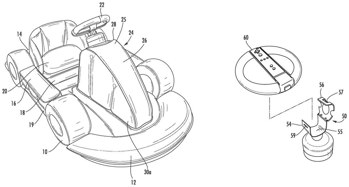
DETAILED DESCRIPTION OF THE INVENTION Embodiments of the present invention will now be described with reference to the above-identified figures. However, the drawings and the description herein of the invention are not intended to limit the scope of the invention. It will be understood that various modifications of the present description of the invention are possible without departing from the spirit of the invention. Also, features or steps described herein may be omitted, additional steps or features may be included, and/or features or steps described herein may be combined in a manner different from the specific combinations recited herein without departing from the spirit of the invention, all as understood by those of skill in the art. FIG. 1shows an inflatable race car that is fashioned to resemble a real-life car having wheels10, a front bumper12, a rear bumper14, doors16, a dashboard28and a steering wheel22. The interior of the car has a floor surface18and a seat20, which is positioned near the rear end of car. An underlying chassis19supports the structural elements of the car. Toward the front end of the car, there is a front body structure24, which arises from floor surface18. The front body structure24serves as a front body of the vehicle and as a steering wheel attachment structure. Front body is an elevated structure24having a first end (base) rising from the floor surface18and a second end forming a gradual peak25. Two sidewalls30a,30bdescend from peak25toward each side of the car and are each flanked at their base by an exposed floor surface. Another two walls slope frontward and rearward. A frontward wall26descends from peak25facing the exterior of the car (“exterior wall”) and a rearward wall28faces the interior of the car (“interior wall”). The exterior wall26is designed to look like the front hood of a race car—having a gradual downward ...
DETAILED DESCRIPTION OF THE INVENTION
Embodiments of the present invention will now be described with reference to the above-identified figures. However, the drawings and the description herein of the invention are not intended to limit the scope of the invention. It will be understood that various modifications of the present description of the invention are possible without departing from the spirit of the invention. Also, features or steps described herein may be omitted, additional steps or features may be included, and/or features or steps described herein may be combined in a manner different from the specific combinations recited herein without departing from the spirit of the invention, all as understood by those of skill in the art.
FIG. 1shows an inflatable race car that is fashioned to resemble a real-life car having wheels10, a front bumper12, a rear bumper14, doors16, a dashboard28and a steering wheel22. The interior of the car has a floor surface18and a seat20, which is positioned near the rear end of car. An underlying chassis19supports the structural elements of the car.
Toward the front end of the car, there is a front body structure24, which arises from floor surface18. The front body structure24serves as a front body of the vehicle and as a steering wheel attachment structure. Front body is an elevated structure24having a first end (base) rising from the floor surface18and a second end forming a gradual peak25. Two sidewalls30a,30bdescend from peak25toward each side of the car and are each flanked at their base by an exposed floor surface. Another two walls slope frontward and rearward. A frontward wall26descends from peak25facing the exterior of the car (“exterior wall”) and a rearward wall28faces the interior of the car (“interior wall”). The exterior wall26is designed to look like the front hood of a race car—having a gradual downward slope. The interior wall is a dashboard28and it serves as a location for mounting the steering wheel22. Dashboard28, is provided with an attachment mechanism for pivotably attaching a steering wheel22.
The various structural elements, such as, for example, the chassis19, wheels10, seat20and front body24each comprise a respective-shaped structures made of PVC or such similar material. The respective structures take shape when they are fully inflated with air. It will be understood that some of the structures may be independently formed and require to be separately inflated, whereas, other structures may be in fluid communication with each other such that air is shared between two or more structures.
As shown inFIG. 2, during play, a player sits on seat20resting his/her feet on the floor and naturally grasps the steering wheel22in the same manner as one would when driving a real-life vehicle. The motion of the steering wheel is sensed in the WII game by line of sight communication between the controller held in the steering wheel22and a console located in the proximity of a screen33. The motion of the steering wheel is, thus, sensed as real life motion to control images displayed on a display device. There are other motion sensitive driving games which can sense movement of a specific game controller and such games can advantageously use this invention.
In a preferred embodiment of the invention, the car is designed to accommodate both adults and children alike. For example, to best accommodate players of wide ranging heights, the ear is designed with an elongated foot resting area31(best shown in FIG.7)—for receiving a player's foot in any location along the elongated area31. In a preferred embodiment, foot resting area31is an exposed floor surface18on either side of front body structure24. A player sitting on seat20places his/her feet in foot resting area31. The legs of an adult or tall player may extend entirely into foot resting area31(as shown inFIG. 2), whereas the legs of a child might extend only partway into foot resting area31. In addition, the car design also allows for a child to sit directly on the floor18in front of seat20to better reach steering wheel22.
The distance between seat20and front body structure24is preferably from about 200 mm to 250 mm. This distance was found by the inventor to best accommodate the fullest range of player heights. The width of seat20is from about 330 min to 400 mm.
Furthermore, steering wheel22may be adjusted (e.g. between the two positions depicted inFIG. 6) to tailor steering wheel accessibility to players of various heights. A short player, for example, will move the steering inward (toward him/herself) for ease of reach, whereas a taller player might tilt the steering outward (away from him/herself).
In addition to adjustability, the steering wheel is securely mounted such that it is able to withstand forces exerted by an adult playing the WII game. To that end, the various components that comprise the steering wheel attachment and locking mechanism (described in more detail below) is reinforced and designed to be of high integrity.
In order to support adults, a thick PVC (or a material similar thereto) material is used. In a preferred embodiment, the PVC is double the thickness of inflatable pool toys.
FIGS. 3A and 3Bshow a steering wheel attachment mechanism according to an embodiment of the invention. As shown, a base member40is securely attached to the dashboard28of front structure24. Preferably, a permanent glue is utilized to attach base member40. Most preferably the permanent glue is of a kind that possess elastic qualities after being fully dried. Base40is adapted to receive a wheel attachment mechanism for attaching a steering wheel. For example, in a preferred embodiment, a collar42attached to base40is sized and shaped to be inserted into a complementary tubular steering column cap44. Steering column cap44is designed to be tightly secured to collar42. To that end, in a preferred embodiment of the invention, collar42comprises one or more attachment tabs130(best seen inFIG. 4A) helping to ensure a secure connection between the steering column and base40or body of the kart. This will be described in more detail below with reference toFIGS. 4 and 5.
As an added security measure and to ensure proper alignment, in an embodiment of the invention, tab46is vertically slidably connected to column cap44, which moves into a corresponding slot48in collar42. Tab46slides upward and downward (i.e. toward and away from the collar as oriented inFIG. 3a)—but not laterally. To secure the steering wheel, a user inserts the cap44into collar42and rotates it until the parts are assembled and locked together as will be described below.
It will be understood by those of ordinary skill in the art that the parts of the steering column may be connected by any of various engagement means—all of which are within the scope of the invention. For example, column cap44may be held within collar42by way of a tight frictional engagement, detent mechanism, threaded engagement or any similar locking mechanism. In addition, the steering wheel and steering column cap could be permanently mounted to the inflatable vehicle or made unitary therewith. Still further, in another embodiment of the invention—a steering column cap is not required. Rather, a steering wheel could be mounted by a pivot directly onto a base provided on the vehicle—obviating the need for a steering column cap.
Each of the engagement means requires that the securement between the steering column cap and body be such that it is sufficiently strong that even an adult excited during the playing of the WII game can not physically separate the steering wheel from the body of the inflatable kart.
FIG. 3Bshows a perspective view of the steering column cap44. As shown, a rotating head49couples a steering wheel cradle50to the steering wheel column44. In a preferred embodiment, head49extends from a cylindrical shaft (not shown) that is rotatably held in the interior of steering column cap44. The cylindrical shaft serves as an axle for the movement of head49. Head and attached cradle50are thereby free to rotate as would a real-life steering wheel. In a preferred embodiment, however, in the interior of the steering column cap, the cylindrical shaft that supports head48is attached to two springs at two diametrically opposed regions. The result of the attached springs is that when not acted upon by a user, the cylinder (and ultimately the attached steering wheel) is biased to return to a default position.
Steering wheel cradle50comprises a bottom, fixed member54and a top movable cover member56. Bottom member54has a floor and two opposing sidewalls that form a carriage55. Bottom member54and top cover56are preferably joined together—most preferably by way of a mechanical or live hinge. Steering wheel cradle50, selectively attaches the steering wheel22to the steering column cap44—as described in more detail with reference toFIGS. 3C-3F.
FIG. 3Ca shows steering wheel22having a compartment58for receiving a game controller60. The steering wheel22is preferably molded of plastic or such similar material. As shown, a crossbar60(or spoke) spans the diameter of the steering wheel22. In a preferred embodiment, crossbar60is molded to comprise a groove that is sized and shaped to conform to the outside contours of a respective game controller. A user places the controller60into the compartment58, which fits snugly therein. Crossbar60functions as part of a compartment for receiving a game controller and as the attachment point for the steering wheel22(as described in more detail below).
Referring toFIG. 3D, with the controller60placed within the compartment58, the steering wheel22is ready to be attached to the steering column cap44. To that end, a user opens the cover56of steering wheel cradle50to expose carriage55. Carriage55is sized and shaped to accommodate an underside surface of crossbar60. Once the steering wheel22with a game controller60positioned therein is placed into the carriage55—top cover56is pressed downward (FIG. 3E) to a closed position (FIG. 3F). In a preferred embodiment, a slot57provided on cover56catches a corresponding elongated tooth59on bottom member54. Slot57and tooth59engage to keep maintain cover56in a closed position. Cover56functions to secure the steering wheel22to the steering column cap44and to secure the game controller60within the compartment58. The steering wheel22is thus easily attachable/detachable from the vehicle via cradle50.
It should be noted that in some embodiments of the invention a top cover or clasp is not required to maintain the controller within the compartment. Rather, compartment58is sized to capture and maintain the controller in a tight frictional grip. Furthermore, steering wheel may be fixed to a pivoting member—obviating the need for a cradle.
FIGS. 4A through 4Gillustrate and show the interconnection between collar42and steering column cap44. In fact, collar42and steering column cap44comprise an interconnectable steering wheel attachment mechanism allowing the parts which comprise the inflatable kart to be separated and yet securely assembled when use is desired.
While the terms steering column cap44and collar42are used to identify the parts, it is understood that a steering column cap is that portion of the kart between the base40and rotating head49. A “steering wheel attachment mechanism” is coupling device for coupling a steering wheel to a vehicle body.
FIG. 4Ashows collar42which is attached to base40in a secure manner. A slot or receptacle48is provided, the purpose of which will be described hereinafter. Collar42is annular and encloses therewithin a plastic socket member to which column44is attached. Collar member42comprises an inner annular ring43having annularly located tabs130. Additionally, an opening132in the upper portion of the annular wall of collar member42is provided for ease of assembly.
FIG. 4Cis a perspective view of the underside of steering column cap or cap44. Column cap44is a tubular member which is adapted to attach to collar42. Three slotted locks140are attached to an inner annular ring member144and are integrally formed therewith. Each locking member140comprises an inner slightly curved slot142which is adapted to receive tabs130in collar42. As may be seen fromFIG. 5, slot48receives tab46as will be described hereinafter.
FIGS. 4D and 4Eare respectively bottom and top plan views of members44and42showing the interlocking members130and140.
FIGS. 4F and 4Gillustrate how members130and140interlock with tabs130fitting into the slot area formed in part by slot142and the surrounding wall structure thereabout. When receptacles140are rotated (in a clockwise manner in the orientation depicted inFIGS. 4F and 4G) they capture tabs130as illustrated inFIG. 4G.
In one preferred embodiment of the invention, a locking mechanism is provided to further ensure that these members may not become separated during active use. For example, tab46is moved downwardly as inFIG. 5to lock into recess48in base40, preventing relative rotation between cap44and collar42. The additional locking mechanism provided by tab46in slot48further ensures against separation of the steering wheel column assembly during active use. As shown inFIG. 4C, a pair of locking teeth148disposed in parallel channels attach tab46to column cap44and which prevent lateral movement of the same.
Referring toFIG. 6, in a preferred embodiment of the invention, cradle50is connected to head48by way of a pivotable connection. In that manner, steering wheel22is adjustable by pivoting the same to a desired angle. Pivotable connection may be achieved by way of a ball and socket or by such similar pivotable connection between head49and cradle50.
Referring toFIG. 2, with a game controller positioned and secured within the steering wheel compartment—a player naturally controls the steering wheel—much the same way one would in a real-life car. The enclosed remote accordingly controls a car shown on a screen in accordance with any of various video driving games. The car is lightweight and can be easily moved around within signal range of the game's controller/sensor.
As may be well understood, the game controller requires line of sight to the console so that the mounting of the game controller must be such that even though it is housed within an inflatable kart, it must be positioned to provide such line of sight communication. To achieve that end, the steering wheel is positioned at the peak25of front body structure24(as shown inFIG. 1).
It will be understood that various types of vehicles and styles of sports vehicles could be produced according to different embodiments of the invention. For example, referring toFIG. 8, an inflatable personal watercraft (PWC)61is shown for simulating WII water sports. As shown, the vehicle is designed to mimic the look and feel of a real JET SKI or WAVE RUNNER. The PWC comprises an inflatable bottom platform62, upon which an oblong seat64is disposed. An outward pointing front body66serves as a mounting point for a handle bar column68. Handle bar70is pivotably connected to fixed column68by way of a pivot member or fulcrum as is well known in the art.
For some driving games, a WII nun chuck may be required for playing. To that end, in an embodiment of the invention, handle bar70is provided with two different compartments—each designed to receive respective units of the WII nun chuck. As shown inFIG. 8, handle bar70comprises a right-hand bar72and a left-hand bar74. The right hand bar72comprises a compartment that is sized and shaped to receive a standard WII remote. As shown, a cut-out or window76is provided in the front-facing side of right-hand bar72to allow access to the “B” button of the WII remote. Left-hand bar74is sized and shaped to receive the complementary unit to the WII remote—forming the nun chuck. Left-hand bar74is similarly provided with a window78for allowing access to a button that is positioned on the underside of the nun chuck unit.
In other embodiments of the invention, a game controller holding assembly is attached to any of various inflatable vehicles or vessels, such as, an airplane, ship, submarine, army tank, and motorcycle in order to respectively simulate operating conditions of the same.
It will be understood by those of ordinary skill in the art that the invention set forth herein relates, broadly, to a novel inflatable vehicle having a game controller attachment means in a steering mechanism. The steering mechanism (e.g. steering wheel, handle bar, yoke, etc.) is either permanently or temporarily attached to a base on the inflatable vehicle. A base refers to any specific insertion or mounting point for a steering mechanism. For example, a base may comprise an area of reinforced material for receiving a steering wheel or an area having an attachment mechanism for attaching a steering mechanism.
It will be further understood that the invention is not limited to accommodating a WII remote—but encompasses an inflatable vehicle that similarly receives any game controller—wired or wireless. For example, a compartment58may be molded to accommodate SONY's MOVE controller or any similar game controller.
In one embodiment of the invention, the inventive inflatable vehicle is provided with different detachable steering wheels—each to accommodate respective differently sized game controllers. In another embodiment, a compartment inside a steering wheel is designed to receive different inserts—each insert being sized and shaped to respectively accommodate different game controllers.
Having described this invention with regard to specific embodiments, it is to be understood that the description is not meant as a limitation since further modifications and variations may be apparent or may suggest themselves to those skilled in the art. It is intended that the present application cover all such modifications and variation as fall within the scope of the appended claims.
Claims
- An inflatable vehicle for sitting in while playing video games, said vehicle comprising: an inflatable body, said inflatable body comprising a seat and inflatable steering wheel attachment structure;said inflatable wheel attachment structure comprising a base for receiving a rotatable steering wheel;an attachment structure for attaching said steering wheel to said inflatable wheel attachment structure;said steering wheel comprising a compartment that is sized and shaped to receive a game controller, whereby when said steering wheel is rotated, said game controller controls a game displayed on a screen.
- The inflatable vehicle of claim 1 , whereby said steering wheel is detachable from said steering wheel attachment structure.
- The inflatable vehicle of claim 2 , whereby said steering wheel attachment mechanism comprises a steering column cap for connecting said steering wheel to said base, said steering column cap comprising a tubular member having a first end which attached to said base and a second end having a pivoting head.
Disclaimer: Data collected from the USPTO and may be malformed, incomplete, and/or otherwise inaccurate.