U.S. Pat. No. 8,206,220
VIDEO GAME CONTROLLER
AssigneeMad Catz Europe Limited
Issue DateMay 20, 2008
Illustrative Figure
Abstract
A game controller comprising: a hand-held base unit comprising one or more base unit actuators, each configured to generate a respective actuation signal in response to user input; and a module comprising two or more module actuators, each configured to generate a respective actuation signal in response to user input. The module is mounted to the base unit and can be rotated horizontally between two or more orientations to adjust the configuration of the module actuators relative to the base unit actuator(s).
Description
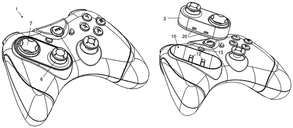
DETAILED DESCRIPTION OF EMBODIMENT(S) A gamepad1shown inFIG. 1comprises a base unit2and a module3mounted to the base unit. The base unit carries an analog stick4and a set of four action buttons5. The module3carries an analog stick6and a directional pad7(conventionally known as a D-pad). The gamepad1provides user input to a video game running on a game processor (not shown). The game processor may comprise a dedicated video game console such as a Sony Playstation™ or Microsoft Xbox™, or a more generic computing device such as an IBM PC™ or laptop. The analog sticks4,6and D-pad7act as direction controllers: that is, actuation signals generated in response to user input by the analog sticks4,6and D-pad7are generally used to control direction in the video game, such as the direction of movement of a person in a first-person shooting game. The actuation signals generated in response to user input by the action buttons5generally prompt an action in the video game, such as the firing of a shot in a first-person shooting game. The base unit2has a pair of hand grips8extending from its front, and a wire (also not shown) connecting the gamepad to the game processor extends from the rear of the base unit. The analog stick6and D-pad7are arranged in the orientation shown inFIG. 1; that is, with the D-pad7at the front-center position, and the analog stick6at the rear-left position. In this orientation the D-pad7is symmetrically opposite the analog stick4, enabling the D-pad7to be operated by the left thumb and the analog stick4to be operated by the right thumb. This configuration is commonly used in a conventional Xbox™ gamepad. The module3can be rotated between the orientation shown inFIG. 1to the orientation shown inFIG. 2, in which the analog stick6is at the front-center position. This configuration is commonly used in a conventional Playstation™ gamepad. Note that both the ...
DETAILED DESCRIPTION OF EMBODIMENT(S)
A gamepad1shown inFIG. 1comprises a base unit2and a module3mounted to the base unit. The base unit carries an analog stick4and a set of four action buttons5. The module3carries an analog stick6and a directional pad7(conventionally known as a D-pad).
The gamepad1provides user input to a video game running on a game processor (not shown). The game processor may comprise a dedicated video game console such as a Sony Playstation™ or Microsoft Xbox™, or a more generic computing device such as an IBM PC™ or laptop.
The analog sticks4,6and D-pad7act as direction controllers: that is, actuation signals generated in response to user input by the analog sticks4,6and D-pad7are generally used to control direction in the video game, such as the direction of movement of a person in a first-person shooting game. The actuation signals generated in response to user input by the action buttons5generally prompt an action in the video game, such as the firing of a shot in a first-person shooting game.
The base unit2has a pair of hand grips8extending from its front, and a wire (also not shown) connecting the gamepad to the game processor extends from the rear of the base unit.
The analog stick6and D-pad7are arranged in the orientation shown inFIG. 1; that is, with the D-pad7at the front-center position, and the analog stick6at the rear-left position. In this orientation the D-pad7is symmetrically opposite the analog stick4, enabling the D-pad7to be operated by the left thumb and the analog stick4to be operated by the right thumb. This configuration is commonly used in a conventional Xbox™ gamepad.
The module3can be rotated between the orientation shown inFIG. 1to the orientation shown inFIG. 2, in which the analog stick6is at the front-center position. This configuration is commonly used in a conventional Playstation™ gamepad. Note that both the analog stick6and D-pad7are accessible to a user, whether the module is in theFIG. 1orientation or theFIG. 2orientation. The rotation of the module is in the same plane as the base unit—i.e. horizontal if the base unit is being held horizontally.
The module3is housed in a recess10in the upper face of the base unit, shown inFIGS. 3,6and7. Two pairs of spring loaded latches12are provided at the base of the recess. The latches12engage with recesses20on each side of the module3, shown inFIGS. 4 and 5. A button13can be pressed to disengage the latches12and eject the module from the recess as shown inFIG. 3.
The base of the module, shown inFIG. 4, has a pair of recesses21,22which are offset from the center of the module by an equal distance D. Therefore the distance between the centers of the recesses21,22is 2D as illustrated inFIG. 4. A set of eight electrical pins23projects from the base of the recess21. This set of pins23carries actuation signals from both the analog stick6and the D-pad7. The base of the recess10in the base unit has two plugs14,15shown inFIG. 7, each carrying a set of eight electrical sockets, which are each offset from the center of the recess by the distance D. The plugs14,15slide into the module recesses21,22when the module is fitted to the base unit.
Each plug14,15forms a first half of a signal interface which couples the module to the base unit when the module is in a particular orientation. That is, when the module3is in the orientation ofFIG. 1the pins23are inserted into the sockets carried by the plug14, and when the module3is in the orientation ofFIG. 2the pins23are inserted into the sockets carried by the other plug15.
The plugs14,15each have respective output lines (not shown) which lead to a processor (not shown) in the base unit. The processor senses the orientation of the module by determining the presence of a signal on one or other of the output lines. The processor also acts as an interface between the video game and the various actuators on the game pad. An indication light16is illuminated a first colour when the module3is in the configuration ofFIG. 1, and a second colour when the module3is in the configuration ofFIG. 2.
Although the invention has been described above with reference to one or more preferred embodiments, it will be appreciated that various changes or modifications may be made without departing from the scope of the invention as defined in the appended claims.
Claims
- A video game controller comprising: a hand-held base unit including: at least one base unit actuator, each base unit actuator configured to generate a respective actuation signal in response to user input;at least one module-receiving feature defining an opening;and at least two first electrical connectors cooperating with the at least one module-receiving feature and the opening defined thereby;a module removably disposed relative to the opening defined by the module-receiving feature of the hand-held base unit and comprising: a single body;and two or more module actuators collectively carried by the single body, each module actuator configured to generate a respective actuation signal in response to user input;and at least two second electrical connectors collectively carried by the single body, each of the at least two second electrical connectors corresponding to a particular one of the two or more module activators, the single body of the module being configured to be coupled to the at least one module-receiving feature of the hand-held base unit, and at least partially within the opening, in two or more orientations relative to the hand-held base unit, each orientation of the single body of the module positioning the two or more module actuators relative to the at least one base unit actuator in a different configuration than each other orientation of the module relative to the hand-held base unit, each of the two or more module actuators being accessible to a user in each orientation of the module relative to the hand-held base unit, wherein in a first orientation, each of the at least two first electrical connectors connects to a respective one of the at least two second electrical connectors, and in a second orientation, each of the at least two first electrical connectors connects to a different one of the at least two electrical connectors.
- The controller of claim 1 , wherein the module or the hand-held base unit includes two or more first electrical connectors, each of the two or more first electrical connectors being configured to couple to and communicate with a single second electrical connector of the other of the module and the hand-held base unit.
- The controller of claim 2 , wherein the two or more first electrical connectors are associated with the at least one module-receiving feature of the hand-held base unit.
- The controller of claim 3 , wherein the module-receiving feature of the hand-held base unit comprises a recess in the hand-held base unit.
- The controller of claim 4 , wherein the two or more first electrical connectors are offset by substantially equal distances from an orientation center of the recess.
- The controller of claim 1 , wherein at least one of the two or more module actuators comprises a direction controller.
- The controller of claim 6 , wherein at least two of the two or more module actuators comprise direction controllers.
- The controller of claim 7 , wherein one of the directional controllers comprises a directional pad and another of the direction controllers comprises a stick.
- The controller of claim 1 , wherein the at least one base unit actuator comprises a direction controller.
- The controller of claim 1 , wherein the at least one base unit actuator is configured to be operated by a thumb of one hand of the user and, for each orientation of the module, at least one of the two or more module actuators is configured to be operated by a thumb of another hand of the user.
- The controller of claim 1 , wherein the at least one base unit actuator is positioned relative to a pair of hand grips so as to enable the at least one base unit actuator to be operated by a thumb of one hand of the user and, for each orientation of the module, the at least one module actuator of the two or more module actuators is positioned relative to the hand grips so as to enable the at least one module actuator to be operated by a thumb of another hand of the user.
- The controller of claim 1 , wherein the module is configured to be removably mounted to the hand-held base unit and to be rotated horizontally between the two or more orientations to modify the configuration of the two or more module actuators relative to the at least one base unit actuator.
- The controller of claim 1 , wherein the module-receiving feature of the base unit comprises a recess in the base unit.
- The controller of claim 13 , wherein the recess defines a plurality of discrete orientations for the module and the two or more module actuators relative to the base unit.
- A method of operating a video game controller, comprising: providing a hand-held video game controller with a module collectively carrying a plurality of module actuators coupled in a first orientation relative to a base unit of the video game controller, wherein in the first orientation a first electrical connector of the module is in electrical communication with a first electrical connector of a receiving portion of the base unit and a second electrical connector of the module is in electrical communication with a second electrical connector of the receiving portion of the base unit;disengaging the module from the receiving portion of the base unit;rotating the module from the first orientation to a different, second orientation relative to the base unit to change an orientation of the plurality of module actuators relative to the base unit and the receiving portion of the base unit;and recoupling the module to the same receiving portion of the base unit in the second orientation, including reestablishing electrical communication between the plurality of module actuators and the base unit such that the first electrical connector of the module is in electrical connection with the second electrical connector of the receiving portion of the base unit and the second electrical connector of the module is in electrical communication with the first electrical connector of the receiving portion of the base unit.
- A video game controller comprising: a hand-held base unit comprising at least one base unit actuator configured to generate an actuation signal in response to user input;and a module comprising two or more module actuators and two or more electrical connectors on a single body, each module actuator configured to generate a respective actuation signal in response to user input and convey the actuation signal to at least one respective electrical connector;wherein the module is removably mounted at least partially within an opening defined by the base unit, the module being configured to be rotated between two or more orientations in which the module is at least partially within the opening to change a configuration of the two or more module actuators and the two or more electrical connectors relative to the at least one base unit actuator.
- The method of claim 16 , further comprising: generating actuation signals with the at least one base unit actuator and at least two of the module actuators with the module in the second orientation.
- The method of claim 17 , further comprising: generating actuation signals with the at least one base unit actuator and at least two of the module actuators with the module in the first orientation, before disengaging the module from the base unit.
- The video game controller of claim 16 , wherein: the hand-held base unit includes at least one module receiving feature defining an opening;the module includes a module body that is selectively mountable relative to the at least one module receiving feature and at least partially within the opening;the two or more module actuators are configured to be collectively carried by the module body when the module is in each of the two or more orientations and when the module body is removed from the module receiving feature;and each of the two or more module actuators are mounted relative to the same one of the at least one module receiving feature and relative to the opening in each of the two or more orientations, such that in the at least two orientations, the module body is at least partially within the same opening.
- The video game controller of claim 19 , wherein in a second of the at least two orientations, the module body is rotated about a central axis about one-hundred eighty degrees relative to a position of the module body in a first orientation of the at least two orientations.
Disclaimer: Data collected from the USPTO and may be malformed, incomplete, and/or otherwise inaccurate.