U.S. Pat. No. 8,206,218
3D VIDEOGAME SYSTEM
AssigneeTDVision Corporation S.A. De C.V.
Issue DateFebruary 22, 2010
Illustrative Figure
Abstract
A 3D videogame system capable of displaying a left-right sequences through a different, independent VGA or video channel, with a display device sharing a memory in an immerse manner. The system has a videogame engine controlling and validating the image perspectives, assigning textures, lighting, positions, movements and aspects associated with each object participating in the game; creates left and right backbuffers, creates images and presents the information in the frontbuffers. The system allows handling the information of data associated to the xyz coordinates of the object's image in real-time, increases the RAM for the left-right backbuffer, with the possibility to discriminate and take the corresponding backbuffer, whose information is sent to the frontbuffer or additional independent display device sharing a memory in an immerse manner.
Description
DETAILED DESCRIPTION OF THE INVENTION Videogames are processes which start by providing a plurality of independently related logical states which include a set of programming options, where each programming option corresponds to different image characteristics. The generic program instructions can be compiled into a code by several computing devices, without having to independently generate the object codes for each device. The computer devices, such as personal computers, laptops, videogames, etc., include central processing units, memory systems, video graphical processing circuits, audio processing circuits and peripheral ports. Typically, the central processing unit processes software in order to generate geometric data referring to the image to be displayed and provides the geometric data to the video graphics circuit, which generates the pixel data stored in a memory frame where the information is sent to the display device. The aforementioned elements as a whole are typically called the videogame engine. Some video game engines are licensed to a third party, as in the case of the Quake III Arena® program, which has the QUAKE ENGINE game engine; this engine was licensed to the VOYAGER ELITE FORCE game which uses the quake engine. This way, the game developers can concentrate in the game metrics, instead of having to develop a game engine from scratch. Originally, videogames used only two-dimensional images, called “sprites”, which were the game's protagonists. Most of the videogames and technologies have evolved and now allow working with simulated objects in a three-dimensional environment or world, giving each object xyz position properties, surrounded by other objects with the same characteristics and acting together within a world with a (0,0,0) origin. At first, videogame consoles, separated from the computer world, took the first step to incorporate 3D graphics as a physical graphics capability of the devices. Techniques later were adopted by the hardware ...
DETAILED DESCRIPTION OF THE INVENTION
Videogames are processes which start by providing a plurality of independently related logical states which include a set of programming options, where each programming option corresponds to different image characteristics. The generic program instructions can be compiled into a code by several computing devices, without having to independently generate the object codes for each device.
The computer devices, such as personal computers, laptops, videogames, etc., include central processing units, memory systems, video graphical processing circuits, audio processing circuits and peripheral ports. Typically, the central processing unit processes software in order to generate geometric data referring to the image to be displayed and provides the geometric data to the video graphics circuit, which generates the pixel data stored in a memory frame where the information is sent to the display device. The aforementioned elements as a whole are typically called the videogame engine.
Some video game engines are licensed to a third party, as in the case of the Quake III Arena® program, which has the QUAKE ENGINE game engine; this engine was licensed to the VOYAGER ELITE FORCE game which uses the quake engine. This way, the game developers can concentrate in the game metrics, instead of having to develop a game engine from scratch. Originally, videogames used only two-dimensional images, called “sprites”, which were the game's protagonists.
Most of the videogames and technologies have evolved and now allow working with simulated objects in a three-dimensional environment or world, giving each object xyz position properties, surrounded by other objects with the same characteristics and acting together within a world with a (0,0,0) origin.
At first, videogame consoles, separated from the computer world, took the first step to incorporate 3D graphics as a physical graphics capability of the devices. Techniques later were adopted by the hardware used in PCs. A circumstance-analysis element is also included, usually known as videogame applied artificial intelligence. This element analyzes the situation, positions, collisions, game risks and advantages, and based on this analysis, generates a response action for each object participating in the videogame.
A backbuffer is used, which is a memory location where the image to be displayed is temporarily “drawn” without outputting it to the video card. If this is done directly on the video memory screen, a flicker on the screen would be observed; therefore the information is drawn and processed quickly in the backbuffer. This backbuffer is usually located within the physical RAM memory of the video or graphics acceleration card.
A typical sequence within a videogame's algorithm would be:
Display title screen
Load characters, objects, textures and sounds into memory
Create a memory location for temporary processing, called doublebuffer or backbuffer.
Display background
Record the image under each element participating in the game
Clean all elements from memory (doublebuffer)
User input verification and player's position update
Enemy position processing by means of artificial intelligence (AI)
Move every participant object to its new position
Objects collision verification
Animation frame increment
Draw objects in backbuffer memory
Transfer backbuffer data to the screen
Go back to step 5, unless the user wants to end the game (step 15)
Delete all objects from memory
End game.
The most commonly used devices in a video game console are: The CPU or Central Processing Unit, which handles the game loop, user input from the keyboard, mouse or game devices as a gamepad or joystick and the game's artificial intelligence processing.
The GPU or Graphics Processing Unit handles the polygon modeling, texture mapping, transformations and lighting simulation.
The audio DSP or Digital Signal Processor handles the background music, sound effects and 3D positional sounds.
The graphics engine is the game section in charge of controlling and validating perspectives, assigning textures (metal, skin, etc.), lighting, positions, movements and every other aspect associated to each object participating in the videogame, for a videogame console or PC. This image set is processed in relation to the assigned origin point and calculating the distance, depth and position perspectives. This is made in two steps, but it is a complex process due to the mathematical operations involved, namely, the object translation process (offset from origin), and the object rotation process (rotation angle in relation to the current position).
It is important to note that the minimum image units (FIG. 3) are comprised of minimum control units called a “vertex”, which represent one point in the xyz space. The minimum geometrical unit allowed is the triangle constructed by a minimum of three points in space; from the triangle base unit larger objects are formed, comprised of thousands of smaller triangles, as the Mario Sunshine character. This representation is called “Mesh” and texture, color and even graphical display characteristics can be associated to each mesh or even to each triangle. This information is denominated 3D graphics. It should be noted that even when it is called a 3D graphic due to its nature, constructed by xyz vectors, the final display to the user is generally in 2D, in a flat engine with content based on 3D vectors seen by the user as if they were in front of him, they only appear to have some intelligent depth and lighting characteristics, but for the brain they do not appear to have a volume in space.
Originally, it was necessary for the videogame programs to communicate directly with the graphics card to execute acceleration and complex mathematics operations, which meant that a game had to be practically rewritten in order to support a different video card. Facing this problem, Silicon Graphics® focused in developing a software layer (OpenGL®) which communicated directly with the hardware, with a series of useful functions and subroutines which, independently of the hardware, could communicate with it only in the graphical aspects. Microsoft® also developed a similar function group called DirecTX 3D, very much like OpenGL® but with a more complete functionality, as it included sound control and network gaming areas, among others.
These functions and subroutines set are called Graphics Applications Programming Interface (GRAPHICS API). These APIs can be accessed from different programming languages, as C, C++, Visual .Net, C# and Visual Basic, among others.
Every virtual reality system mentioned currently uses a left-right sequence through the same VGA or video channel scheme. These types of systems require software which includes specific instructions for alternating video images at on-screen display time in the backbuffer, applying a known offset algorithm using offsets and simulation-like angles.
Additionally to the functions provided by the OpenGL® and DirecTX® API, a series of graphics handling functions is available within an application-programming interface provided by Windows®, called WINDOWS API.
The development of a videogame program based on these technologies is shown inFIG. 4, in which the videogame software developed in the present application by TDVision® Corp. implementation is included.FIG. 4shows a schematic of the flowchart starting with the software implementation with the adequate metrics for the videogame (40), the software is developed in any appropriate programming language (such as C, C++, Visual Basic, Others) (41), the source code for the videogame (42), game logic and object characteristics, sounds, events, etc. are entered. (43), in (44) the event selector is located, which does this by means of the Windows API (45), OpenGL (46), or DirecTX (47), and is finally sent to the video display (48).
Although all of this refers to the software, something interesting is that DirecTX provides many functions, and Microsoft® achieved that even when initially some functions required specific hardware. The DirecTX API itself is capable of emulating the hardware characteristics by software, as if the hardware was actually present.
Embodiments of the present invention maximize and optimize the use of the OpenGL® and DirecTX® technologies, resulting in a software with certain specific characteristics, algorithms and digital processes in order to meet the specifications set by TDVision used in the present application.
Regarding the hardware, the Hal and the direct interface can be analyzed by drivers for each card, and in order to implement the TDVision technology the minimum specifications and requirements are analyzed, as well as any possible changes in the technology which allow it to obtain real 3D in TDVision's 3DVisors.
Regarding the display or representation systems, the information generated by the software and stored in the Graphic Device Context or Image Surface is transmitted directly to the last stage of the graphics card, which converts the digital video signal into analog or digital signals (depending on the display monitor), and the image is then displayed on screen.
The current display methods are:
Analog monitor with digital computer signal
Digital monitor
Analog monitor with TV signal
3D virtual reality systems.
The output type(s) depend on the video card, which should be connected to a compatible monitor.
FIG. 4ashows the creation of memory locations for the temporary graphics processing (left and right backbuffers) in which basically it adds an extra memory location, i.e., sets a right buffer in (400) and discriminates in (401) if TDVision technology is present; in an affirmative case, it sets the left buffer in (402) and ends in (403); when TDVision technology is not present the process ends at (403), as there was nothing to discriminate.
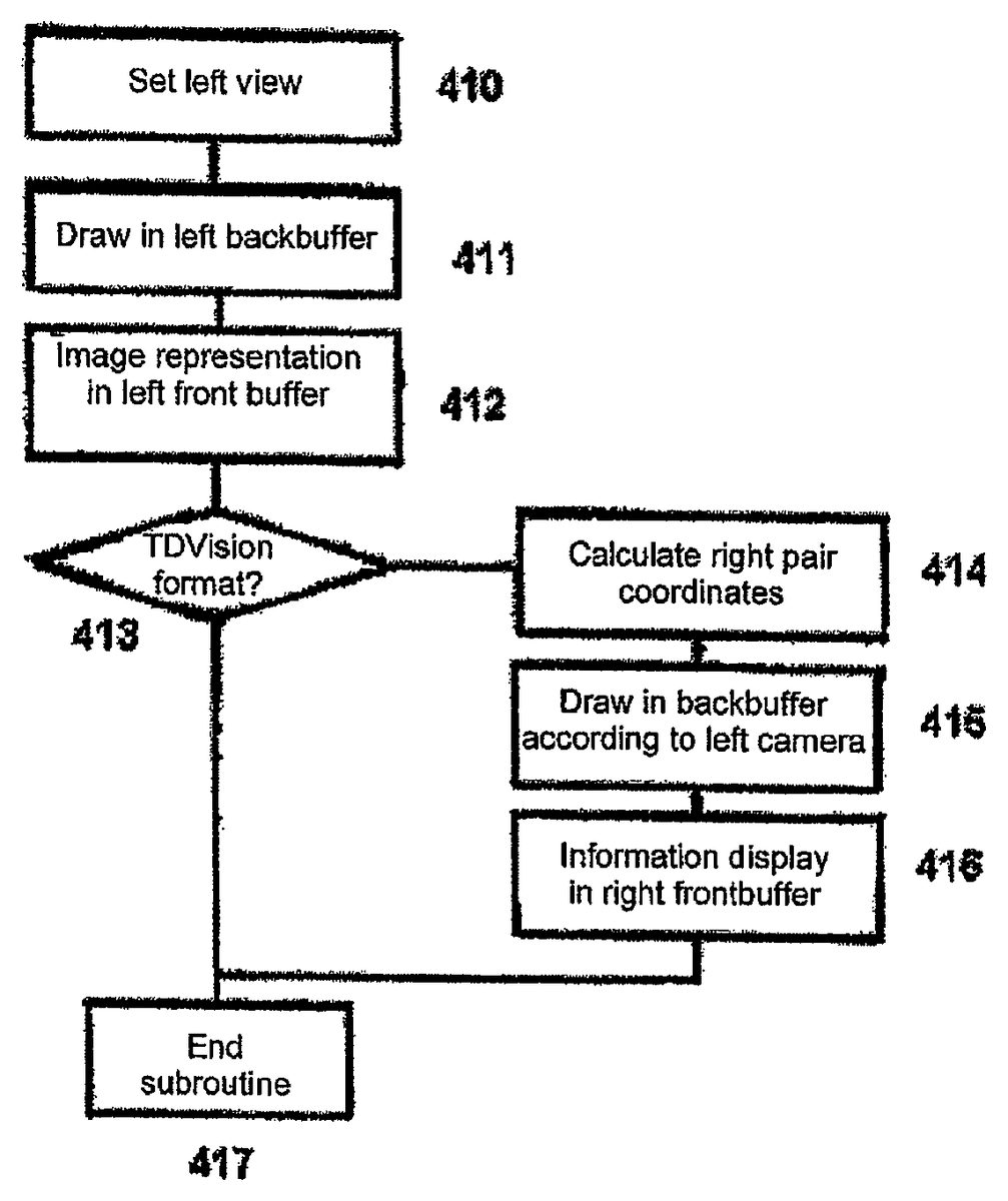
FIG. 4bshows the flowchart for the discrimination and display of the left camera and right camera image; the left view is set in (410), the image is drawn in the left backbuffer (411) as a function of the camera position, the image is displayed in the left screen (412), then it is discriminated if it has TDVision format in (413) and in the affirmative case the right view position coordinates are calculated (414), the image is drawn in the right backbuffer as a function of the left camera position (415), then the image is displayed in the right screen (416), the process ends at (417). If it is not necessary to discriminate in (413) as the image is provided in a current state-of-the-art format, the subroutine jumps to the final stage (417) and ends, as there is no need to calculate other coordinates and display parallel information. In one embodiment of the invention, the present application refers to the graphics-processing unit shown inFIG. 5(GPU HARDWARE), and to the graphics engine (GRAPHICS ENGINE, SOFTWARE)
The hardware modifications are:RAM increase for the left and right backbuffersImplementing an additional independent display device in the display buffer but sharing the memory in an immense manner so it takes the corresponding backbuffer.
In this case the backbuffer's RAM memory and the video card's frontbuffer are large enough to support the left and right channels simultaneously. In current embodiments, this requires a minimum of 32 MB in order to support four buffers with a depth of 1024×768×4 color depth bytes each. Additionally, the video output signal is dual-ported (two VGA ports), or has the capability of handling multiple monitors, as it is the case of the ATI RADEON 9500® card, which has two output display systems, one VGA and one S-Video video ports to choose from. A graphics card is used which has a dual output only to meet the 60 frames per second display per left-right channel in order to be connected to a 3DVisor, these outputs are SVGA, S-Video, RCA or DVideo type outputs.
The computing scheme is presented with modifications for TDV compilation as described inFIG. 5. A CPU (50), the memory driver (52), and the extended memory (52) feeds the audio driver (53) and the speakers (54). Also the input and output driver (55) which in turn control the disk ports (56) and the interactive elements with the user (57) as the mouse, keyboard, gamepad and joystick. The graphics driver interacts directly with the monitor (59) and the three-dimensional visors 3DVISORS (59b).
Concerning specifically the graphics hardware (HAL), changes are needed to compile the TDVision technology. For example, the application (500) sending the information to the graphics drivers (501) operating due to the graphics hardware support (502) effectively needs physical changes to be compiled with the TDVision technology. In order to implement the TDVision technology by means of OpenGL and DirecTX, modifications can be made in parts of the software section of a videogame as mentioned earlier, in some hardware sections.
Regarding the software, some special characteristics are added within a typical work algorithm, as well as a call to a TDVision subroutine, as it is shown inFIG. 6.Load surfaces information (600)Load meshes information (601)Create TDVision backbuffer (602) in which a left backbuffer is created in memory, if it is TDVision technology then it creates a right backbuffer in memory.Apply initial coordinates (603)Apply game logic (604)Validation and artificial intelligence (605)Position calculation (606)Collision verification (607)Drawing the information in the TDVision backbuffer and display on screen (608), in which the right camera view is set. Drawing the image in the right backbuffer as a function of the current right camera vector, and displaying the image on the right screen (front buffer). If it is TDVision technology, then: Calculate the left pair coordinates, set the left camera view, draw the image in the left backbuffer as a function of the current vector of the left camera, display the information on the right screen (front buffer) which may use hardware modification.
Thus, a pair of buffers corresponding to the left eye and right eye are created, which, when evaluated in the game loop get the vectorial coordinates corresponding to the visualization of each right camera (current) and the left camera (complement calculated with the SETXYZTDV function) shown below.
It should be realized that said screen output buffers or front buffers are assigned from the beginning to the video display surface (device context) or to the surface in question (surface), but for displaying the information in a TDVision 3Dvisor two video outputs should be physically present. The right output (normal VGA) and the left output (additional VGA, digital complement or S-Video) should be present in order to be compatible with TDVision. In the example DirecTX is used, but the same process and concept can be applied to the OpenGL format.
FIG. 7shows an outline of the algorithm (70) conducting a display line of the graphical applications communications interface, effectively, by means of trigonometry (72) with the vertex operations (77), the image is constructed (71) and by means of pixel operations or image elements (75) through the commands (73), the display list (74) and a memory which assigns a texture to the image (76), resulting in the display being sent to the memory frame (70F) by the operations (79). The Windows software (700) communicates with (702) and the graphic language card (701), which in turn contains a graphic information library, which is useful to feed (703) and (704).
FIG. 8shows the TDVision technology using the OpenGL algorithm (80) to display the left and right image for the object, it cleans the backbuffer (81), gets the pointer for the backbuffer (82), closes the backbuffer (83), redraws the scene (84), opens the backbuffer (85), unlocks the backbuffer pointer (86), sends the image to the left display surface; in (800) it discriminates if it is TDVision technology and in an affirmative case it cleans the memory (801) and gets a pointer for the backbuffer (802), closes the backbuffer (803), gets the coordinates for the new perspective (804), redraws the scene (805), opens the memory (806), unlocks the backbuffer pointer (807), and sends the image to the right display surface (808).
FIG. 9shows the changes (90) that can be made in the video card to compile TDVision technology. Namely, the left normal backbuffer (91) preceding the normal left primary backbuffer (92) which in turn is connected to the monitor's VGA output (95) and should have another VGA output so it can receive the right primary backbuffer (94), which in turn has the TDVision technology backbuffer as a precedent. Both left and right backbuffers can be connected to a 3DVisor (96) with a dual VGA input to receive and display the information sent by the backbuffers (91) and (93).
This software modifications use the following API functions in Direct X:
TDVision backbuffer creation:
FUNCTION CREATE BACKBUFFERTDV( )Left bufferSet d3dDevice = d3d.CreateDevice(D3DADAPTER_DEFAULT,—D3DDEVTYPE_HAL,hWndL,—D3DCREATE_SOFTWARE_VERTEXPROCESSING, d3dpp)If GAMEISTDV thenRight BufferSetd3dDeviceRight =d3d.CreateDevice(D3DADAPTER_DEFAULT,—D3DDEVTYPE_HAL,hWndR,—D3DCREATE_SOFTWARE_VERTEXPROCESSING, d3dpp2)EndifEND SUB
Draw image in TDVision backbuffer:
FUNCTION DRAWBACKBUFFERTDV( )DRAW LEFT SCENEd3dDivice.BeginScened3dDivece.SetStreamSource0, poly 1_vb, Len(poly1.v1)d3dDevice.DrawPrimitiveD3DPT_TRIANGLELIST,0,1d3dDevice.EndScene
Copy backbuffer to frontbuffer, screen
D3dDivice.Present By Val 0,By Val 0, 0, By Val 0‘VERIFIES IF IT IS A TDVISION PROGRAM BYCHECKING THE FLAGIF GAMEISTDV THEN‘CALCULATE COORDINATES RIGHT CAMERASETXYZTDV ( )′Draw right scened3dDevice2.BeginScened3dDevice2.Set StreamSource 0, poly2_vb, Len(poly1,v1)d3dDevice2.DrawPrimitive D3DPT_TRIANGLELIST,0,1d3dDevice2.EndScened3dDevice2.Present ByVal 0, ByVal 0, 0, ByValEND SUB.
Modifications to xyz camera vector:
VecCameraSource.z = z positionD3DXMatrixLook AtLH matView, vecCameraSource,—VecCameraTarget, CreateVector (0,1,0)D3dDevice 2.SetTransform D3DTS_VIEW, matViewVecCameraSource.x = x positionD3DXMatrixLook AtLH matView, vecCameraSource,—VecCameraTarget, CreateVector (0,1,0)D3dDevice 2.SetTransform D3DTS_VIEW, matViewVecCameraSource.y = y positionD3DXMatrixLook AtLH matView, vecCameraSource,—VecCameraTarget, CreateVector (0,1,0)D3dDevice 2.SetTransform D3DTS_VIEW, matView
Thus, a pair of buffers corresponding to the left eye and right eye are created, which, when evaluated in the game loop get the vectorial coordinates corresponding to the visualization of the right camera and the left camera (complement calculated with the SETXYZTDV function) by means of the usual coordinate transform equations.
It should be realized that the screen output buffers or front buffers are assigned from the beginning to the device context or to the surface in question, but for displaying the information in a TDVision 3Dvisor it is necessary that two video outputs are physically present, the right output (normal VGA) and the left output (additional VGA, digital complement or SVIDEO) in order to be compatible with TDVision.
The example was made using DirecTX, but the same process and concept can be applied for the OpenGL format shown inFIG. 8.
In this case the backbuffer's RAM memory and the video card's frontbuffer should be large enough to support the left and right channels simultaneously. Thus, they should use a minimum of 32 MB in order to support four backbuffers with a color depth of 1024×768×4 bytes each. As it was mentioned before, the video output signal is preferably dual (two VGA ports), or has the capability to handle multiple monitors, as it is the case of the ATI RADEON 9500® card, which has two output display systems, one VGA and one S-Video and one DVideo port to choose from.
A graphics card is created which has a dual output only to meet the 60 frames per second display per left-right channel in order to be connected to a 3DVisor, these outputs can be SVGA, S-Video, RCA or DVideo type outputs.
Therefore, the images corresponding to the camera viewpoint in both left and right perspectives can be obtained and the hardware will recognize the information to be displayed in two different and independent video outputs, without multiplexing and displayed in real-time. Presently, all the technologies use multiplexion and software simulation. In the technology proposed by the present application real information can be obtained and while using the 3Dvisors. The image can be displayed from two different perspectives and the brain will associate the volume it occupies in space, without any flickering on screen, effect associated to the current state-of-the-art technologies.
A coordinate calculation method of the secondary stereoscopic camera (SETXYZTDV( )) allows obtaining three-dimensional computer visual systems for the generation of stereoscopic images by animation, display and modeling in software programs. This method allows obtaining spatial coordinates (x, y, z) that are assigned to two computer-generated virtual visualization cameras to obtain a stereoscopic vision by using any software program that simulates the third dimension and generates the images by means of the object's movement, or by the “virtual camera” movement observed at that moment by the computer-generated object. Examples include: Autocad, Micrografix Simply 3D, 3Dmax Studio, Point, Dark Basic, Maya, Marionette, Blender, Excel, Word, Paint, Power, Corel Draw, Photo paint, Photoshop, etc. However, all of these programs are designed to display only one camera with one fixed or moving perspective.
An additional 3D modeling and animation characteristic is added to the previous programs by means of the coordinate transformation equations, namely:
x=x′ cos φ−y′ sin φ
y=x′ sin φ+y′ cos φ
The exact position is calculated for a second or secondary camera, directly linked to the first camera and by this means two simultaneous images are obtained from different perspectives simulating the human being's stereoscopic visual perspective. This procedure, by means of an algorithm, calculates in real-time the position of the secondary camera to place it in the adequate position, and to obtain the modeling image and representation of the second camera, achieved using the coordinate transforming equations, taking the camera to the origin the angle and distance between the secondary camera and the object or objective are calculated, then the primary camera, objective and secondary camera are repositioned in the obtained position. Then, seven parameters need to be known, namely, the first coordinates (Xp, Yp, Zp) of the primary camera in the original coordinate system, the fourth parameter is the equivalent distance to the average separation of the eyes (6.5 to 7.0 cm), and the three coordinates of the objective's position when observed by the cameras.
The output parameters will be the coordinates of the secondary camera observing the same objective point, i.e., (Xs, Ys, Zs), obtained following these steps:Knowing the coordinates of the primary camera in the original coordinate system (Xp, Yp, Zp),
Knowing the objective's coordinates (xt, yt, zt)Only the “x” and “z” coordinates are transformed, as the coordinate and/or height of the camera is kept constant (there is no visual deviation for the observer)
The coordinates for the primary camera are taken to the (0, ys,0) position.
The objective is also translated
The slope for the line connecting the camera and the objective is calculated
The angle between the axis and the vector joining the primary camera with the objective is created.
The quadrant to which it belongs for the application of special considerations in the angle's calculation is classified by an inverse tangent function.
New coordinates are obtained, rotating the whole coordinate system from its axis in the same angle between the axis and the vector, a new coordinate system is obtained in which the object is placed on the ‘z’ axis and the primary camera will remain at the origin of the new coordinate system.
The coordinates of the secondary camera are obtained by placing it in the human eyes' average distance position
These coordinates are rotated in the same initial angle
The “x” and “z” offsets are added, which were originally subtracted to take the primary camera to the origin
Finally, these two new Xsy Zscoordinates are assigned to the secondary camera and the yp coordinate is maintained, which determines the height for the same value of a final coordinates point (Xs, Yp, Zs) to be assigned to the secondary camera.
The procedure can be implemented in languages as Delphi, C, C++, Visual C++, Omnis, etc., but the result will be the same.
The generalized application of this algorithm will be used in any program requiring to obtain in real-time the position of a secondary camera.
This algorithm must be implemented in any existing software which handles two dimensions but has been developed for stereoscopic vision applications.
The particular embodiments of the invention have been illustrated and described, for the technical experts it will be evident that several modifications or changes can be made without exceeding the scope of the present invention. The attached claims intend to cover the aforementioned information so that all the changes and modifications are within the scope of the present invention.
Claims
- A method in a videogame system for displaying three-dimensional images, comprising the computer implemented steps of: providing left and right backbuffers;calculating first position coordinates of a first eye view;storing a first eye view image captured virtually from the calculated first position coordinates of the first eye view of an object in the videogame into the left backbuffer;calculating, with a processor of the videogame system, second position coordinates of a second eye view of the object in three dimensional space using the calculated first position coordinates of the first eye view;determining a second eye view image of the object captured virtually from the calculated second position coordinates of the second eye view;storing the second eye view image in the right backbuffer;and displaying the first eye view image and the second eye view image to the user to provide a three dimensional perspective of the object from the videogame system to a user.
- The method according to claim 1 , wherein the first eye view image corresponds to a first virtual object in the videogame.
- The method according to claim 1 , wherein calculating the second position coordinates comprises calculating the x and z coordinates of the second eye view only so that there is no deviation in the height of the second eye view in relation to the height of the first eye view.
- The method according to claim 1 , wherein calculating the second position coordinates of the second view image comprises calculating the coordinates of a right eye camera view position.
- The method according to claim 1 , wherein calculating the second position coordinates of the second eye view comprises obtaining spatial coordinates by coordinate transformation equations given the location of a first virtual camera corresponding to the first eye view.
- The method according to claim 1 , wherein displaying the images in the left and right backbuffers comprises generating left and right images on different video channels.
- A method in a videogame system for displaying three-dimensional images, comprising the computer implemented steps of: providing first and second buffers;calculating first position coordinates of a first eye view;storing a first eye view image captured virtually from the calculated first position of the first eye view of a virtual object in the videogame into the first buffer;calculating, with a processor of the videogame system, second spatial coordinates of a second eye view of the virtual object in the videogame in three dimensional space by coordinate transformation equations using the calculated first position coordinates of the first eye view and the position of the virtual object in the videogame;determining a second eye view image of the virtual object based on the calculated second spatial coordinates;storing the second eye view image in the second buffer;and outputting the first eye view image from the first buffer and the second eye view image from the second buffer to a display to provide a three dimensional perspective of the virtual object from the videogame system to a user.
- The method according to claim 7 , further comprising increasing the first and second buffer memory size prior to generating the first eye view image and second eye view image in the videogame.
- The method according to claim 7 , wherein calculating the second spatial coordinates comprises calculating the x and z coordinates only so that there is no deviation in the height of the second eye view of the virtual object with respect to the first eye view of the virtual object.
- The method according to claim 7 , wherein calculating the second spatial coordinates of the second view image of the virtual object comprises calculating the spatial coordinates of a right eye camera view position.
- The method according to claim 7 , wherein the first and second buffers are located in the memory of a video graphics card.
- The method according to claim 7 , wherein storing the first eye view image to the first buffer and storing the second eye view image to the second buffer reduces flicker of the images on the display.
- The method according to claim 7 , further comprising: cleaning the first and second buffers;closing the first and second buffers;redrawing a scene comprising the virtual object;getting coordinates of a new perspective of the virtual object;and redisplaying the virtual object at the new perspective.
- The method of claim 7 , wherein the calculation of the second spatial coordinates of the second eye view comprises placing the second eye view at a virtual position that is 6.5 to 7.0 cm apart from the calculated position coordinates of the first eye view.
- The method of claim 7 , wherein calculating the second spatial coordinates of the second eye view comprises calculating the slope of a line from a virtual camera positioned at the second spatial coordinates of the second eye view to the virtual object.
- A videogame system for displaying three-dimensional images, comprising: first and second buffers;means for calculating first position coordinates of a first eye view of a virtual object in the videogame system;means for storing a first eye view image captured virtually from the calculated first position of the first eye view of the virtual object in the videogame into the first buffer;means for calculating second spatial coordinates of a second eye view of the virtual object in the videogame in three dimensional space by coordinate transformation equations using the calculated first position coordinates of the first eye view and the position of the virtual object in the videogame;means for determining a second eye view image of the virtual object captured virtually from the calculated second spatial coordinates of the second eye view;means for storing the second eye view image in the second buffer;and means for outputting the first eye view image from the first buffer and the second eye view image from the second buffer to a display to provide a three dimensional perspective of the virtual object from the videogame system to a user.
- The videogame system of claim 16 , wherein the first and second buffers are part of a memory of a video graphics card.
- The videogame system of claim 16 , wherein the means for calculating second spatial coordinates comprises a programmable processor.
- The videogame system of claim 16 , wherein the display is a stereoscopic visor.
Disclaimer: Data collected from the USPTO and may be malformed, incomplete, and/or otherwise inaccurate.