U.S. Pat. No. 8,203,561
DETERMINING VALUED EXCURSION CORRIDORS IN VIRTUAL WORLDS
AssigneeInternational Business Machines Corporation
Issue DateSeptember 10, 2008
Illustrative Figure
Abstract
A computer implemented method, computer program product, and a data processing system determine an excursion corridor within a virtual environment. A time-stamped snapshot of a location of at least one avatar within the virtual universe is recorded. An avatar tracking data structure is then updated. The avatar tracking data structure provides a time-based history of avatar locations within the virtual universe. A weighted density map is generated. The weighted density map is then correlated with virtual object locations. Each virtual object location corresponds to a virtual object. Excursion corridors are identified. The excursion corridor identifies frequently taken routes between the virtual object locations. Waypoints are identified. Each waypoint corresponds to a virtual object. Each waypoint is an endpoint for one of the excursion corridors.
Description
DETAILED DESCRIPTION OF THE INVENTION As will be appreciated by one skilled in the art, the present invention may be embodied as a system, method, or computer program product. Accordingly, the present invention may take the form of an entirely hardware embodiment, an entirely software embodiment (including firmware, resident software, micro-code, etc.) or an embodiment combining software and hardware aspects that may all generally be referred to herein as a “circuit,” “module” or “system.” Furthermore, the present invention may take the form of a computer program product embodied in any tangible medium of expression having computer usable program code embodied in the medium. Any combination of one or more computer usable or computer readable medium(s) may be utilized. The computer-usable or computer-readable medium may be, for example but not limited to, an electronic, magnetic, optical, electromagnetic, infrared, or semiconductor system, apparatus, device, or propagation medium. More specific examples (a non-exhaustive list) of the computer-readable medium would include the following: an electrical connection having one or more wires, a portable computer diskette, a hard disk, a random access memory (RAM), a read-only memory (ROM), an erasable programmable read-only memory (EPROM or Flash memory), an optical fiber, a portable compact disc read-only memory (CDROM), an optical storage device, a transmission media such as those supporting the Internet or an intranet, or a magnetic storage device. Note that the computer-usable or computer-readable medium could even be paper or another suitable medium upon which the program is printed, as the program can be electronically captured, via, for instance, optical scanning of the paper or other medium, then compiled, interpreted, or otherwise processed in a suitable manner, if necessary, and then stored in a computer memory. In the context of this document, a computer-usable or computer-readable medium may be any medium that can contain, store, ...
DETAILED DESCRIPTION OF THE INVENTION
As will be appreciated by one skilled in the art, the present invention may be embodied as a system, method, or computer program product. Accordingly, the present invention may take the form of an entirely hardware embodiment, an entirely software embodiment (including firmware, resident software, micro-code, etc.) or an embodiment combining software and hardware aspects that may all generally be referred to herein as a “circuit,” “module” or “system.” Furthermore, the present invention may take the form of a computer program product embodied in any tangible medium of expression having computer usable program code embodied in the medium.
Any combination of one or more computer usable or computer readable medium(s) may be utilized. The computer-usable or computer-readable medium may be, for example but not limited to, an electronic, magnetic, optical, electromagnetic, infrared, or semiconductor system, apparatus, device, or propagation medium. More specific examples (a non-exhaustive list) of the computer-readable medium would include the following: an electrical connection having one or more wires, a portable computer diskette, a hard disk, a random access memory (RAM), a read-only memory (ROM), an erasable programmable read-only memory (EPROM or Flash memory), an optical fiber, a portable compact disc read-only memory (CDROM), an optical storage device, a transmission media such as those supporting the Internet or an intranet, or a magnetic storage device. Note that the computer-usable or computer-readable medium could even be paper or another suitable medium upon which the program is printed, as the program can be electronically captured, via, for instance, optical scanning of the paper or other medium, then compiled, interpreted, or otherwise processed in a suitable manner, if necessary, and then stored in a computer memory. In the context of this document, a computer-usable or computer-readable medium may be any medium that can contain, store, communicate, propagate, or transport the program for use by or in connection with the instruction execution system, apparatus, or device. The computer-usable medium may include a propagated data signal with the computer-usable program code embodied therewith, either in baseband or as part of a carrier wave. The computer usable program code may be transmitted using any appropriate medium, including, but not limited to wireless, wireline, optical fiber cable, RF, etc.
Computer program code for carrying out operations of the present invention may be written in any combination of one or more programming languages, including an object oriented programming language such as Java, Smalltalk, C++ or the like and conventional procedural programming languages, such as the “C” programming language or similar programming languages. The program code may execute entirely on the user's computer, partly on the user's computer, as a stand-alone software package, partly on the user's computer and partly on a remote computer or entirely on the remote computer or server. In the latter scenario, the remote computer may be connected to the user's computer through any type of network, including a local area network (LAN) or a wide area network (WAN), or the connection may be made to an external computer (for example, through the Internet using an Internet Service Provider).
The present invention is described below with reference to flowchart illustrations and/or block diagrams of methods, apparatus (systems), and computer program products according to embodiments of the invention. It will be understood that each block of the flowchart illustrations and/or block diagrams, and combinations of blocks in the flowchart illustrations and/or block diagrams, can be implemented by computer program instructions.
These computer program instructions may be provided to a processor of a general purpose computer, special purpose computer, or other programmable data processing apparatus to produce a machine, such that the instructions, which execute via the processor of the computer or other programmable data processing apparatus, create means for implementing the functions/acts specified in the flowchart and/or block diagram block or blocks. These computer program instructions may also be stored in a computer-readable medium that can direct a computer or other programmable data processing apparatus to function in a particular manner, such that the instructions stored in the computer-readable medium produce an article of manufacture including instruction means which implement the function/act specified in the flowchart and/or block diagram block or blocks.
The computer program instructions may also be loaded onto a computer or other programmable data processing apparatus to cause a series of operational steps to be performed on the computer or other programmable apparatus to produce a computer implemented process such that the instructions which execute on the computer or other programmable apparatus provide processes for implementing the functions/acts specified in the flowchart and/or block diagram block or blocks.
With reference now to the figures and in particular with reference toFIGS. 1-2, exemplary diagrams of data processing environments are provided in which illustrative embodiments may be implemented. It should be appreciated thatFIGS. 1-2are only exemplary and are not intended to assert or imply any limitation with regard to the environments in which different embodiments may be implemented. Many modifications to the depicted environments may be made.
FIG. 1depicts a pictorial representation of a network of data processing systems in which illustrative embodiments may be implemented. Network data processing system100is a network of computers in which the illustrative embodiments may be implemented. Network data processing system100contains network102, which is the medium used to provide communications links between various devices and computers connected together within network data processing system100. Network102may include connections, such as wire, wireless communication links, or fiber optic cables.
In the depicted example, server104and server106connect to network102along with storage unit108. In addition, clients110,112, and114connect to network102. Clients110,112, and114may be, for example, personal computers or network computers. In the depicted example, server104provides data, such as boot files, operating system images, and applications to clients110,112, and114. Clients110,112, and114are clients to server104in this example. Network data processing system100may include additional servers, clients, and other devices not shown.
Program code located in network data processing system100may be stored on a computer recordable storage medium and downloaded to a data processing system or other device for use. For example, program code may be stored on a computer recordable storage medium on server104and downloaded to client110over network102for use on client110.
In the depicted example, network data processing system100is the Internet with network102representing a worldwide collection of networks and gateways that use the Transmission Control Protocol/Internet Protocol (TCP/IP) suite of protocols to communicate with one another. At the heart of the Internet is a backbone of high-speed data communication lines between major nodes or host computers, consisting of thousands of commercial, governmental, educational, and other computer systems that route data and messages. Of course, network data processing system100also may be implemented as a number of different types of networks, such as for example, an intranet, a local area network (LAN), or a wide area network (WAN).FIG. 1is intended as an example, and not as an architectural limitation for the different illustrative embodiments.
With reference now toFIG. 2, a block diagram of a data processing system is shown in which illustrative embodiments may be implemented. Data processing system200is an example of a computer, such as server104or client110inFIG. 1, in which computer usable program code or instructions implementing the processes may be located for the illustrative embodiments. In this illustrative example, data processing system200includes communications fabric202, which provides communications between processor unit204, memory206, persistent storage208, communications unit210, input/output (I/O) unit212, and display214.
Processor unit204serves to execute instructions for software that may be loaded into memory206. Processor unit204may be a set of one or more processors or may be a multi-processor core, depending on the particular implementation. Further, processor unit204may be implemented using one or more heterogeneous processor systems in which a main processor is present with secondary processors on a single chip. As another illustrative example, processor unit204may be a symmetric multi-processor system containing multiple processors of the same type.
Memory206and persistent storage208are examples of storage devices. A storage device is any piece of hardware that is capable of storing information either on a temporary basis and/or a permanent basis. Memory206, in these examples, may be, for example, a random access memory or any other suitable volatile or non-volatile storage device. Persistent storage208may take various forms depending on the particular implementation. For example, persistent storage208may contain one or more components or devices. For example, persistent storage208may be a hard drive, a flash memory, a rewritable optical disk, a rewritable magnetic tape, or some combination of the above. The media used by persistent storage208also may be removable. For example, a removable hard drive may be used for persistent storage208.
Communications unit210, in these examples, provides for communications with other data processing systems or devices. In these examples, communications unit210is a network interface card. Communications unit210may provide communications through the use of either or both physical and wireless communications links.
Input/output unit212allows for input and output of data with other devices that may be connected to data processing system200. For example, input/output unit212may provide a connection for user input through a keyboard and mouse. Further, input/output unit212may send output to a printer. Display214provides a mechanism to display information to a user.
Instructions for the operating system and applications or programs are located on persistent storage208. These instructions may be loaded into memory206for execution by processor unit204. The processes of the different embodiments may be performed by processor unit204using computer implemented instructions, which may be located in a memory, such as memory206. These instructions are referred to as program code, computer usable program code, or computer readable program code that may be read and executed by a processor in processor unit204. The program code in the different embodiments may be embodied on different physical or tangible computer readable media, such as memory206or persistent storage208.
Program code216is located in a functional form on computer readable media218that is selectively removable and may be loaded onto or transferred to data processing system200for execution by processor unit204. Program code216and computer readable media218form computer program product220in these examples. In one example, computer readable media218may be in a tangible form, such as, for example, an optical or magnetic disc that is inserted or placed into a drive or other device that is part of persistent storage208for transfer onto a storage device, such as a hard drive that is part of persistent storage208. In a tangible form, computer readable media218also may take the form of a persistent storage, such as a hard drive, a thumb drive, or a flash memory that is connected to data processing system200. The tangible form of computer readable media218is also referred to as computer recordable storage media. In some instances, computer recordable media218may not be removable.
Alternatively, program code216may be transferred to data processing system200from computer readable media218through a communications link to communications unit210and/or through a connection to input/output unit212. The communications link and/or the connection may be physical or wireless in the illustrative examples. The computer readable media also may take the form of non-tangible media, such as communications links or wireless transmissions containing the program code.
In some illustrative embodiments, program code216may be downloaded over a network to persistent storage208from another device or data processing system for use within data processing system200. For instance, program code stored in a computer readable storage medium in a server data processing system may be downloaded over a network from the server to data processing system200. The data processing system providing program code216may be a server computer, a client computer, or some other device capable of storing and transmitting program code216.
The different components illustrated for data processing system200are not meant to provide architectural limitations to the manner in which different embodiments may be implemented. The different illustrative embodiments may be implemented in a data processing system including components in addition to or in place of those illustrated for data processing system200. Other components shown inFIG. 2can be varied from the illustrative examples shown.
The different embodiments may be implemented using any hardware device or system capable of executing program code. As one example, the data processing system may include organic components integrated with organic components and/or may be comprised entirely of organic components excluding a human being. For example, a storage device may be comprised of an organic semiconductor.
As another example, a storage device in data processing system200is any hardware apparatus that may store data. Memory206, persistent storage208, and computer readable media218are examples of storage devices in a tangible form.
In another example, a bus system may be used to implement communications fabric202and may be comprised of one or more buses, such as a system bus or an input/output bus. Of course, the bus system may be implemented using any suitable type of architecture that provides for a transfer of data between different components or devices attached to the bus system. Additionally, a communications unit may include one or more devices used to transmit and receive data, such as a modem or a network adapter. Further, a memory may be, for example, memory206or a cache such as found in an interface and memory controller hub that may be present in communications fabric202.
The illustrative embodiments herein describe a method for discovering valued excursion corridors within a virtual world. Sighted users within a virtual world tend to travel purposefully using visual landmarks, even when performing an initial exploration of the virtual environment. Routes which are frequently taken by the avatars of these sighted users may represent valuable information for blind users. The cumulative travel route histories may be deemed as an interconnected set of invisible “beaten paths” which have previously been most commonly used by avatars in navigating through the virtual environment. Each path is not only a route which many other avatars have not only successfully traveled, but also is a pathway which users of those avatars valued for some reason. These paths can be offered to blind users as a set of excursion corridors.
A user can choose from a set of excursion corridors proximately located to the user's avatar. The chosen excursion corridor can be selected from a menu listing the nearby virtual paths, as well as their related endpoints, or points-of-interest that lie along the excursion corridor. Once the excursion corridor is selected, the user could be automatically navigated along the excursion corridor. Conversely, a set of navigational cues could be provided to the user that would enable the user to maintain travel along the selected excursion corridor. The navigational cues could be a visual cues, such as a luminescent trail, a three dimensional network of lines, a texture overlay, a discolored ground appearance depicting a “worn” pathway. The navigational cues could also be auditory cues, such as a tone or audio signal to alert the user of when the avatar is within the selected excursion corridor, or has wandered too far off of the selected excursion corridor.
Referring now toFIG. 3, virtual universe server300is a server such as server104or106. Virtual universe server300executes software to enable a virtual universe, and to allow clients to connect to, and interact within the virtual universe. Virtual universe server300stores all of the state information related to each virtual object, avatar, and landscape configuration. At any point in time, the virtual universe server knows the location of each avatar within the virtual environment.
According to an illustrative embodiment, virtual universe server300includes virtual universe monitoring software310. Virtual universe monitoring software310can be implanted as part of the software enabling the virtual universe, or can be implemented as a stand alone, or plug in application that works in conjunction with the software enabling the virtual universe.
Virtual universe monitoring software310includes avatar tracking data structure312. Avatar tracking data structure312is a data structure containing a time-based history of avatar locations throughout the virtual environment. Avatar tracking data structure312can be a data base, a linked list, a hash table, or other data structure capable of containing a time-based history of avatar locations throughout the virtual environment. The virtual universe server knows the location of each avatar within the virtual environment, and records those positions at certain time intervals. Thus, virtual universe monitoring software310can include avatar identification, as well as a location and time stamp. The location of an avatar can be implemented as a Cartesian, or other coordinate based system for easily representing a location within the virtual environment. The time stamp is provided at regular intervals, such as at the end of a clock-tic.
In one illustrative embodiment, entries within avatar tracking data structure312have a limited shelf life, and will expire after a duration of time has elapsed. Once an entry in avatar tracking data structure312has expired, it is removed from avatar tracking data structure312. By allowing entries within avatar tracking data structure312to expire, virtual universe monitoring software310ensures that older avatar location information is not used in determining an excursion corridor.
Virtual universe monitoring software310includes virtual object table314. Virtual object table314is a data structure that includes various virtual objects and their locations within the virtual environment. Virtual object table314is different from avatar tracking data structure312, since virtual object table314includes those objects that are persistent, or semi-persistent within the virtual environment. That is, virtual object table314contains location information for non-avatar virtual objects. The location of a virtual object can be implemented as a Cartesian, or other coordinate based system for easily representing a location within the virtual environment.
Virtual universe monitoring software310includes object correlation software316that is used to generate weighted density map318. Object correlation software316evaluates the historical avatar positions and their relative time-stamps to determine correlations amongst the activities of the various users in space and time. By weighing the frequency with which the various avatars visit certain locations, as well as the cumulative amount of time that an avatar spends at those certain locations, object correlation software316generates weighted density map318. Weighted density map318is a time lapse representation of avatar location.
A regression analysis of the various avatar locations from within the avatar tracking data structure can therefore yield excursion corridors322. Excursion corridors322are those frequently taken routes between various locations and points-of-interest within the virtual environment.
By comparing the locations of avatars within avatar tracking data structure312to the locations of virtual objects within virtual object table314, object correlation software316can determine waypoints320. Waypoints320are those virtual objects at which avatars congregate or linger. Waypoints320are thus the most probable end points for excursion corridors322. Waypoints320can be any virtual object, but will typically be fixed object locations, such as a virtual building, or a virtual meeting place.
Client324accesses the virtual environment by executing virtual universe software326. Waypoints320can be offered to client324as a set of selectable choices from within a graphical user interface of virtual universe software326. Waypoints320which lie along excursion corridors322facilitate navigation to popular locations and points-of-interest within the virtual environment.
Excursion corridors322may be rendered visually to client324. Excursion corridors322may be rendered as a luminescent pathway on the ground, or in the air. The thickness or brightness of the luminescent pathway can indicate the relative popularity of excursion corridor322. A brighter or wider luminescent pathway can indicate a greater number of avatars that have previously navigated excursion corridor322, while a fainter or narrower luminescent pathway can indicate a fewer number of avatars that have previously navigated excursion corridor322.
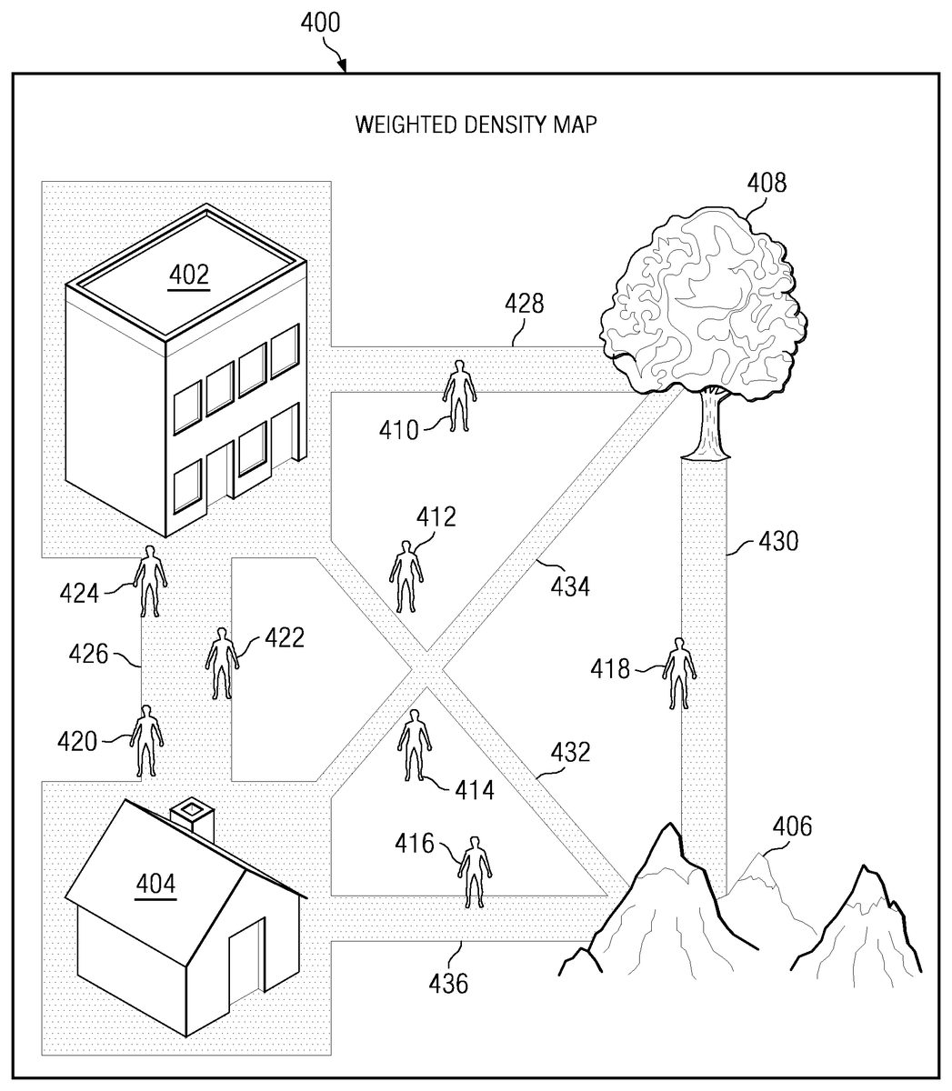
Referring now toFIG. 4, an isometric representation of a weighted density map of a virtual universe having excursion corridors and waypoints therein is shown according to an illustrative embodiment. Weighted density map400can be weighted density map318ofFIG. 3.
Weighted density map400includes virtual objects402,404,406, and408. Each of virtual objects402,404,406, and408are represented at various locations within weighted density map400. The various locations of virtual objects402,404,406, and408are stored in a virtual object table, such as virtual object table314ofFIG. 3.
Avatars410-424navigate through the virtual universe. As the avatars navigate the virtual universe, a virtual universe monitoring software, such as virtual universe monitoring software310ofFIG. 3, monitors the locations of avatars410-424. The locations of the avatars410-424are then stored in an avatar tracking data structure, such as avatar tracking data structure312ofFIG. 3.
The recorded locations of avatars410-424within avatar tracking data structure312are then used to calculate excursion corridors426-436. Excursion corridors426-436can be an excursion corridor such as excursion corridor322ofFIG. 3. Excursion corridors426-436are those frequently taken routes between various locations and points-of-interest within the virtual environment.
As shown, excursion corridor426is a navigable route between virtual object402and virtual object404. Excursion corridor428is a navigable route between virtual object402and virtual object408. Excursion corridor430is a navigable route between virtual object406and virtual object406. Excursion corridor432is a navigable route between virtual object402and virtual object406. Excursion corridor434is a navigable route between virtual object404and virtual object408. Excursion corridor446is a navigable route between virtual object404and virtual object406.
Excursion corridors426-436may be rendered as a luminescent pathway on the ground, or in the air. The thickness or brightness of the luminescent pathway can indicate the relative popularity of excursion corridors426-436. Excursion corridor426is a brighter or wider luminescent pathway indicating a greater number of avatars that have previously navigated excursion corridor426. Excursion corridor434is a fainter or narrower luminescent pathway indicating a fewer number of avatars that have previously navigated excursion corridor320.
In one illustrative embodiment an avatar can selectively filter the excursion corridors that are presented in the user interface based on the relative popularity of that excursion corridor. A more popular excursion corridor may indicate a more efficient route for navigating between two points. Conversely, a user may wish to take “the road less traveled,” and prefer to navigate along a less popular excursion corridor.
Thus the user may choose to apply a high pass excursion corridor filter, a low pass excursion corridor filter, or a band pass excursion corridor filter to the available excursion corridors. If the user selects to utilize a high pass excursion corridor filter, the user is presented with only those excursion corridors that have been traveled by more than some minimum number of avatars. By selecting a high pass excursion corridor filter, the user would be preferentially presented with the most popular excursion corridors proximate to the user's location.
If the user selects to utilize a low pass excursion corridor filter, the user is presented with only those excursion corridors that have been traveled by less than some maximum number of avatars. By selecting a low pass excursion corridor filter, the user would be preferentially presented with those less popular excursion corridors proximate to the user's location. By following these less popular excursion corridors, the user could “take the scenic route.”
If the user selects to utilize a band pass excursion corridor filter, the user is presented with only those excursion corridors that have been traveled by some number of avatars between both a minimum number of avatars and a maximum number of avatars. Users selecting a band pass excursion corridor filter may wish to not travel on the most popular of routes, but still navigate in a more directed manner than might be navigated on the least popular of excursion corridors.
In one illustrative embodiment, a user may wish to give preference to those excursion corridors that correspond to certain other avatars. Thus, the paths traveled by a friend, colleague, guide, or other preferred avatar could be preferentially weighted in determining weighted density map400. These preferred avatars would have a greater cumulative effect on weighted density map400than would non-preferred avatars.
Referring now toFIG. 5, a process for generating a weighted density map including waypoints and excursion corridors is shown according to an illustrative embodiment. Process500is a software process, executing on a software component, such as virtual universe monitoring software310ofFIG. 3.
Process500begins by recording a snapshot of the location of avatars within the virtual universe virtual universe (step510). The snapshot is a time-stamped location of avatars within the virtual universe.
Responsive to recording the snapshot, process500updates the avatar tracking data structure (step520). The avatar tracking data structure can be avatar tracking data structure312ofFIG. 3. Process500updates the avatar tracking data structure by storing the time-stamped present location of the avatars within the tracking table. Process500may further update the avatar tracking data structure by deleting expired time-stamped locations from the avatar tracking data structure.
Responsive to updating the avatar tracking data structure, process500calculates a weighted density map (step530). The weighted density map can be weighted density map318ofFIG. 3.
Responsive to generating the weighted density map, process500correlates the weighted density map with virtual object locations (step540). Virtual object locations are the location information for non-avatar virtual objects. The location of a virtual object can be implemented as a Cartesian, or other coordinate based system for easily representing a location within the virtual environment. Virtual object locations are retrieved from a virtual object table, such as virtual object table314ofFIG. 3.
Responsive to correlating the weighted density map with virtual object locations, process500identifies excursion corridors, waypoints, and points-of-interest (step550), with the process terminating thereafter. Process500can perform a regression analysis of the various avatar locations from within the avatar tracking data structure to yield the excursion corridors. The excursion corridors are those frequently taken routes between various locations and points-of-interest in the virtual environment. By comparing the locations of avatars within the avatar tracking data structure to the locations of virtual objects within the virtual object table, process500can determine waypoints and points-of-interest. Waypoints and points-of-interest are those virtual objects at which avatars congregate or linger. Waypoints are thus the most probable end points for excursion corridors. Waypoints can be any virtual object, but will typically be fixed object locations, such as a virtual building, or meeting place.
Referring now toFIG. 6, a process for selecting a navigable waypoint from a graphical user interface is shown according to an illustrative embodiment. Process600is a software process executing on a software component, such as virtual universe software326ofFIG. 3.
Process600begins by presenting excursion corridors, waypoints, and points of interest for selectable navigation, taking into account any excursion corridor filter selected by the user (step610). Excursion corridors, waypoints, and points-of-interest can be presented to a user through a graphical user interface. The graphical user interface can present a set of excursion corridors proximately located to the user's avatar, listing the nearby virtual paths, as well as their related endpoints, or points-of-interest that lie along the excursion corridor. The user can then select an excursion corridor from a menu.
Responsive to presenting excursion corridors, process600receives the user selection of an excursion corridor (step620). The user selects the chosen excursion corridor from a set of excursion corridors proximately located to the user's avatar. The chosen excursion corridor can be selected from a menu listing the nearby virtual paths, as well as their related endpoints, or points-of-interest that lie along the excursion corridor.
Responsive to receiving the user selection of the excursion corridor, process600navigates the user according to the selected excursion corridor, waypoint, or point of interest (step630), with the process terminating thereafter. Once the excursion corridor is selected, the user could be automatically navigated along the excursion corridor. Conversely, a set of navigational cues could be provided to the user that would enable the user to maintain travel along the selected excursion corridor. The navigational cues could be a visual cues, such as a luminescent trail, a three dimensional network of lines, a texture overlay, a discolored ground appearance depicting a “worn” pathway. The navigational cues could also be auditory cues, such as a tone or audio signal to alert the user of when the avatar is within the selected excursion corridor, or has wandered too far off of the selected excursion corridor.
Thus, the illustrative embodiments herein describe a method for discovering valued excursion corridors within a virtual world. Sighted users within a virtual world tend to travel purposefully using visual landmarks, even when performing an initial exploration of the virtual environment. Routes which are frequently taken by the avatars of these sighted users may represent valuable information for blind users. The cumulative travel route histories may be deemed as an interconnected set of invisible “beaten paths” which have previously been most commonly used by avatars in navigating through the virtual environment. Each path is not only a route which many other avatars have not only successfully traveled, but also is a pathway which users of those avatars valued for some reason. These paths can be offered to blind users as a set of excursion corridors.
A user can choose from a set of excursion corridors proximately located to the user's avatar. The chosen excursion corridor can be selected from a menu listing the nearby virtual paths, as well as their related endpoints, or points-of-interest that lie along the excursion corridor. Once the excursion corridor is selected, the user could be automatically navigated along the excursion corridor. Conversely, a set of navigational cues could be provided to the user that would enable the user to maintain travel along the selected excursion corridor.
The flowchart and block diagrams in the Figures illustrate the architecture, functionality, and operation of possible implementations of systems, methods, and computer program products according to various embodiments of the present invention. In this regard, each block in the flowchart or block diagrams may represent a module, segment, or portion of code, which comprises one or more executable instructions for implementing the specified logical function(s). It should also be noted that, in some alternative implementations, the functions noted in the block may occur out of the order noted in the figures. For example, two blocks shown in succession may, in fact, be executed substantially concurrently, or the blocks may sometimes be executed in the reverse order, depending upon the functionality involved. It will also be noted that each block of the block diagrams and/or flowchart illustration, and combinations of blocks in the block diagrams and/or flowchart illustration, can be implemented by special purpose hardware-based systems that perform the specified functions or acts, or combinations of special purpose hardware and computer instructions.
The terminology used herein is for the purpose of describing particular embodiments only and is not intended to be limiting of the invention. As used herein, the singular forms “a”, “an” and “the” are intended to include the plural forms as well, unless the context clearly indicates otherwise. It will be further understood that the terms “comprises” and/or “comprising,” when used in this specification, specify the presence of stated features, integers, steps, operations, elements, and/or components, but do not preclude the presence or addition of one or more other features, integers, steps, operations, elements, components, and/or groups thereof.
The corresponding structures, materials, acts, and equivalents of all means or step plus function elements in the claims below are intended to include any structure, material, or act for performing the function in combination with other claimed elements as specifically claimed. The description of the present invention has been presented for purposes of illustration and description, but is not intended to be exhaustive or limited to the invention in the form disclosed. Many modifications and variations will be apparent to those of ordinary skill in the art without departing from the scope and spirit of the invention. The embodiment was chosen and described in order to best explain the principles of the invention and the practical application, and to enable others of ordinary skill in the art to understand the invention for various embodiments with various modifications as are suited to the particular use contemplated.
The invention can take the form of an entirely hardware embodiment, an entirely software embodiment or an embodiment containing both hardware and software elements. In a preferred embodiment, the invention is implemented in software, which includes but is not limited to firmware, resident software, microcode, etc.
Furthermore, the invention can take the form of a computer program product accessible from a computer-usable or computer-readable medium providing program code for use by or in connection with a computer or any instruction execution system. For the purposes of this description, a computer-usable or computer readable medium can be any tangible apparatus that can contain, store, communicate, propagate, or transport the program for use by or in connection with the instruction execution system, apparatus, or device.
The medium can be an electronic, magnetic, optical, electromagnetic, infrared, or semiconductor system (or apparatus or device) or a propagation medium. Examples of a computer-readable medium include a semiconductor or solid state memory, magnetic tape, a removable computer diskette, a random access memory (RAM), a read-only memory (ROM), a rigid magnetic disk, and an optical disk. Current examples of optical disks include compact disk—read only memory (CD-ROM), compact disk—read/write (CD-R/W) and DVD.
A data processing system suitable for storing and/or executing program code will include at least one processor coupled directly or indirectly to memory elements through a system bus. The memory elements can include local memory employed during actual execution of the program code, bulk storage, and cache memories which provide temporary storage of at least some program code in order to reduce the number of times code must be retrieved from bulk storage during execution.
Input/output or I/O devices (including but not limited to keyboards, displays, pointing devices, etc.) can be coupled to the system either directly or through intervening I/O controllers.
Network adapters may also be coupled to the system to enable the data processing system to become coupled to other data processing systems or remote printers or storage devices through intervening private or public networks. Modems, cable modem and Ethernet cards are just a few of the currently available types of network adapters.
The description of the present invention has been presented for purposes of illustration and description, and is not intended to be exhaustive or limited to the invention in the form disclosed. Many modifications and variations will be apparent to those of ordinary skill in the art. The embodiment was chosen and described in order to best explain the principles of the invention, the practical application, and to enable others of ordinary skill in the art to understand the invention for various embodiments with various modifications as are suited to the particular use contemplated.
Claims
- A computer implemented method for determining an excursion corridor within a virtual environment, the computer implemented method comprising: recording a time-stamped snapshot of a location of at least one avatar within the virtual universe;responsive to recording a time-stamped snapshot, updating an avatar tracking data structure, wherein the avatar tracking data structure provides a time-based history of avatar locations within the virtual universe;responsive to updating the avatar tracking data structure, generating a weighted density map, wherein the weighted density map is a time lapse representation of the location of the at least one avatar within the virtual universe;responsive to generating the weighted density map, correlating the weighted density map with a plurality of virtual object locations, wherein each of the plurality of virtual object locations corresponds to one of a plurality of virtual objects;responsive to correlating the weighted density map with the plurality of virtual object locations, identifying at least one excursion corridor, wherein the at least one excursion corridor identifies frequently taken routes between the plurality of virtual object locations;responsive to correlating the weighted density map with the plurality of virtual object locations, identifying at least one waypoint, wherein the waypoint corresponds to one of the plurality of virtual objects, and wherein the waypoint is an endpoint for at least one of the at least one excursion corridor;and presenting the at least one excursion corridor and the at least one waypoint to a client, wherein presenting the at least one excursion corridor and the at least one waypoint to the client comprises: presenting at least one navigational cue to the client, wherein the navigational cue indicates a relative number of avatars that have previously navigated the at least one excursion corridor, and wherein the navigational cue is selected from a visual cue and an auditory cue, wherein the visual cue comprises at least one of a luminescent trail, a three dimensional network of lines, a texture overlay, and a discolored ground appearance;and applying a pass excursion corridor filter to the at least one excursion corridor, wherein the pass excursion corridor filter is selected from the group consisting of a high pass excursion corridor filter and a low pass excursion corridor filter, wherein the high pass excursion corridor filter includes only ones of the at least one excursion corridor that have been traveled by more than a minimum number of avatars, and wherein the low pass excursion corridor filter includes only ones of the at least one excursion corridor that have been traveled by less than a maximum number of avatars.
- The computer implemented method of claim 1 , wherein the computer implemented method further comprises: receiving a selection of the at least one excursion corridor or the at least one waypoint;and navigating an avatar of the client according to the selection of the at least one excursion corridor or the at least one waypoint.
- The computer implemented method of claim 2 , wherein the step of navigating the client further comprises providing a set of auditory navigational cues to the client that enable the client to maintain travel along the at least one excursion corridor.
- The computer implemented method of claim 1 , wherein the step of updating the avatar tracking data structure further comprises: updating the avatar tracking data structure by adding the time-stamped snapshot of the location of at the least one avatar within the virtual universe;and deleting any expired entries from the avatar tracking data structure.
- A computer program product comprising: a non-transitory computer usable memory including computer usable program code for determining an excursion corridor within a virtual environment, the computer program product comprising: computer usable program code for recording a time-stamped snapshot of a location of at least one avatar within the virtual universe;computer usable program code, responsive to recording a time-stamped snapshot, for updating an avatar tracking data structure, wherein the avatar tracking data structure provides a time-based history of avatar locations within the virtual universe;computer usable program code, responsive to updating the avatar tracking data structure, for generating a weighted density map, wherein the weighted density map is a time lapse representation of the location of the at least one avatar within the virtual universe;computer usable program code, responsive to generating the weighted density map, for correlating the weighted density map with a plurality of virtual object locations, wherein each of the plurality of virtual object locations corresponds to one of a plurality of virtual objects;computer usable program code, responsive to correlating the weighted density map with the plurality of virtual object locations, for identifying at least one excursion corridor, wherein the at least one excursion corridor identifies frequently taken routes between the plurality of virtual object locations;computer usable program code, responsive to correlating the weighted density map with the plurality of virtual object locations, for identifying at least one waypoint, wherein the waypoint corresponds to one of the plurality of virtual objects, and wherein the waypoint is an endpoint for at least one of the at least one excursion corridor;and computer usable program code for presenting the at least one excursion corridor and the at least one waypoint to a client, wherein the computer usable program code for presenting the at least one excursion corridor and the at least one waypoint to the client further comprises: computer usable program code for presenting at least one navigational cue to the client, wherein the navigational cue indicates a relative number of avatars that have previously navigated the at least one excursion corridor, and wherein the navigational cue is selected from a visual cue and an auditory cue, wherein the visual cue comprises at least one of a luminescent trail, a three dimensional network of lines, a texture overlay, and a discolored ground appearance;and computer usable program code for applying a pass excursion corridor filter to the at least one excursion corridor, wherein the pass excursion corridor filter is selected from the group consisting of a high pass excursion corridor filter and a low pass excursion corridor filter, wherein the high pass excursion corridor filter includes only ones of the at least one excursion corridor that have been traveled by more than a minimum number of avatars, and wherein the low pass excursion corridor filter includes only ones of the at least one excursion corridor that have been traveled by less than a maximum number of avatars.
- The computer program product of claim 5 , wherein the computer program product further comprises: computer usable program code for receiving a selection of the at least one excursion corridor or the at least one waypoint;and navigating an avatar of the client according to the selection of the at least one excursion corridor or the at least one waypoint.
- The computer program product of claim 6 , wherein computer usable program code for navigating the client further comprises computer usable program code for providing a set of auditory navigational cues to the client that enable the client to maintain travel along the at least one excursion corridor.
- The computer program product of claim 5 , wherein the step of updating the avatar tracking data structure further comprises: updating the avatar tracking data structure by adding the time-stamped snapshot of the location of at the least one avatar within the virtual universe;and deleting any expired entries from the avatar tracking data structure.
- A data processing system comprising: a bus system;a communications system coupled to the bus system;a memory connected to the bus system, wherein the memory includes computer usable program code for determining an excursion corridor within a virtual environment;and a processing unit coupled to the bus system, wherein the processing unit executes the computer usable program code to record a time-stamped snapshot of a location of at least one avatar within the virtual universe;responsive to recording a time-stamped snapshot, to update an avatar tracking data structure, wherein the avatar tracking data structure provides a time-based history of avatar locations within the virtual universe;responsive to updating the avatar tracking data structure, to generate a weighted density map, wherein the weighted density map is a time lapse representation of the location of the at least one avatar within the virtual universe;responsive to generating the weighted density map, to correlate the weighted density map with a plurality of virtual object locations, wherein each of the plurality of virtual object locations corresponds to one of a plurality of virtual objects;responsive to correlating the weighted density map with the plurality of virtual object locations, to identify at least one excursion corridor, wherein the at least one excursion corridor identifies frequently taken routes between the plurality of virtual object locations;responsive to correlating the weighted density map with the plurality of virtual object locations, to identify at least one waypoint, wherein the waypoint corresponds to one of the plurality of virtual objects, and wherein the waypoint is an endpoint for at least one of the at least one excursion corridor;and wherein the processing unit further executes the computer usable program code to present the at least one excursion corridor and the at least one waypoint to a client, wherein presenting the at least one excursion corridor and the at least one waypoint to the client further comprises: presenting at least one navigational cue to the client, wherein the navigational cue indicates a relative number of avatars that have previously navigated the at least one excursion corridor, and wherein the navigational cue is selected from a visual cue and an auditory cue, wherein the visual cue comprises at least one of a luminescent trail, a three dimensional network of lines, a texture overlay, and a discolored ground appearance;and applying a pass excursion corridor filter to the at least one excursion corridor, wherein the pass excursion corridor filter is selected from the group consisting of a high pass excursion corridor filter and a low pass excursion corridor filter, wherein the high pass excursion corridor filter includes only ones of the at least one excursion corridor that have been traveled by more than a minimum number of avatars, and wherein the low pass excursion corridor filter includes only ones of the at least one excursion corridor that have been traveled by less than a maximum number of avatars.
- The data processing system of claim 9 , wherein the processing unit executes the computer usable program code to receive a selection of the at least one excursion corridor or the at least one waypoint;and navigate an avatar of the client according to the selection of the at least one excursion corridor or the at least one waypoint.
- The data processing system of claim 10 , wherein the processing unit executing the computer usable program code to navigate the client further comprises the processing unit executing the computer usable program code to provide a set of auditory navigational cues to the client that enable the client to maintain travel along the at least one excursion corridor.
- The data processing system of claim 9 , wherein the processing unit executing the computer usable program code to update the avatar tracking data structure further comprises: the processing unit executing the computer usable program code to update the avatar tracking data structure by adding the time-stamped snapshot of the location of at the least one avatar within the virtual universe;and to delete any expired entries from the avatar tracking data structure.
Disclaimer: Data collected from the USPTO and may be malformed, incomplete, and/or otherwise inaccurate.