U.S. Pat. No. 8,202,162
APPARATUS AND METHOD OF IMPACT EMULATION FOR VIDEO GAMES
Issue DateAugust 6, 2011
Illustrative Figure
Abstract
An impact emulator that provides impact effects to a player of a video game system is provided. The video game system has a magnetic field generator that is able to produce magnetic field to generate a force on a magnet on a remote controller. The amount of magnetic field to be produced is depending on the relative movement of the remote controller and a target element.
Description
DETAILED DESCRIPTION OF THE INVENTION FIG. 1shows a top view of major components of one exemplary video game system10of the present invention.FIG. 2shows a front view of major components in the embodiment ofFIG. 1. Referring toFIGS. 1 and 2, the video game system10has a console20, a remote controller30, a sensor bar40, a video display50, a plurality of electrical wires60,70, and a current generator80. The console20has a built-in microprocessor to execute software programs. The software program can be stored in a disk and can be read by the microprocessor of the console20. The console20is electronically coupled to the sensor bar40. The sensor bar40contains a plurality of LEDs. The console20is also electronically coupled to the video display50. When there is a movement in the remote controller30, the video game system10detects and reflects the movement by showing movements of two objects on the video display50. One object represents the player who moves the controller30while the other object represents an opponent who can be another player of the video game system, sometimes also called the computer. The video game system10also makes a reaction on the opponent object based on the algorithm stored in the console20or just to reflect the reaction from another player and shows that on the display50accordingly. The remote controller30is the primary controller for the console20. The remote controller30has built-in accelerometers and gyroscopes. When the remote controller30is moving relatively to the LEDs within the sensor bar40, the infra-red detection is able to sense its position in 3D space on the remote controller30. This enables users to control the game by moving physically as well as pressing buttons. As shown inFIG. 1, the remote controller30is swing by a player (not shown) in a desired direction32from a first position30b(shown in dashed box) to a second position30a(shown in dashed box) and to the current position30. ...
DETAILED DESCRIPTION OF THE INVENTION
FIG. 1shows a top view of major components of one exemplary video game system10of the present invention.FIG. 2shows a front view of major components in the embodiment ofFIG. 1. Referring toFIGS. 1 and 2, the video game system10has a console20, a remote controller30, a sensor bar40, a video display50, a plurality of electrical wires60,70, and a current generator80.
The console20has a built-in microprocessor to execute software programs. The software program can be stored in a disk and can be read by the microprocessor of the console20. The console20is electronically coupled to the sensor bar40. The sensor bar40contains a plurality of LEDs. The console20is also electronically coupled to the video display50. When there is a movement in the remote controller30, the video game system10detects and reflects the movement by showing movements of two objects on the video display50. One object represents the player who moves the controller30while the other object represents an opponent who can be another player of the video game system, sometimes also called the computer. The video game system10also makes a reaction on the opponent object based on the algorithm stored in the console20or just to reflect the reaction from another player and shows that on the display50accordingly.
The remote controller30is the primary controller for the console20. The remote controller30has built-in accelerometers and gyroscopes. When the remote controller30is moving relatively to the LEDs within the sensor bar40, the infra-red detection is able to sense its position in 3D space on the remote controller30. This enables users to control the game by moving physically as well as pressing buttons. As shown inFIG. 1, the remote controller30is swing by a player (not shown) in a desired direction32from a first position30b(shown in dashed box) to a second position30a(shown in dashed box) and to the current position30. The remote controller30is able to sense its motions including: tilting and rotation up and down, tilting and rotation left and right, rotation along the main axis (as with a screwdriver), acceleration up and down, acceleration left and right, and acceleration toward and away from the sensor bar40, or the video display50if the sensor bar40is placed near the display50. The information of motions is sent to the console20for displaying on the display50and for calculating possible hit of an object.
In the embodiment ofFIGS. 1 and 2, two wires60,70are set up around the playing environment with a first wire60set up on the front side and a second wire70set up on the rear side. In other words, the first wire60is located between the video display50and the remote controller30while the remote controller30is located between the first wire60and the second wire70.
The first wire60can have four segments that a first segment62is generally extended vertically from the ground to a position that is higher than the height of the player's hand when his or her arm is raised. A second segment64is generally extended horizontally from the top-right side of the player to the top-left side of the player. The second segment64can be fixed on its position by hangers. Alternatively, the second segment64can be fixed to the ceiling of the room where the video game system10is set up. A third segment66is extended generally vertically from where the second segment64ends to the ground. A fourth segment68goes horizontally and can be placed on the ground.
The second wire70can have a similar setting as the first wire60. The second wire70also has four segments72,74,76,78that placed around the playing environment. The second wire70is placed in parallel with the first wire60so that the distance between the first wire60and the second wire70is about the same between each corresponding segments. For demonstration purpose, the wires60,70inFIG. 2are shown in skewed positions. They are preferred to be placed at the same level for each segment. Especially, the fourth segments68,78can both be placed on the ground. The way it shows that segment68is higher than wire78is just for demonstration purpose.
In the embodiment ofFIGS. 1-2, the wires60,70are set up as a square and the distance between the two wires is about one half of the side length of the square. For example, assuming that the height of the first segments62is two meters, it is preferred that all other segments64,66,68,72,74,76,78are also about two meters long and the distance between the first wire60and the second wire70is about one meter.
In another embodiment, the first wire60and the second wire70can each be shaped as a circle. In that case, it is preferred that the first wire60and the second wire70have the same radius and the distance between the first wire60and the second wire70is about the same as the radius of the circles.
The current generator80has input ports and output ports. The first segment62of the first wire60is electrically coupled to one of the output ports of the current generator80and the fourth segment68of the first wire60is electrically coupled to one of the input ports of the current generator80. Similarly, the first segment72of the second wire70is electrically coupled to one of the output ports of the current generator80and the fourth segment78of the second wire70is electrically coupled to one of the input ports of the current generator80.
FIG. 3shows a magnetic field distribution ofFIG. 1when impulse electrical current is applied to wires60,70by the current generator80.FIG. 4shows a magnetic field distribution ofFIG. 2when impulse electrical current is applied. The direction of impulse electrical current flow is shown by arrows on wires60,70. In the first wire60, the impulse electrical current is flow out from the current generator80to the first segment62, the second segment64, the third segment66, the fourth segment68, and finally flow back to the current generator80. Similarly, in the second wire70, the impulse electrical current is flow out from the current generator80to the first segment72, the second segment74, the third segment76, the fourth segment78, and flow back to the current generator80.
Based on the Ampère-Maxwell equation, induced magnetic field can be produced by the change of electrical field, which can be produced by an electrical current, as shown in the second term on the right hand side of the following equation:
curl(B)=μ0J+μ0ε0E/t
where curl(B) is the curl of the magnetic field in teslas, μ0is the permeability constant (4π×10−7Tm/A), ε0is the vacuum permittivity, and E is the electric field.
Arrows inFIG. 3represent magnetic field vectors in a plane bisecting the wires60,70. Note that the magnetic field is approximately uniform between the wires60,70. InFIG. 4, the magnetic field vectors pointing out of the page are denoted by double circles when they are within the loop of wires. The magnetic field vectors pointing into the page are denoted by an x in circle when they are outside the loop of wires. Therefore, once the current is turned on, a temporarily magnetic field will be generated by the impulse electrical current. The timing of when and how much magnetic field needed to be generated will be described below with the interaction of the remote controller30.
FIG. 5shows an enlarged perspective view of the remote controller30ofFIGS. 1-4. The remote controller30has a handle31with a first permanent magnets32and a second permanent magnets36attached thereto. The second permanent magnet36longitudinally perpendicular to the first permanent magnet32. The handle31has a front face42, a rear face44, a left face46, and a right face (not shown). The first permanent magnet32has a first pole33and a second pole34while the second permanent magnet36has a first pole37and a second pole38. The face of the first pole33of the first permanent magnet32is parallel to the front face42of the handle31. The face of the second pole34of the first permanent magnet32is parallel to the rear face44of the handle31. The face of the first pole37of the second permanent magnet36is parallel to the left face46. The face of the second pole38of the second permanent magnet36is parallel to the right face48of the handle31. The orientation as well as the strength of the permanent magnets32,36are calibrated and stored in the console20by, for example, the manufacturing.
When a user turns on the video game system10, the system10detects the position of the wires60,70. This detection can be made by placing sensor tabs on the four corners of each wire60,70. Based on the placement of the wires60,70, the magnitude of induced magnetic field at each point in space between the loop of wires60,70can be calculated when a known impulse electrical currents are applied to wires60,70by the current generator80. Therefore, when a user is playing, the system10detects the relative acceleration and direction of the movement between the remote controller30and a target. The position of both the remote controller30and the target are shown on the display50as they move. The system10predicts the timing and location a strike or a hit will occur. The system10then utilizes vector arithmetic to calculate the amount and direction of an impact reaction force that will be occurred by such a hit based on the speed, acceleration, and direction of the remote controller30and also the target. Once the desired impact reaction force is known, the current generator80generates a suitable impulse currents to both wires60,70. The impulse currents then generate a desired induced magnetic field as shown inFIGS. 3 and 4.
The calculation of magnetic field is briefly described below. A pair of two identical cylindrical wires are placed side-by-side one on each side of the environment as shown inFIGS. 1-4and6-7, and separated by a distance h equal to one half of the side or radius R of the wire. Each wire carries an equal electrical current flowing in the same direction. Setting h=R, minimizes the non-uniformity of the magnetic field at the center of the wires, in the sense of setting d2B/dx2=0, but leaves a small amount of variation in field strength between the center and the planes of the wires. A slightly larger value of h reduces the difference in field between the center and the planes of the wires, at the expense of decreasing the field's uniformity in the region near the center, as measured by d2B/dx2.
The calculation of the magnetic field at central point along the axis of the pair of wires is described below. It is convenient to think about the Taylor series expansion of the field strength as a function of x, the distance from the central point of the wire-pair along the axis. By symmetry the odd order terms in the expansion are zero. By separating the wires so that x=0 is an inflection point for each wire separately, it can be expected that the order x2term is also zero, and hence the leading non-uniform term is of order x4. The inflection point for a simple wire is R/2 from the wire center along the axis. As a result, the location of each wire at x=±R/2. If the current flowing through the wires is I, then the magnetic flux density, B at the midpoint between the wires will be given by B equals to (⅘)3/2μ0I/R, where μ0is the permeability constant (1.26×10⁻⁶Tm/A), and R is in meters. The calculation of the exact magnetic field at any point in space is more complicate since it involves Bessel functions. The mathematical functions can be programmed into software form and stored in a memory that can be accessed by the microprocessor of the console20. Alternatively, the mathematical functions can be implemented in hardware so the exact magnetic field at any point in space can be calculated in a “real-time” fashion.
The generated induced magnetic field thus generates a force on the permanent magnets32,36of the remote controller30. The system10emulates the impact reaction force by creating a magnetic field that generates a force in a direction against the direction of the movement of the remote controller30. The magnetic field that can be changed dynamically according to the movement of the remote controller30. The timing, direction and magnitude of the magnetic field are determined by the microcontroller embedded in the console20based on the information about the relative movement between the player and an object, the way the player holds the remote controller, and the setting of the pair of wires60,70. The player therefore senses the impact reaction force when he or she strikes a ball.
The remote controller30connects to the console20using Bluetooth and features rumble as well as an internal speaker. When there is a hit between objects such as a baseball bat and a baseball, the system10produces a “pop” sound and makes an impact reaction force on the remote controller30. The synchronized sound and the impact reaction force make the video game system10“real” to a player by emulating the real-life experiences.
Following is an example of a tennis game played by a right-handed player on the video game system10. The player holds the remote controller30use the right hand as if he or she is holding a tennis racquet. Video display50displays a player holding a tennis racquet that represents the player while the opponent can be another human player or the computer. For a right-handed player, to play a forehand, the player moves the racquet from the right side of the player's body, continues across the body as contact is made with the ball, and ends on the left side of the body. To play a backhand, the player moves the racquet from the left side of the body, continues across the body as contact is made with the ball, and ends on the right side of the body.
When the player plays a forehand, the face of the first pole33of the permanent magnet32will first face the display50and then the face of the second pole38will face the display50. The system10detects the acceleration and direction of the relative movement between the remote controller30and the target tennis ball served by the opponent. The position of both the remote controller30and the target tennis ball are shown on the display50as they move. The system10predicts the timing and location of a strike or a collision between the tennis racquet and the target tennis ball will occur. The system10then calculates the amount and direction of an impact force and its reaction force that will be produced by such a hit based on the speed, acceleration, and direction of the remote controller30and the target tennis ball.
Just before the face of the first pole33is going to face the display50, the system10creates an impulse current that induces a suitable magnetic field in a direction as shown ofFIGS. 3 and 4based on the desired impact reaction force. The magnetic field therefore creates a magnetic force emulating the impact reaction force on the permanent magnet32and the player can feel it. The system10keeps on monitoring the direction and position of the remote controller30. When the motion continues for a 90° turn and just before the face of the second pole38of the permanent magnet36is facing the display50, the system10turns off the current from the current generator80. This current change in wires60,70then generates a magnetic field in the opposite direction as shown inFIGS. 3 and 4. Since the face of the second pole38is now facing the display50, the magnetic force emulating the impact reaction force is also acting on the permanent magnet36and the player will be able to feel it.
Thus, when the hand of a player is moving around his or her body, the system10detects the swing and generates magnetic force two times within a 90° turn of the remote controller30. These two consecutive forces happened in a short period of time that the player may “feel” just like one hit of a tennis ball with an elastic tennis racquet.
When the player plays a backhand, the face of the second pole34of the permanent magnet32will first face the display50and then the face of the first pole37will face the display50. Just before the face of the second pole34is going to face the display50, the system10generates an impulse current that generates a suitable magnetic field in a direction opposite to the arrows shown ofFIGS. 3 and 4. The magnetic field therefore creates a magnetic force emulating the impact reaction force on the permanent magnet32of the remote controller30and also the player's hand. When the motion continues for a 90° turn and just before the face of the first pole37of the permanent magnet36is facing the display50, the system10turns off the current from the current generator80. This current change is then generates a magnetic field that is in the same direction as shown inFIGS. 3 and 4. Since the face of the first pole37is now facing the display50, the magnetic force emulating the impact reaction force is also acting on the permanent magnet36of the remote controller30and also the player's hand.
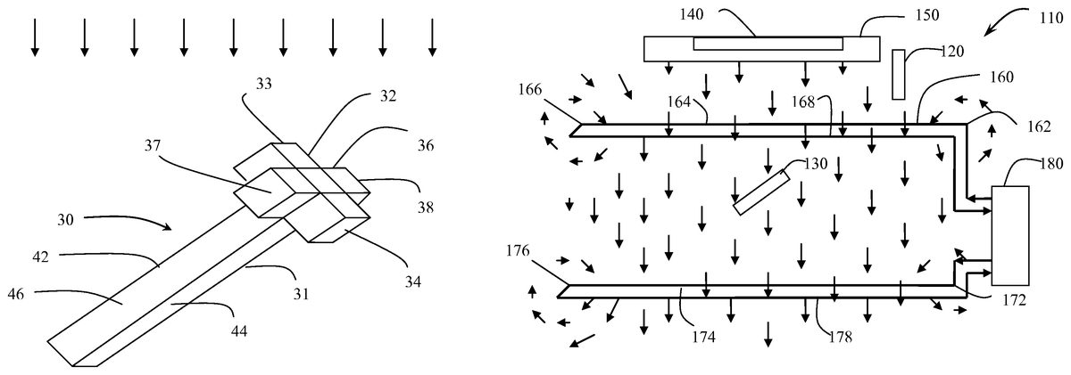
FIG. 6shows a top view of major components and magnetic field distribution in a second exemplary video game system110of the present invention.FIG. 7shows a front view of major components and magnetic field distribution in the embodiment ofFIG. 6. For purpose of demonstration, not all components inFIG. 6are shown inFIG. 7.
The main difference betweenFIG. 6andFIG. 3is that inFIG. 6, a steady DC current is generated by the current generator180so that there is a steady magnetic field within the wire loops160,170. Referring toFIGS. 6 and 7, the video game system110has a console120, a remote controller130, a sensor bar140, a video display150, a plurality of electrical wires160,170, and a DC current generator180.
The console120has a built-in microprocessor to execute software programs that stored in a disk and can be read by a disk drive of the console120. The console120is electronically coupled to the sensor bar140which contains a plurality of LEDs. The console120is also electronically coupled to the video display150. Typically, the sensor bar140is placed on top of the display without movement. When there is a movement between the remote controller130and the sensor bar140, the video game system110detects and reflects the movement by showing that movement on the video display150. The video game system110also makes a reaction based on the algorithm stored in the console120and shows that on the display150accordingly.
The remote controller130is the primary controller for the console120. The remote controller130has built-in accelerometers and gyroscopes. When the remote controller130is using with the LEDs within the sensor bar140, the infrared detection is able to sense its position in 3D space. Users control the game by using physical gestures as well as pressing buttons. The remote controller130is able to sense its motions including: tilting and rotation up and down, tilting and rotation left and right, rotation along the main axis (as with a screwdriver), acceleration up and down, acceleration left and right, and acceleration toward and away from the sensor bar140, or the video display150if the sensor bar140is placed near the display150.
In the embodiment ofFIGS. 6 and 7, two wires160,170are set up around the playing environment with a first wire160set up on the front side and a second wire170set up on the rear side. In other words, the first wire160is located between the video display150and the remote controller130while the remote controller130is located between the first wire160and the second wire170.
The first wire160can have four segments that a first segment162is generally extended vertically from the ground to a position that is higher than the height of the player's hand when his or her arm is raised. A second segment164is generally extended horizontally from the top-right side of the player to the top-left side of the player. The second segment164can be fixed on its position by hangers. Alternatively, the second segment164can be fixed to the ceiling of the room where the video game system110is set up. A third segment166is extended generally vertically from where the second segment164ends to the ground. A fourth segment168goes horizontally and can be placed on the ground.
The second wire170can have a similar setting as the first wire160. The second wire170also has four segments172,174,176,178that placed around the playing environment. The second wire170is placed in parallel with the first wire160so that the distance between the first wire160and the second wire170is about the same between each corresponding segments. AlthoughFIG. 7is a front view and the wires160,170are shown in skew. Especially, the fourth segments168,178can be both placed on the ground. The way it shows that segment168is higher than wire178is just for demonstration purpose.
In the embodiment ofFIGS. 6-7, the wires160,170are set up as a square and the distance between the two wires is about one half of the side of the square. For example, assuming that the height of the first segments162is two meters, it is preferred that all other segments164,166,168,172,174,176,178are also about two meters and the distance between the first wire160and the second wire170is about one meter.
In another embodiment, the first wire160and the second wire170can each be shaped as a circle. In that case, it is preferred that the first wire160and the second wire170have the same radius and the distance between the first wire160and the second wire170is about the same as the radius of the circles.
The current generator180has input ports and output ports. The first segment162of the first wire160is electrically coupled to one of the output ports of the current generator180and the fourth segment168of the first wire160is electrically coupled to one of the input ports of the current generator180. Similarly, the first segment172of the second wire170is electrically coupled to one of the output ports of the current generator180and the fourth segment178of the second wire170is electrically coupled to one of the input ports of the current generator180.
FIG. 6also shows a magnetic field distribution when steady DC electrical currents are applied to wires160,170by the current generator180whileFIG. 7shows the front view. The direction of DC electrical current flow is shown by arrows on wires160,170. In the first wire160, the steady electrical current is flow out from the current generator180to the first segment162, the second segment164, the third segment166, the fourth segment168, and then flow back to the current generator180. Similarly, in the second wire170, the impulse electrical current is flow out from the current generator180to the first segment172, the second segment174, the third segment176, the fourth segment178, and flow back to the current generator180.
Based on the Ampère-Maxwell equation, magnetic field can be produced by the steady electrical current as shown in the first term on the right hand side of the following equation:
curl(B)=μ0J+μ0ε0E/t
where J is the current density in amperes per square meter.
Arrows inFIG. 6represent magnetic field vectors in a plane bisecting the wires160,170. Note that the magnetic field is approximately uniform in between the wires160,170. InFIG. 7, the magnetic field vectors are point out from the page and denoted by double circles when they are within the loop of wires. The magnetic field vectors are point into the page and denoted by an x in circle when they are outside the loop of wires. Therefore, a steady magnetic field is generated by DC electrical currents.
FIG. 8shows an enlarged perspective view of the remote controller130ofFIGS. 6-7. The remote controller130has a handle131with two electromagnets132,136attached. The handle131has a front face142, a rear face144, a left face146and a right face148(not shown). The first electromagnet132has a first end133and a second end134while the second electromagnet136has a first end137and a second end138. The face of the first end133is parallel to the front face142. The face of the second end134is parallel to the rear face144. The face of the first end137is parallel to the left face146. The face of the second end138is parallel to the right face148. The orientation as well as the strength of the electromagnets132,136are stored in the console120by manufacturing.
When a user turns on the video game system110, the system110detects the position of the wires160,170. This detection can be made by placing tabs on the four corners of each wire160,170. Based on the placement of the wires160,170, the magnitude of magnetic field within the loop of wires160,170can be calculated when electrical currents are applied to wires160,170by the current generator180. Therefore, when a user is playing, the system110uses the acceleration and direction of the movement of the remote controller130to calculate the amount of force required and the timing to produce the impact reaction force. Once the desired impact reaction force is known, the system110creates a temporary magnet on the electromagnets132,136. The steady magnetic field thus generates a magnetic force emulating the impact reaction force on the electromagnets132,136of the remote controller130. The user therefore senses the impact reaction force when he or she strikes a ball.
Following is an example of a tennis game played by a right-handed player with the system110. When the player plays a forehand, the face of the first end133of the electromagnet132will first face the display150and then the face of the second end138will face the display150. Just before the face of the first end133is going to face the display150, the controller130set the first end133as the north pole with a desired magnitude based on the calculation previously described. The magnetic field generated by the wires160,170creates a magnetic force on the electromagnet132of the remote controller130to emulate the calculated impact reaction force. When the motion continues for a 90° turn and just before the face of the second end138of the electromagnet136is facing the display150, the controller130set the second end138of the electromagnet136as the north pole with a desired magnitude. The magnetic force created by magnetic field generated by the wires160,170acting on the electromagnet136of the remote controller130to emulate the calculated impact reaction force.
Therefore, when the hand of a player is moving around his or her body, the system110detects the swing and generates magnetic force two times within a 90° turn of the controller130. These two consecutive forces happened in a short period of time that the player may “feel” just like one hit of a tennis ball with an elastic tennis racquet.
When the player plays a backhand, the face of the second end134of the electromagnet132will first face the display150and then the face of the first end137of the electromagnet136will face the display150. Just before the face of the second end134is going to face the display50, the controller130set the second end134of the electromagnet132as the north pole with a desired magnitude based on a calculation described previously. The magnetic field generated by the wires160,170creates a magnetic force on the electromagnet132of the remote controller130to emulate the impact reaction force. When the motion continues for a 90° turn and just before the face of the first end137of the electromagnet136is facing the display150, the controller130set the first end137of the electromagnet136as the north pole with a desired magnitude so that a magnetic force is also applied on the electromagnet136of the remote controller130to emulate the impact reaction force.
In the exemplary embodiments described previously, although tennis is used as example, it is understandable that the exemplary embodiments also applied to other games such baseball, golf, or boxing.
Although the remote controller30,130shown previously is in a shape like a traditional TV remote control, it can be embedded in any shape as desired. For example, the remote controller30,130can be embedded in a boxer glove so that when a player is playing a box game with the system10,110, he or she can feel the impact reaction force when he or she strikes the opponent shown on the display50,150.
Various modifications and alternative embodiments such as would ordinarily occur to one skilled in the art to which the invention relates are also contemplated and included within the scopes of the invention described and claimed herein.
Claims
- A video game system comprising: a console having a microcontroller;a sensor bar electrically coupled to the console;a remote controller having at least a first electromagnet;and a magnetic field generator for generating a magnetic field to produce a desired force on the first electromagnet, wherein no part of the magnetic field generator is deposited within the remote controller, wherein the amount of the desired force is produced according to a relative movement between the remote controller and the sensor bar.
- The video game system of claim 1 further comprising a video display electrically coupled to the console.
- The video game system of claim 1 , wherein the amount of the desired force is calculated by a software program processed by the microcontroller.
- A method for a video game system for generating an emulated impact reaction force to a player comprising the steps of: producing a steady magnetic field by a magnetic field generator, wherein no part of the magnetic field generator is deposited within a remote controller;detecting a relative movement between the remote controller and a target object;predicting a timing, direction, and magnitude of a hit between the remote controller and the target object;calculating the direction and magnitude of an impact reaction force by the hit;and generating an electromagnet on the remote controller according to the relative movement to produce a force emulating the impact reaction force.
Disclaimer: Data collected from the USPTO and may be malformed, incomplete, and/or otherwise inaccurate.