U.S. Pat. No. 8,197,341
SUPPORT FOR A VIDEO GAME CONTROLLER
Issue DateJanuary 13, 2010
Illustrative Figure
Abstract
A support means for a controller for controlling a game which simulates a human activity involving hand and foot movements, for example the driving of a vehicle, the controller comprising a hand-operated device and a foot-operated device operable by a player of the game to cause the game to simulate such movements. The support means comprises a base (1) adapted to be supported on the floor or ground and having a platform (2) for mounting the hand-operated device (C1) of the controller which is pivotally mounted on a first member (15) which is mounted for rectilinear sliding movement on a second member (18) pivotally mounted on the base to facilitate angular, height and rectilinear adjustment of the device, and a platform (3) for mounting the foot-operated device which is mounted on a member (5) which is mounted for rectilinear sliding movement on the base to facilitate angular and rectilinear adjustment of the device.
Description
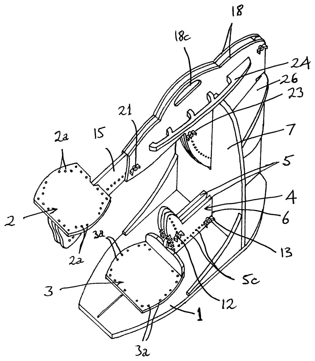
The support means illustrated in the drawings comprises a base1in the form of a flat panel having two mounting means2and3in the form of platforms for the hand-operated device and the foot-operated device, respectively, of a controller for controlling a game which simulates a human activity involving hand and foot movements, the hand-operated device and a foot-operated device being operable by a player of the game to cause the game to simulate such movements. By way of example,FIG. 2shows the support means fitted with a driving controller for controlling a game which simulates the driving of a car, the controller comprising a steering wheel unit C1mounted on the platform2and a pedal unit C2mounted on the platform3. The steering wheel unit comprises a base part supporting a steering wheel W which is turnable to steer the car in the game, and the pedal unit comprises a base part carrying two pedals P1and P2which a player depresses to accelerate and brake the car respectively. The controller is connected to a video games console or a personal computer diagrammatically illustrated at G inFIG. 3which is programmed to play the game. An electrical cable E1connects the steering wheel unit C1to the pedal unit C2and an electrical cable E2connects the steering wheel unit to the console or computer G. The platforms2and3are formed with holes2aand3a(FIG. 1) to receive bolts or screws or other means for securing base parts of the units C1and C2to them. In use, the base1is placed on the floor in front of the player who normally sits on a seat in the same position as he or she would be in if sitting in a real car (although the controller could be operated from a standing position). The seating position may vary depending, in particular, on whether the car in the game is a ...
The support means illustrated in the drawings comprises a base1in the form of a flat panel having two mounting means2and3in the form of platforms for the hand-operated device and the foot-operated device, respectively, of a controller for controlling a game which simulates a human activity involving hand and foot movements, the hand-operated device and a foot-operated device being operable by a player of the game to cause the game to simulate such movements.
By way of example,FIG. 2shows the support means fitted with a driving controller for controlling a game which simulates the driving of a car, the controller comprising a steering wheel unit C1mounted on the platform2and a pedal unit C2mounted on the platform3. The steering wheel unit comprises a base part supporting a steering wheel W which is turnable to steer the car in the game, and the pedal unit comprises a base part carrying two pedals P1and P2which a player depresses to accelerate and brake the car respectively.
The controller is connected to a video games console or a personal computer diagrammatically illustrated at G inFIG. 3which is programmed to play the game. An electrical cable E1connects the steering wheel unit C1to the pedal unit C2and an electrical cable E2connects the steering wheel unit to the console or computer G.
The platforms2and3are formed with holes2aand3a(FIG. 1) to receive bolts or screws or other means for securing base parts of the units C1and C2to them.
In use, the base1is placed on the floor in front of the player who normally sits on a seat in the same position as he or she would be in if sitting in a real car (although the controller could be operated from a standing position). The seating position may vary depending, in particular, on whether the car in the game is a road car or a racing car. The platforms are adjustable to enable the player to place the units C1and C2in the same positions as the steering wheel and pedals occupy in a real car. The player can therefore operate the steering wheel and the pedals in a realistic manner and the support means ensures that they do not move relative to the player.
The platform3is mounted on a support4comprising two parallel members5which are slidable towards and away from the player along the top of the base1, being guided by two slots6formed in a upright panel7attached to the base, a tongue8disposed between the slots and two pins9which project downwardly from the platform3and run in a groove10formed in the base (FIG. 5).
The platform3has a projecting part11formed with a hole11a(FIG. 5) which can be aligned with any one of a series of holes5aformed in the members5depending on the required angular position of the platform, a bolt then being inserted into the aligned holes and secured by a wing nut12(FIG. 1) to secure the platform in position. To provide further support for the platform in its adjusted position it has a lip3b(FIG. 3) which, prior to insertion of the bolt into the aligned holes, is engaged in one of a series of slots5bformed in the members5. The platform3can be set at the required distance from the player, taking into account the length of the player's legs, by sliding it along the base1until one of a series of holes5cformed in each member is aligned with a hole8aformed in the tongue8(FIG. 5), a bolt then being inserted into the aligned holes and secured by a wing nut13(FIG. 1).
The platform2is fixed to two parallel members14which straddle a member15and are pivotally mounted on it for turning about the axis of a bolt passing through aligned holes14aand15ain the respective members14and15, the bolt being secured by a wing nut16(FIG. 3). The member15is mounted for rectilinear sliding movement towards and away from the player in opposed channels17provided on two parallel members18(FIG. 5). These two members straddle and are mounted on an upright panel19which is attached to the top of the base1and the front side of the panel7, the members being located at opposite sides of the panel19in a slot7aformed in the panel7.
The members14have a series of holes14bany one of which can be aligned with a hole15bin the member15by pivoting the members14to set the required angular position of the platform2relative to the member15, a bolt being inserted into the aligned holes and secured by a wing nut20(FIG. 3).
The member15can be adjusted linearly relative to the members18by sliding it along the channels17to set the distance between the platform and the player, whereupon one of a series of holes15cin the member is brought into alignment with a pair of holes18ain the members18and a bolt is inserted into the aligned holes and secured by a wing nut21(FIG. 3) to lock the member15in place.
The members18are pivotally mounted on the upright panel19for turning about an axis formed by a bolt passing through aligned holes in the members and the panel, the bolt being secured by a wing nut22(FIG. 3). The angular position of the members18can be adjusted by pivoting them about the axis to adjust the height of the platform2, this bringing one of a series of holes18bin each member18into alignment with a hole19ain the panel. A bolt is then inserted into the aligned holes and secured by a wing nut23(FIG. 3).
The support means therefore has a wide range of possible adjustments for the platforms2and3to suit the player and the game being played. The support means can be used with any appropriate type of seat or chair and different types of hand- and foot-operated devices. The members18are formed with apertures18cto provide a handle by which the support means can be easily carried and moved from place to place. The support means can be disassembled for transport and storage.
Possible modifications include making parts of the support means, for example the base, collapsible and providing the base with lockable wheels or castors.
The support means may be made of any suitable material, for example plastics. The members18have fins24attached to their outer sides to give them additional rigidity. In order to give the platform2extra rigidity members25are attached to the platform and the members14. Also, a generally U-shaped member26straddles the members18and19to add further rigidity, its central part being attached to the front edge of the member19and its rear ends being attached to the member7. Notches18eformed in the members18(FIGS. 3 and 5) allow these members, and hence the steering wheel unit C1, to be positioned at low angles without the member26fouling the members18.
Instead of bolts with wing nuts other fixing means can be used. Also, the hand- and foot-operated devices could be secured to the platforms by other means.
The holes5a,5cin the members5, the holes14bin the members14, the holes15cin the member15and the holes18bin the members18may be provided with markings, for example numbers, so that each player can record for future use the positions in which the parts of the support are set to suit that player.
The support means is provided with a cable management system to hold the electrical cables of the controller and prevent them being yanked, crushed or otherwise damaged or becoming entangled when the support means is being adjusted and the devices C1and C2are being used. The two cables E1and E2running from the steering wheel unit C1to the pedal unit C2and the console or computer G are positioned at the respective outer sides of the members18where they are held by cable holders associated with the respective fins24. The cables lie in upwardly facing channels24aformed in the fins24and are held in position by cable fasteners. Each fin has five such fasteners comprising elastic elements27as shown inFIGS. 6 to 9. Each element27normally assumes a closed position to hold the relevant cable in the channel of the relevant fin as shown inFIG. 8, and can be pulled upwardly against the effect of its springiness as shown inFIG. 9to enable the cable to be inserted into and removed from the channel.
Referring toFIGS. 3 and 4, each cable E1, E2is securely attached to the relevant fin24at point A. An elongate elastic element28is attached to each fin at point B, passes loosely through holes24bformed in the underside of the fin and has its other end attached by a spring clip29to the relevant cable at point C. An elongate elastic element30is also secured by spring clips31to the cable E1at spaced intervals. The two cables are secured to the platform2by spring clips32and the cable E1is similarly secured to the platform3by a spring clip (not shown).
When setting up the support means for use, with the steering wheel and pedal units mounted on the platforms2and3and the electrical cables connected to the units, the platforms2and3are first pulled towards the user to the maximum possible extent as illustrated inFIG. 3. Then the electrical cables E1and E2are attached to the platform2by the spring clips32and to the fins24at point A so that they are taut between these clips and point A, the cables also being located in the channels24aof the fins and secured by the elements27. The cable E1is also attached to the platform3. The elastic elements28which are attached to the fins at point B are stretched and attached to the respective cables by the spring clips29at point C. The elastic element30is attached in a stretched condition to the cable E1by the spring clips31so that the cable is taut. As a result, when the platforms2and3are moved away from the user to the required positions to suit the user as illustrated inFIG. 4, the elastic elements28and30contract to hold the cables in neat loops.
Instead of the elastic elements27, other forms of spring-biased fasteners may be used to hold the cables in the channels24aof the fins24. Likewise, other forms of releasable spring-operated connectors may be used instead of the spring clips29,31and32.
If the support means is to be used with a games controller in which there are wireless connections between the steering wheel unit, the pedal unit and the video games console or computer, the cable management system may be omitted.
Claims
- A support device for a controller for controlling a game which simulates a human activity involving hand and foot movements, the controller comprising a hand-operated device and a foot-operated device operable by a player of the game to cause the game to simulate such movements, the support device comprising a base which is adapted to be supported on the floor or ground an upright support attached to the base and extending upwardly therefrom;a mounting for the hand-operated device of such a controller and a mounting for the foot operated device of the controller;the mounting for the hand-operated device being provided with a support comprising a member which has an end which carries the mounting and an end part remote from the mounting, said remote end part of the member being pivotally mounted to the upright support so as to permit pivoting about a horizontal axis and the end which carries the mounting being movable up and down by pivoting the member to adjust the height of the mounting.
- A support according to claim 1 wherein the support member for the mounting for the hand-operated device is slidable relative to the pivotally mounted end part thereof to adjust the distance between the ends of the support member.
- A support device as claimed in claim 1 wherein the support for the mounting for the hand-operated device is constructed to facilitate angular adjustment of the mounting relative to the said pivotally mounted member.
- A support device as claimed in claim 1 wherein the mounting for the foot-operated device is provided with a support constructed to facilitate rectilinear adjustment of the said mounting relative to the base towards and away from the position to be occupied by a player.
- A support device as claimed in claim 1 wherein the mounting for the foot-operated device is constructed to facilitate adjustment of the angular position of the mounting relative to the base.
- A support device as claimed in claim 1 wherein the upright support comprises an upright panel attached to the base and to one side of a further panel which is also attached to the base.
- A support device as claimed in claim 1 wherein the mounting for the hand-operated device is in the form of a platform which is mounted on the support member for angular adjustment relative to the support member, and is mounted relative to the said pivotally mounted end part for rectilinear sliding movement relative to the support member, a securing structure being provided for securing the platform, the said further member and the pivotally mounted member in a plurality of different positions.
- A support device as claimed in claim 1 wherein the mounting for the foot-operated device is in the form of a platform which is mounted on a member for angular adjustment relative to the member, this member being mounted on the base for rectilinear sliding movement relative to the member, a securing structure being provided for securing the platform and the said member in a plurality of different positions.
- A support device as claimed in claim 6 wherein the mounting for the hand-operated device is in the form of a platform which is mounted on a member for angular adjustment relative to the member, this member being mounted on the said pivotally mounted member for rectilinear sliding movement relative to the member, a securing structure being provided for securing the platform, the said further member and the pivotally mounted member in a plurality of different positions, and wherein the mounting for the foot-operated device is in the form of a platform which is mounted on a member for angular adjustment relative to the member, this member being mounted on the base for rectilinear sliding movement relative to the base, a securing structure being provided for securing the platform and the said member in a plurality of different positions and wherein the pivotally mounted member carrying the mounting for the hand-operated device is located in a slot in the said further panel and the rectilinearly slidable member carrying the mounting means for the foot-operated device is guided by a slot in the said further panel.
- A support device as claimed in claim 1 which is provided with an electrical cable management system.
- A support device as claimed in claim 10 wherein the said system comprises cable holders provided on the support and having fasteners for holding cables in the holders.
- A support device as claimed in claim 10 wherein the said system comprises elongate elastic elements having connectors for attaching them to cables.
- A driving controller for controlling a game which simulates the driving of a car, the controller comprising a steering wheel and a pedal unit, each of which is supported by a mounting, the steering wheel being mounted on a steering wheel mounting which is provided with a steering wheel support comprising a member, having two ends, one end of which is mounted for pivoting about a horizontal axis on an upright support attached to a base, and the other end of which carries the steering wheel mounting and is free to move up and down by pivoting the member to adjust the height of the said mounting.
- A driving controller for controlling a game which simulates the driving of a car, as claimed in claim 13 , wherein the pedal unit is mounted on a platform which is mounted on a pedal support, which is constructed to facilitate rectilinear adjustment of said pedal mounting relative to the base of the pedal support, towards and away from a position to be occupied by a player of the game.
Disclaimer: Data collected from the USPTO and may be malformed, incomplete, and/or otherwise inaccurate.