U.S. Pat. No. 8,192,284
METHOD, STORAGE MEDIUM, AND APPARATUS FOR GENERATING IMAGE OF VIRTUAL SPACE
AssigneeBandai Namco Entertainment Inc
Issue DateDecember 9, 2009
Illustrative Figure
Abstract
A method for executing a game having a motif of rolling an object combined with another object with which the object is contacted, on a surface of the object, and growing large like a snowball. The method has: controlling a rotation and a movement of a first object as an operated object, in a virtual space; combining one of a plurality of second objects, with which the operated object is contacted, around a contact position of the operated object, at which the operated object is contacted with the one of the second objects, when the operated object is contacted with the one of the second objects; and determining the operated object with which the one of the second objects is combined, and the one of the second objects, when the one of the second objects is combined with the operated object, as an operated object, newly.
Description
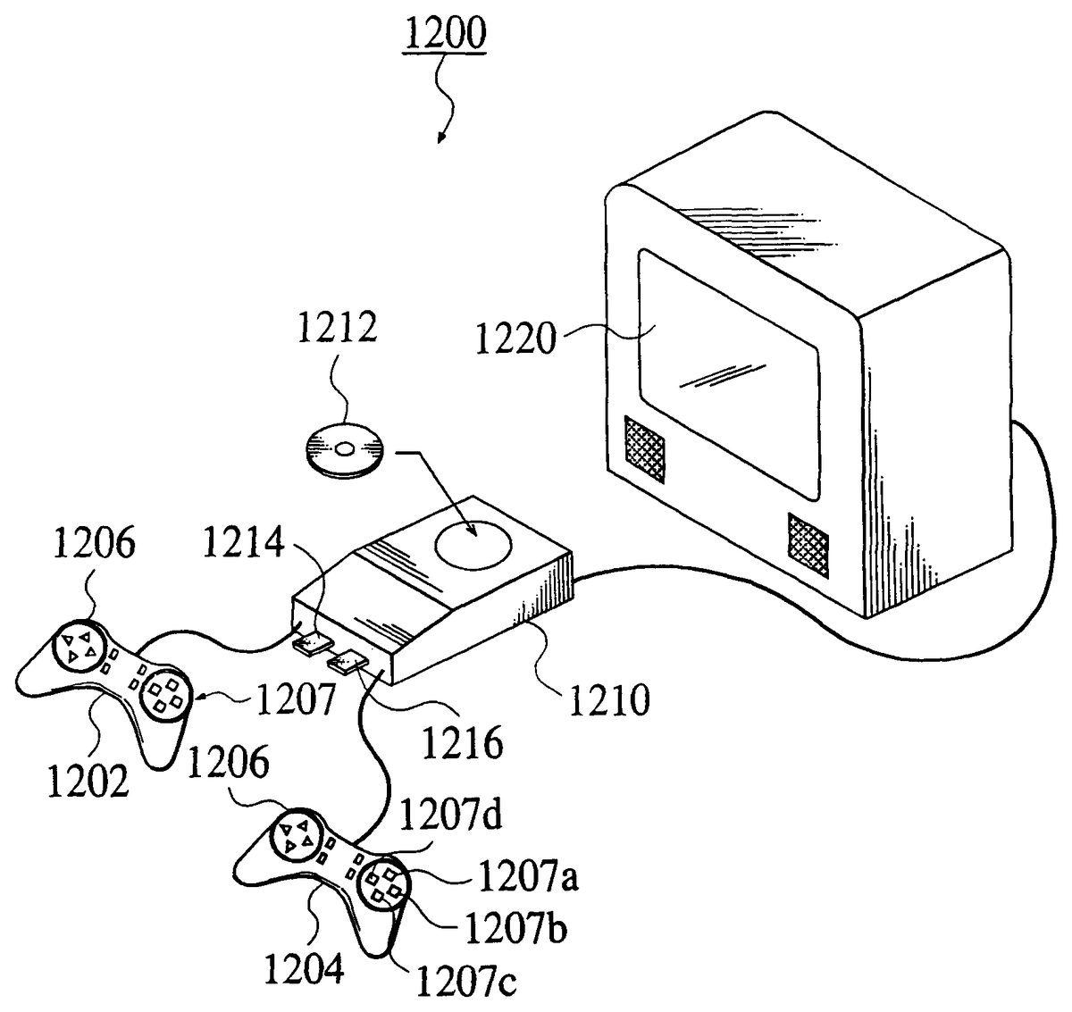
PREFERRED EMBODIMENTS OF THE INVENTION [First Embodiment] Hereinafter, a first embodiment to which the present invention is applied will be explained with reference toFIGS. 1 to 14C, in detail. According to the first embodiment, “a large ball rolling game” will be explained as an example, the large ball rolling game for combining objects other than a ball object as an operated object with a surface of the ball object like a snowball, and competing for the size of the ball object enlarged within a limited time. The present invention is not limited to the large ball rolling game. For example, it is possible to apply the present invention to a game having a motif of rolling an object, regardless of a character or a story of the game. [Explanation of Structure] First, a structure according to the first embodiment, will be explained. FIG. 1is a view showing an example of an external appearance of a consumer game apparatus1200to which the present invention is applied. As shown inFIG. 1, the consumer game apparatus1200comprises game controllers1202and1204, and an apparatus body1210. The consumer game apparatus1200is connected to a display1220. Game data required to execute a game, such as a game program, game data or the like, are stored in a CD-ROM1212, an IC memory1214, a memory card1216or the like, as a storage medium which can be attached to and detached from the apparatus body1210. The apparatus body1210executes various game processing, and makes the display1220display game screens thereon, on the basis of the game data read out of the storage medium, and an operation signal inputted through the controller1202or1204. The player enjoys playing the game by operating a cross key, levers, various types of buttons or the like, provided for the game controller1202or1204, and controlling the movement of the ball object, with watching the ...
PREFERRED EMBODIMENTS OF THE INVENTION
[First Embodiment]
Hereinafter, a first embodiment to which the present invention is applied will be explained with reference toFIGS. 1 to 14C, in detail. According to the first embodiment, “a large ball rolling game” will be explained as an example, the large ball rolling game for combining objects other than a ball object as an operated object with a surface of the ball object like a snowball, and competing for the size of the ball object enlarged within a limited time.
The present invention is not limited to the large ball rolling game. For example, it is possible to apply the present invention to a game having a motif of rolling an object, regardless of a character or a story of the game.
[Explanation of Structure]
First, a structure according to the first embodiment, will be explained.
FIG. 1is a view showing an example of an external appearance of a consumer game apparatus1200to which the present invention is applied. As shown inFIG. 1, the consumer game apparatus1200comprises game controllers1202and1204, and an apparatus body1210. The consumer game apparatus1200is connected to a display1220.
Game data required to execute a game, such as a game program, game data or the like, are stored in a CD-ROM1212, an IC memory1214, a memory card1216or the like, as a storage medium which can be attached to and detached from the apparatus body1210.
The apparatus body1210executes various game processing, and makes the display1220display game screens thereon, on the basis of the game data read out of the storage medium, and an operation signal inputted through the controller1202or1204.
The player enjoys playing the game by operating a cross key, levers, various types of buttons or the like, provided for the game controller1202or1204, and controlling the movement of the ball object, with watching the game screen displayed on the display1220.
The game controller1202or1204is provided with two systems of input means for inputting various directions. In an example shown inFIG. 1, a cross key1206and a button group1207having buttons arranged in a cross, correspond to the two systems of input means. That is, one system is input means for inputting forward, backward, rightward and leftward directions (or upward, downward, rightward and leftward directions) with the cross key1206. The other system is input means for inputting forward, backward, rightward and leftward directions with the button group1207(the forward direction with a button1207a, the rightward direction with a button1207b, the backward direction with a button1207c, and the leftward direction with a button1207d). Each of the cross key1206and the button group1207may have a structure of inputting directions with a lever such as an analogue stick or the like.
[Explanation of Game Contents]
FIGS. 2A and 2Bare views showing exemplary game screens generated by the consumer game apparatus1200. The game screen is displayed, for example, as a 3DCG (three-dimensional computer graphics) image based on polygons of a game space in which objects are provide, viewed from a predetermined view point (a virtual camera).
According to the first embodiment, the player controls a character C, so that the character C walks with rolling a strange ball B with a surface of which objects is combined, when the ball B is contacted with the objects. The ball B corresponds to the operated object, although it is apparently through the character C. The direction in which the character C rolls the ball B is inputted through the cross key1206and the button group1207of the controller1202or1204.
The player makes the ball B come into collision with objects E provided for the whole town, well, combines the objects E with the surface of the ball B, and enlarges the ball B like the snowball. Although the ball B can be combined with a smaller object than a predetermined size against the size of the ball B, the ball B cannot be combined with a larger object than the predetermined size. For example, inFIG. 2A, because walls E4and E5, a utility pole E6, and a track E7are larger than the ball B, the ball B cannot be combined with any of them.
The object E which cannot be combined with the ball B affects the ball B as an obstacle. For example, when the ball B comes into collision with the object E which affects the ball B as the obstacle, the object E which is previously combined with the ball B, is separated from the ball B by the collision, or the ball B is deformed by the force of the collision and the rotation of the ball B is affected. Accordingly, the player ascertains the object E which will be not able to be combined with the ball B, controls the ball B so as to dodge the object E well, and enlarges the ball B.
FIGS. 3A,3B and3C are views for explaining examples of methods for operating the ball B. InFIGS. 3A to 3C, a key or a button which is pushed is shown in black. The cross key1206and the button group1207as two systems of direction input means provided for the game controller1202or1204, correspond to means for inputting rotations of a left hemisphere and a right hemisphere, respectively. Therefore, the direction of rolling the ball B is determined according to the difference between the rotation of the left hemisphere and the rotation of the right hemisphere which are inputted through the cross key1206and the button group1207. That is, the direction of rolling the ball B is determined according to the difference between the inputted operation signal of the right hemisphere and the inputted operation signal of the left hemisphere.
For example, in case of moving the ball B on the straight, as shown inFIG. 3A, the player pushes the upward direction of the cross key1206and the button1207athe approximately same. In case of curving the ball B, the player discriminates between the inputted quantity of the cross key1206and the inputted quantity of the button group1207. As shown inFIG. 3B, when the player pushes only the upward direction of the cross key1206, because the rotation of the left hemisphere is more than the rotation of the right hemisphere, the direction of the ball B is changed to the rightward, according to the difference between the torques. Further, as shown inFIG. 3C, when the player pushes the upward direction of the cross key1206and the button1207c, the ball B is rotated around the center, so that the direction of the ball B is changed without changing the central position.
FIG. 4is a conceptual view showing an example of a structure of the game stage. According to the first embodiment, the game stage consists of stages ST1to ST3. The size of the object E provided for the stage becomes large as the stage progresses. For example, the object E of the size such as an empty can, a baseball ball, a tennis racket, a TV or the like, is provided for the stage ST1. Further, the object E of the size such as a bench, a refrigerator, a mailbox, a bicycle, a tax or the like, is provided for the stage ST2. Furthermore, the object E of the size such as a track, a bus, a train, a house or the like, is provided for the stage ST3. More specifically, the maximum value of the size of the object E is determined for every stage. Therefore, smaller various objects E than the maximum value are provided for every stage.
The stages STs are divided with a slope SL. Therefore, when the ball B goes over the slope SL, the ball B can progress to the next stage. That is, the maximum arrival speed or the acceleration of the ball B becomes high, according to the size of the ball B. Therefore, when the ball B is combined with the object E and enlarged efficiently, the ball B goes over the slop SL and progresses to the next stage by the force.
The ball B is firstly combined with the object E of the size such as an empty can or the like. With the ball B becomes large, the ball B is combined with the object E of the size such as a bicycle, a mailbox, a bus or the like. Finally, the ball B is combined with the object E of the size such as a house, a utility pole or the like, destroys the town, and becomes large. Lastly, when the player stuffs a crater ST4of MT. Fuji, with the enlarged ball B, and prevents an eruption, the player clears the game.
The player can enjoy making the character dodge the obstacle and run through the stage, like the conventional action adventure game. Further, the player can take enjoyment which the player cannot find conventionally, that is, the player can enjoy making full use of the operation technique of rolling the ball according to the difference between the right and left rotations, and feeling the ball destroying the object, which happens in the unusual state and which is filled with jokes.
[Explanation of Functional Block]
Next, the functional block realizable of the first embodiment, will be explained, as follows.
FIGS. 5A and 5Bare block diagrams showing examples of functional structures according to the first embodiment. As shown inFIGS. 5A and 5B, the functional block composing the first embodiment, comprises an operation unit10through which the player inputs the operation, a processing unit20for processing the operation for controlling the apparatus or the game, a display unit30for displaying the game screen thereon, and a storage unit50for storing the program, data or the like therein.
The operation unit10corresponds to the game controller1202or1204shown inFIG. 1. The player inputs the operation through the operation unit10. The operation signal outputted from the operation unit10is transmitted to the processing unit20.
The processing unit20performs various operating processing such as a processing for controlling the whole game apparatus, a processing for instructing each functional block of the game apparatus, a processing for operating the game or the like. The function of the processing unit20can be realized by a hardware such as a CPU (the CISC type, the RISC type), the DSP, the ASIC (the gate array or the like) or the like, a predetermined program, data or the like. The processing unit20comprises a game operating unit22for performing the processing for operating the game, and an image generating unit240for generating image data based on various types data obtained by the processing performed by the game operating unit22.
The game operating unit22performs various game processing on the basis of the operation signal inputted through the operation unit10, programs, data or the like read out of the storage unit50. The game processing includes, for example, a processing for calculating coordinates of the position, the speed or the like, of the object as the object moves, a processing for determining the collision of the object, a processing for providing the object in the object space, a processing for selecting mapping information of the object, a processing for obtaining the result (score) of the game, and so on.
Further, the game operating unit22comprises a rotation control unit221, a combination determination unit222, an object combining unit223, a traveling ability determination unit224, a viewpoint determination unit225and an object deformation unit226.
The rotation control unit221determines the direction in which the ball B moves, the quantity by which the ball B moves, and the rotation of the ball B. More specifically, for example, the cross key1206shown inFIG. 1, is related to the input of the left hemisphere rotation of the ball B, and the button group1207shown inFIG. 1, is related to the input of the right hemisphere rotation of the ball B. Therefore, the rotation control unit221compounds the speeds of the right and left hemispheres, determines the speed of the ball B, and calculates the quantity by which the ball B moves, for every frame. When determining the moving direction and the moving quantity, the rotation control unit221determines the quantity by which the ball B rotates, so that the moving direction and the moving quantity are caused by the rotation.
The combination determination unit222compares the parameter of the ball B with the parameter of the size of the object E, and determines whether the object E can be combined with the ball B or not, for every object E. More specifically, for example, the combination determination unit222searches the object E provided within the predetermined distance from the ball B, and considers the object E as the object of the determination. Then, when the combination determination unit222determines that the size of the object E is smaller than 20% of the radius of the ball B, the object E can be combined with the ball B. In case the object E is a hierarchical model consisting of a plurality of nodes (elements), the combination determination unit222performs the processing for every note.
The object combining unit223calculates the contact position at which the object E and the ball B are contacted with each other, on the basis of displayed models of object E and the ball B, and combines the object E with the ball B at the contact position, in case it has been determined that the ball B comes into collision with the object E, and the object E is determined to be combined with the ball B. By contraries, the object combining unit223separates the object E which has been combined with the ball B, from the ball B, in case it has been determined that although the ball B comes into collision with the object E, the object E cannot be combined with the ball B because the size of the object E.
More specifically, the object combining unit223can combine the object E with the ball B, and separate the object E from the ball B, by defining the hierarchical relation between the model of the ball B and the model of the object E. Therefore, when the ball B (operated object) comes into collision with or is combined with the object E, the hierarchical relation is renewed. Accordingly, the ball B with which the object E is combined, is processed as a new operated object.
Further, the object combining unit223enlarges/reduces the collision determined model of the ball B, according as the object E is combined with/separated from the ball B. For example, in case the object E is combined with the ball B, the object combining unit223enlarges the collision determined model of the ball B to the same size as the total volume of the volume of the ball B and the volume of the object E. By contraries, in case the object E which has been combined with the ball B is separated from the ball B, the object combining unit223reduces the collision determined model of the ball B by the volume of the object E separated from the ball B.
The traveling ability determination unit224changes the traveling ability parameter of the ball B according to the size of the ball B. The traveling ability parameter may include, for example, not only the maximum arrival speed, the acceleration and so on, but also the inertia and so on, as the occasion may demand. According to the first embodiment, the quantity of change in the parameter, is determined so as to keep the constant relation between the quantity of operating the ball B with the game controller1202or1204and the quantity of moving the ball B on the game screen. As a result, it is possible to realize the game the player can always stably operate and play without feeling stress, regardless of the size or the weight of the ball B.
The viewpoint determination unit225changes the condition of the viewpoint according to the size of the ball B, and determines whether the extremely small object displayed on the game screen, is displayed or not, according to the condition of the viewpoint. According to the first embodiment, the viewpoint determination unit225changes the condition of the viewpoint to the predetermined condition, gradually, even when the size of the ball B gets to the predetermined size. Then, the viewpoint determination unit225determines the condition (the angle, the view angle or the like) of the viewpoint, so that the rate of the ball B in the game screen just after changing the condition of the viewpoint is approximately the same as one before changing the condition of the viewpoint.
For example,FIGS. 13A to 13Eare views for explaining the concept of changing the viewpoint according to the first embodiment. As shown inFIG. 13A, according to the first embodiment, the viewpoint (virtual camera) CM is provided behind the character C which pushes the ball B. Further, the position at which the viewpoint is provided is changed, and the viewpoint is changed (CM1-CM2- . . . ), according as the size of the ball B is changed (B1-B2-B3- . . . ).
More specifically, for example,FIGS. 13B,13C,13D and13E show examples of the game screens.FIGS. 13B and 13Care game screens based on the viewpoint CM1. The ball B becomes large from the ball B1to the ball B2, as the game progresses. Therefore, as shown in FIG. C, because the rate of the ball B in the game screen increases, it becomes hard to see the forward. Accordingly, the viewpoint is changed from the viewpoint CM1to the viewpoint CM2.FIGS. 13D and 13Eare game screens based on the viewpoint CM2. Herein, the ball B is displayed on the screen shown inFIG. 13Djust after the viewpoint is changed from the viewpoint CM1to the viewpoint CM2, so that the size of the ball B displayed on the screen shown inFIG. 13D, is approximately the same as the size of the ball B displayed on the screen shown inFIG. 13B.
The object deformation unit226changes the displayed model of the ball B according to the relative momentum “mv” of the ball B and the object E, in case the ball B comes into collision with the object E (obstacle) which cannot be combined with the ball B.
More specifically, for example, the object deformation unit226deforms the displayed model of the ball B according to the known method such as the FFD (Free Form Deformation) or the like. Because the object E which has been combined with the ball B and the displayed model of the ball B have the hierarchal relation, and the object E is deformed as the ball B is deformed, the whole ball B is deformed. Although the ball B is deformed plastically according to the first embodiment, the ball B may be deformed elastically according to the game story or the condition of the ball B. Further, the quantity of the deformation of the ball B may be determined according to the characteristic of the game, as the occasion may demand.
The image generating unit24consists of a hardware such as a CPU, the DSP, an image generation exclusive IC, a memory or the like. The image generating unit24generates image signals on the basis of the instruction signal, various types coordinate data or the like, outputted from the game operating unit22. Further, for example, the image generating unit24performs a composition processing for changing the a value of the object E, and semitransparently displaying the object, or the like.
The display unit30is a device for displaying the game screen on the basis of the image signals generated by the image generating unit24, thereon. The display unit30corresponds to the display1220shown inFIG. 1. The display unit30can be realized by a hardware such as a CRT, a LCD, an ELD, a PDP, a HMD or the like.
The storage unit50stores a program, data or the like, for executing the control of the whole apparatus. For example, the storage unit50can be realized by a hardware such as a CD-ROM, a game cassette, an IC card, a MD, the FD (registered mark), a DVD, an IC memory, a hard disc or the like. The storage unit50stores game data52including a program for executing various processing for the game, and data such as determined values required to execute the program.
As the program, the game data52includes a rotation control program521for making the rotation control unit221function, a combination determination program522for making the combination determination unit222function, an object combining program523for making the object combining unit223function, a traveling ability determination program524for making the traveling ability determination unit224function, a viewpoint determination program525for making the viewpoint determination unit225function, and an object deformation program526for making the object deformation unit226function.
Further, as the data, the game data52includes viewpoint data53, stage data54, ball data60and object data70for storing data required to determine whether the ball B and the object E are displayed or not, or whether the ball B comes into collision with the object E.
The viewpoint data53stores a viewpoint determined value531for storing determined values such as a position, a view angle or the like, of the present viewpoint, and a viewpoint determined table532. The viewpoint determined table532, as shown inFIG. 6, stores a ball size range532-1of the ball B, a proper determined value532-2storing determined values such as a position, a view angle or the like, of the viewpoint related to the ball size range532-1, and a display level532-3.
The stage data54stores, for example, structure data541, objects list data542of the objects E provided in each stage, a clear condition or the like.
The structure data541stores data for providing the space of the stage, for example, data such as a position or an inclined angle of the slop SL.
The objects list data542registers the object E which is not larger than the size which is previously determined for every stage. More specifically, the object list data542registers, for example, the object E (for example, the objects E1to E3shown inFIG. 2) which is determined to be the size so as to be combined with the ball B of the size required to clear the stage, and the object E (for example, the objects E4to E12shown inFIG. 2) which is determined to be the size so as to function as the obstacle in the stage. Because the object E is provided in the object space, on the basis of the objects list data542, it is possible to adjust the size of the object E which can be combined with the ball B, for every stage.
The clear condition is that the ball B goes over the slop SL at a predetermined slope, the slope SL dividing the stages STS, as shown inFIG. 4, according to the first embodiment. However, for example, the clear condition may be the number of specific items (for example, 500 empty cans) which are combined with the ball B, of items which are provided in each stage ST. Therefore, the clear condition may be determined as the occasion may demand.
The ball data60includes ball displayed model data61, ball hierarchy data62, ball collision determined model data63, a ball parameter64, and combinations list data65.
The ball displayed model data61stores modeling data of the original model as an initial state any object E is not combined with the ball B.
The ball hierarchy data62stores data of the hierarchical structure consisting of the original model of the ball B as the parent node (element) and the object E which is combined with the ball B as the child node (element). According to the first embodiment, the ball hierarchy data62stores, for example, the identification number of the object E, the coordinates of the position at which the object E is combined with the ball B, and the posture angle data of the object E. However, the ball hierarchy data62may store contents of data selected as the occasion may demand.
The ball collision determined model data63stores modeling data of the ball collision determined model of the ball B. According to the embodiment, the collision determined model is defined as a so-called bounding volume.
The ball parameter64stores a state and various determined data of the present ball B. More specifically, for example, the ball parameter64includes a speed, an acceleration, position coordinates, a rotation angle, a minimum circular radius, a maximum arrival speed641, an acceleration642, a radius643and a volume644. The contents of data stored in the ball parameter64is not limited to the above-described data. The contents of data stored in the ball parameter64may be determined as the occasion may demand.
The combinations list data65stores the identification number651and the combination position coordinates652of the object E, in the order of the combination with the ball B.
The object data70store data on the display or the collision determination of each of all objects other than the ball B, provided in the game space, for every object E. The object data70further stores data on the displayed form or the composition such as the texture, the value of the object E, or the like.
Further, the object data70include object hierarchy data71, object displayed model data72, object collision determined model data73, combination determination data74, an object parameter75, and display determination data76.
The object hierarchy data71store hierarchy data of the model of the object E. For example, the object hierarchy data71stores a signal M consisting a signal pole M1as the parent node, and a signal head M2as the child node, as the hierarchical model, as shown inFIGS. 14A to 14C(a broken line shows a bounding volume of each node, inFIG. 14A).
The object displayed model data72store modeling data of the displayed model of each of nodes composing the object E.
The object collision determined model data73store modeling data of the collision determined model of each of nodes composing the object E. According to the first embodiment, the collision determined model is a so-called bounding volume (for example, shown in the broken line inFIG. 14A). However, the collision determined model may be determined as the occasion may demand.
The combination determination data74store data showing whether the object E can be combined with the ball B or not, for example, “1” showing that the object E can be combined with the ball B or “0” showing that the object E cannot be combined with the ball B. The combination determination data74is determined when the combination determination unit222compares the size of the ball B with the size of the node.
The object parameter75stores data on the size of the node. The object parameter75includes, for example, data on a speed, an acceleration, position coordinates, a rotation angle, a maximum arrival speed, a representative size751, a volume752or the like, like the ball parameter64. Further, the object parameter75may include data on a weight, a temperature, an attribute or the like, as the occasion may demand.
The display determination data76store, for example, an object display level determined value761related to the display level532-3of the viewpoint data53, and a display flag762for specifying whether the object E is displayed and determined to come into collision with the ball, or not, as shown inFIG. 7.
As shown inFIG. 7, the object display level determined value761shows that the object is displayed while the display level is not larger than the determined value. Therefore, even when the viewpoint is changed, the object display level determined value761is compared with the display level532-3of the viewpoint data53. In case shown inFIG. 7, because it is determined that the object is not displayed at the viewpoint having the display level532-3which is equal to or larger than “3”, “0” is stored in the display flag762.
Therefore, for example, in case the range displayed on the game screen is approximately the field of vision of a human, the object E of the size of the empty can is determined to be displayed. However, in case the range displayed on the game screen is extended and approximately a bird's eye view, the object E of the size of the empty can is determined to be not displayed. Accordingly, it is possible to keep the game screen which can be seen easily, and to reduce the processing load.
[Explanation of Flow]
Next, the detailed flow of the processing according to the first embodiment, will be explained with reference toFIGS. 8A to 11. Because a processing for determining the collision, a processing for calculating coordinates of the position at which the models are contacted with each other, a movement operating processing for determining the position, the speed, the acceleration, and the rotation of the object, or the like has been known, it is omitted to explain the above-described processing.
FIGS. 8A and 8Bare flow charts for explaining the flow of the game processing.
As shown inFIG. 8A, firstly, the game operating unit22determines the size or the position of the ball B, the viewpoint, the stage, in default, and starts the game (Step S102).
When the game operating unit22starts the game, and receives the operation for moving the ball, inputted through the operation unit10(Step S104), the rotation control unit221executes the rotation control processing, and calculates the rotation of the ball B on the basis of the operation signal inputted through the operation unit10(Step S106).
[Rotation Control Processing]
FIG. 9is a flow chart for explaining the flow of the rotation control processing. According to the rotation control processing, firstly, the rotation control unit221refers the ball parameter64, and obtains data on the present speed “Vh”, the position, the maximum arrival speed “Vmax”, the acceleration or the like (Step S202).
Then, the rotation control unit221calculates the speed “Vl” of the left hemisphere of the ball B on the basis of the input through the cross key1206, and the speed “Vr” of the right hemisphere of the ball B on the basis of the input through the button group1207(Step S204). When calculating the speeds “Vl” and “Vr” of the left and right hemispheres, the rotation control unit221compounds the speeds “Vr” and “Vl”, and obtains the total speed “Vh” of the ball B (Step S206).
When the rotation control unit221determines that the speed “Vh” is equal to or higher than the maximum arrival speed641“Vmax” (Vh≧Vmax) (Step S208; YES), the rotation control unit221determines the speed “Vh” to the maximum arrival speed “Vmax” (Vh=Vmax) (Step S210).
When obtaining the speed “Vh”, the rotation control unit221determines coordinates of the position to which the ball B moves (Step S212). Then, the rotation control unit221calculates the number of rotations of the ball B, which causes the ball B to move to the position in the direction of the speed “Vh”, that is, the rotation angle (Step S214). Thereafter, when the rotation control unit221renews the ball parameter64(Step S216), and ends the rotation control processing, the game processing comes back to the flow shown inFIG. 8A.
Coming back to the flow shown inFIG. 8A, the game operating unit22operates the movement of the object E (for example, a car, a human, an animal) other than the ball B, which moves by itself (Step S108).
When the game operating unit22determines the positions of the ball B and the object E, the combination determination unit222executes the combination determination processing, and determines whether the object E included within the predetermined range from the ball B, can be combined with the ball B or not (Step S110).
[Combination Determination Processing]
FIG. 10is a flow chart for explaining the flow of the combination determination processing.
As shown inFIG. 10, firstly, the combination determination unit222searches the object E which is within the predetermined radius from the ball B (Step S302). For example,FIG. 15is a view showing a state the ball B moving on the road surrounded with the walls E4, E5and E8, is viewed from the right above position. In case shown inFIG. 15, the objects E1to E3are objects of the combination determination.
Then, the combination determination unit222compares the object parameter75of the searched out object E with the ball parameter64, that is, compares the representative size751(R2) of the object E with the radius643(R1) of the ball B, and determines the size relation between the object E and the ball B (Step S304).
When the combination determination unit222determines that the representative size751(R2) of the object E is equal to or smaller than 20% of the radius643(R1) (R1×0.2≧R2) (Step S306; YES), the combination determination unit222determines that the object E can be combined with the ball B, and stores “1” in the combination determination data74of the object E (Step S308). On the other hand, when the combination determination unit222determines that the representative size751(R2) of the object E is not equal to or smaller than 20% of the radius643(R1) (R1×0.2determined value) (Step S126; YES), that is, the collision is hard, the object combining unit223executes the combination release processing, separates the object E which has been combined with the ball B from the ball B, and recreates the state the objects drops from the ball B by the collision (Step S128).
[Combination Release Processing]
FIG. 12is a flow chart for explaining the flow of the combination release processing. According to the combination release processing, firstly, the object combining unit223determines the number “n” of objects to be separated from the ball B by releasing the hierarchy according to the relative momentum “mv” (Step S502). Then, the object combining unit223determines the angle coordinate value “ ” in the pole coordinate system, showing the range for selecting the object to be separated, according to the relative momentum “mv” (Step S504). The number “n” of objects and the angle “θ” are determined as the occasion may demand, in consideration of the limit.
Then, the object combining unit223determines the coordinates of the contact position “H” at which the object E is contacted with the ball B, on the basis of the ball displayed model data61of the ball B and the object displayed model data72of the object E which comes into collision with the ball B (Step S506).
When determining the contact position “H”, the object combining unit223selects the objects E corresponding to the number “n”, from the objects E which have already been combined with the ball B and are included within the range of the angle coordinate value “±θ” from the contact position “H”, in the reverse order of the combination, with reference to the combinations list data65(Step S508). Then, the object combining unit223releases the hierarchies of the selected objects E, and separates the objects E from the ball B (Step S510). Thereafter, the object combining unit223deletes the registrations of the separated objects E from the combinations list data65, and renews the combinations list data65(Step S512).
When separating the objects E from the ball B, the object combining unit223determines flying speeds of the objects E at random, and provides forces of flying according to the shock of the collision to the objects respectively (Step S514). Therefore, the separated objects E fly apart into pieces, and drop separately.
For example, in case the ball B comes into collision with the walls or the like, as shown inFIG. 16A, when one portion of the ball B comes into collision with the wall (object E20), only the portion which is within the angle “±θ” from the contact position “H” is deformed and broken into pieces, and objects E21and E22drop down. Further, for example, in case the ball B passes through the road surrounded with walls (objects E23and E24), by force, as shown inFIG. 16B, if the ball B passes through the road slowly, because it is determined that the relative momentum “mv” is small, and the relative momentum “mv” is smaller than the determined value at the collision, in Step S126, it is possible that the ball B passes through the road without dropping objects E which are combined with the ball B.
Then, the object combining unit223reduces the volume644of the ball B by the volumes of the separated objects E (Step S516). When renewing the volume of the ball B, the object combining unit223calculates a radius of a sphere a volume of which is same as the renewed volume of the ball B, and renews the radius643(Step S518). Further, the object combining unit223enlarges and changes the ball collision determined model data63so that the volume of the ball collision determined model data63is the same as the renewed volume of the ball B (Step S520). Thereafter, the traveling ability determination unit224changes the parameter showing the traveling ability including the maximum arrival speed641, the acceleration642and so on, according to the radius643of the ball B (Step S522). When the traveling ability determination unit224ends the change of the parameter and the object combining unit223ends the combination release processing, the game processing comes back to the flow shown inFIG. 8B.
Coming back to the flow shown inFIG. 8B, the game operating unit22executes a processing for changing the viewpoint to a proper viewpoint.
Firstly, the game operating unit22compares the present viewpoint determined value531with the proper determined value532-2related to the ball size range532-1corresponding to the radius643of the ball B, with reference to the viewpoint determined table532of the viewpoint data53(Step S132).
When determining that it is necessary to change the viewpoint in case the present viewpoint determined value531is different from the proper determined value532-2(Step S134; YES), the game operating unit22changes the viewpoint determined value531to the corresponding value of the proper determined value532-2(Step S136).
Then, the game operating unit22determines whether all objects E are displayed or not, individually, and changes the display determination data76of all object E, respectively, according to the display level532-3corresponding to the changed viewpoint, with the viewpoint determined table532(Step S138). Accordingly, in case of moving the viewpoint backward to display the larger range on the game screen, the small object E is not displayed on the game screen.
When changing the viewpoint and determining whether all objects E are displayed or not, the game operating unit22makes the image generating unit24generate and display the game screen (Step S140). That is, the image generating unit24obtains data of the object E to be provided in the present stage, with reference to the stage data54, and displays the object E on the game screen when the display determination data76of the object E is “1”.
Further, the game operating unit22may compare the object data70with the viewpoint data53, and make the image generating unit24change the value of the object E and semitransparently display the object E, in case the viewpoint is in an inside of a building or a mountain.
Then, the game operating unit22determines the stage clear and the game over. First, the game operating unit22determines the ball B has gone over the slop SL dividing the stages STs or not, on the basis of the position coordinates of the ball B (Step S142).
When determining that the ball B has gone over the slope SL in the Step S142(Step S142; YES), the game operating unit22resets the game play time (Step S150), and advances the game to the next stage (Step S152).
On the other hand, when determining that the ball B has not gone over the slop SL (Step S142; NO), the game operating unit22determines that the stage has not been cleared yet, and counts the game play time (Step S144).
When counting the game play time, the game operating unit22determines whether the game play time passes over the limited time or not (Step S146). When determining that the game play time passes over the limited time (Step5146; YES), the game operating unit22executes a game over processing (Step S148). On the other hand, when determining that the game play time does not pass over the limited time (Step S146; NO), the game operating unit22goes on executing the game.
[Structure of Hardware]
Next, a hardware structure capable of realizing the present embodiment, will be explained with reference toFIG. 17, as follows.
FIG. 17is a diagram showing an example of the hardware structure according to the present embodiment. The apparatus as shown inFIG. 17comprises a CPU1000, a ROM1002, a RAM1004, a data storage medium1006, a sound generation IC1008, an image generation IC1010, and I/O ports1012and1014, that are interconnected by a system bus1016so that data can be exchanged therebetween.
A speaker1020is further connected to the sound generation IC1018, a display device1018is further connected to the image generation IC1010, a control device1022is further connected to the I/O port1012, and a communication device1024is further connected to the I/O port1014.
The data storage medium1006corresponds to the storage medium50shown inFIGS. 5A and 5B. The data storage medium1006primarily stores data which are previously determined, including the program, image data, sound data or the like, or play data for recording the state the game progresses, therein. For example, the data storage medium1006stores the game data52shown inFIG. 5B.
In case the present invention is applied to the consumer game apparatus1200, for example, the CD-ROM1212, the IC memory1214, the DVD or the like is used as the data storage medium for storing the game program. Further, the memory card1216or the like is used as the data storage medium for storing the play data. In case the present invention is applied to an arcade game machine, the IC memory such as a ROM or the like, or hard disc is used as the data storage medium. In the case, the data storage medium1006is realized by the ROM1002.
The control device1022is equivalent to the operation unit10shown inFIG. 5A. The control device1022corresponds to the game controller1202or1204or the like shown inFIG. 1. Therefore, the control device1022is used so that a player inputs various operations according to the progress of the game to the apparatus body.
The CPU1000is equivalent to the processing unit20shown inFIG. 5A. The CPU1000controls the whole apparatus and performs various data processing, according to program stored in the data storage medium1006, the system program stored in the ROM1002, the operation signal inputted through the control device1022, or the like.
The RAM1004is storage means used as a work area or the like, for the CPU1000. Further, the RAM1004stores given data stored in the data storage medium1006or the ROM1002, or results of the operation performed by the CPU1000, therein.
The sound generation IC1008and the image generation IC1010are also disposed in such a type of game apparatus, to generate and output game sounds and game images appropriate to the game. The sound generation IC1008is an integrated circuit for generating game sounds such as sound effects, background music or the like, on the basis of data stored in the data storage medium1006or the ROM1002. The game sounds generated by the sound generation IC1008are outputted from the speaker1020. The image generation IC1010is an integrated circuit for generating pixel data required to output the images to the display device1018, on the basis of image data outputted from the RAM1004, the ROM1002, the data storage medium1006or the like.
The display device1018corresponds to the display unit30shown inFIG. 5A. The display device1018can be realized by a CRT, a LCD, a PDP, an ELD or the like.
The communication device1024is a device for communicating various data used by the game apparatus with an external device. When the game apparatus is connected with another game apparatus, the communication device1024is used for communicating predetermined data corresponding to the game program, the game program or other data with another game apparatus, through the communications line.
Various processing explained with reference toFIGS. 8A to 12, is realized by the program for executing the processing, the data storage medium1006which stores the program, the CPU1000, the image generation IC1010, the sound generation IC1018or the like, which functions according to the program. The processing performed by the image generation IC1010, the sound generation IC1018or the like, may be performed by the CPU1000, a general DSP or the like, as a software.
The present invention can be applied to not only the consumer game apparatus1200shown inFIG. 1, but also various types of apparatuses such as an arcade game machine, a large-sized attraction apparatus permitting a large number of players to participate in a game, a multimedia terminal, an image generating apparatus, a system board for generating game images, or the like.
For example,FIG. 18is a view showing an example of a case the present invention is applied to an arcade game machine1300. In the arcade game machine1300, a game screen is displayed on a display1304. Therefore, a player can enjoy playing the game by inputting the moving direction of the ball B through a stick1306, with watching the game screen.
Further, the CPU, the image generation IC, the sound generation IC or the like, is mounted on a system board1310incorporated in the arcade game machine1300. The game data52is stored in a memory1312as a data storage medium mounted on the system board1310.
Further,FIGS. 19A and 19Bare views showing examples of cases the present invention is applied to game systems each of which includes apparatuses connected to each other through a network.
In case of the structure shown inFIG. 19A, the game system comprises a host apparatus1400and terminals1401-1to1404-nconnected to the host apparatus1400through a communication line1402. In the case, the game data52is stored in a data storage medium1406such as a magnetic disc apparatus, a magnetic tape apparatus, an IC memory or the like, which can be controlled by the host apparatus1400. In case each of the terminals1404-1to1404-ncan generate game images and game sounds with standing alone, the host apparatus1400distributes the game program or the like for generating the game images and the game sounds, to the terminals1404-1to1404-n. On the other hand, in case each of the terminals1404-1to1404-ncannot generate game images and game sounds with standing alone, the host apparatus1400generates game images and game sounds, and distributes them to the terminals1404-1to1404-n. Therefore, each terminal can output the game images and the game sounds.
In case of the structure shown inFIG. 19B, there is not any apparatus corresponding to the host apparatus1400. The terminals1404-1to1404-nare connected through the communication line1402. Therefore, the means of the present invention are distributed among and executed by the terminals1404-1to1404-n. Further, the programs or data for executing the means of the present invention may be distributed among and stored in data storage mediums of the terminals1404-1to1404-n.
The terminal connected to the network, may be not only the above-described consumer game apparatus, but also a personal computer, an arcade game machine, a portable terminal such as a PDA or the like, or the like. In case an arcade game machine is connected to the network, as the terminal, the arcade game machine may have a structure capable of using a portable data storage device (a memory card, a portable game machine) which can communicate data between arcade game machines, and between the arcade game machine and the consumer game apparatus.
Although the present invention has been explained according to the above-described first embodiment, it should also be understood that the present invention is not limited to the first embodiment and various changes and modifications may be made to the invention without departing from the gist thereof.
For example, in the rotation control processing, the speed of the ball B is divided into the speeds of the right and left hemispheres, according to the embodiment. However, the speed of the ball B may determined by the cross key1206the upward and downward keys of which are directly connected with the inputs for moving the ball B in the forward and backward directions, respectively, and the buttons1207band1207dwhich are directly connected with the inputs for moving the ball B in the rightward and leftward directions, respectively.
Further, the condition of clearing the stage is that the ball B goes over the predetermined slop, according to the embodiment. However, the condition may be that the player gathers a predetermined item (the player combines a predetermined item with the ball B) within the limited time. In order to realize the condition, it is determined whether the predetermined item is included in the objects E combined with the ball B or not, with reference to the combinations list data65, in the Step S142ofFIG. 8B.
Further, it has been explained that the viewpoint is changed automatically, according to the embodiment. However, the viewpoint may be changed according to the operation inputted by the player. In order to realize the viewpoint, for example, it is determined whether the predetermined operation is inputted through the game controller1202or1204, or not, in the Steps S132and S134ofFIG. 8B.
[Second Embodiment]
Next, a second embodiment to which the present invention is applied will be explained with reference toFIGS. 20A to 23B. According to the second embodiment, an example of a game controller and so on, will be explained, the game controller which can emphasize a feeling of rolling the ball, which is characteristic of the present invention. The second embodiment can be basically realized by the same structure as the first embodiment. Therefore, the same reference numerals are attached to the same elements according the second embodiment as the elements according to the first embodiment, and the same elements are omitted to be explained.
[External Appearance of the Input Device]
FIGS. 20A and 20Bare a side view and a top plan view showing an example of an external appearance of a game controller1290. The game controller1290comprises a controller covering body1296, a ball unit1291, a rotation detecting unit1292, a rotation brake unit1294, and various operation buttons1295, wherein the ball unit1291, the rotation detecting unit1292, the rotation brake unit1294and the operation buttons1295are provided for the controller covering body1296. The game controller1290is connected to the apparatus body1210and outputs various operations to the apparatus body1210, like the game controller1202or1204.
The ball unit1291is, for example, an approximate sphere made of resin, light metal or the like. The ball unit1291is an object of the operation for the game controller1290, and associated with the ball B of the game. Preferably, the size of the ball unit1291is approximately palms of both hands. However, the size may be modified as the occasion may demand.
As shown inFIG. 20A, the ball unit1291is provided so that one portion of a surface of the ball unit1291is exposed from an opening formed at an upper surface of the controller covering body1296, upward. Further, the ball unit1291is supported so as to rotate, by the rotation detecting unit1292from the downward, and is prevented from slipping or falling off from the controller covering body1296, by a clip unit1297.
The rotation detecting unit1292has a mechanism comprising, for example, a roller1292awhich is contacted with the ball unit1291, and a rotation sensor1292bfor detecting a rotation of the roller1292a, like a mouse or a track ball. The roller1292ais contacted with the lower portion of the ball unit1291. The rotation sensor1292bdetects the upward and downward rotation and the rightward and leftward rotation of the roller1292a. Therefore, the rotation detecting unit1292outputs the detection signal to the apparatus body1210, like the operation signal of the operation button1295. The position at which the rotation detecting unit1292is provided, or the number of rotation detecting units1292provided for the controller covering body1296, and the method for detecting the rotation are not limited to the above-described position or number, and the above-described method, respectively. The position or number and the method may be determined as the occasion may demand.
The rotation brake unit1294comprises a brake shoe1294aand an actuator1294b. The brake shoe1294ais, for example, a friction brake unit made of rubber, synthetic resin, cloth, wood or the like. When the brake shoe1294ais pressed on the surface of the ball unit1291, by the actuator1294b, the brake shoe1294abrakes the rotation of the ball unit1291by the friction resistance. The actuator1294bis an apparatus or a mechanism for driving according to the control signal outputted from the apparatus body1210, and pressing the brake shoe1294aon the ball unit1291.
The position at which the rotation brake unit1294is provided, or the number of rotation brake units1294provided for the controller covering body1296, may be determined according to various conditions including the design of the game controller1290, the size of the ball unit1291and so on, as the occasion may demand. The type of the actuator1294bmay be determined as the occasion may demand.
[Explanation of Functional Block]
Next, the functional block according to the second embodiment, will be explained with reference toFIGS. 21A and 21B, as follows.
As shown inFIGS. 21A and 21B, the operation unit10comprises the rotation detecting unit1292and the rotation brake unit1294. When the rotation detecting unit1292outputs the detection signal to the processing unit20, the rotation control unit221uses the detection signal for the operation of the movement of the ball B.
The processing unit20further comprises an actuator control unit29for generating a signal for driving the actuator1294bof the rotation brake unit1294. The actuator control unit29is suitably determined according to the method for using the actuator1294b. The actuator control unit29outputs the control signal to the rotation brake unit1294to put on the predetermined brake according to the signal outputted from the game operating unit22.
The game operating unit22further comprises a brake control unit229. The control brake control unit229determines the quantity of brake in case the ball B comes into collision with the obstacle (object E determined to be not combined with the ball B), or according to the condition of the surface of the road. Then, the brake control unit229makes the actuator control unit29control the rotation brake continuously or continually, as the game progresses.
The game data52further comprise road surface data55for storing data on the condition of the surface of the road. The road surface data55relates characteristic data on the surface of the road in the whole town, for example, data on a classification, a slop or the like, of a paved road, a gravel road, a grass, a marshy place, or the like, to the quantity of braking the rotation or the pattern (the continuous, the continual, the random or the like) of braking the rotation, and stores them.
[Explanation of Flow]
Next, an example of the game processing in case of including the rotation brake processing, will be explained, as follows.
FIGS. 22A and 22Bare flow charts for explaining the flow of the processing during the game according to the second embodiment. As shown inFIGS. 22A and 22B, the rotation brake processing is classified into a collision brake processing (surrounded with a broken line) which is executed when the ball B comes into collision with the obstacle, and a road surface resistance processing (surrounded with a one-dot broken line) which is executed when the ball B not comes into collision but rotates.
The collision brake processing is executed when it is determined that the ball B comes into collision with the obstacle object (the object E which is determined to be not combined with the ball B) (Step S120; NO).
More specifically, when the game operating unit22determines that the ball B comes into collision with the obstacle (the object E which is determined to be not combined with the ball B) (Step S120; NO), and calculates the relative momentum “mv” (Step S122), the brake control unit229generates the rotation brake in proportion to the relative momentum “mv” (Step S602). For example, the actuator1294bpresses the brake shoe1294aon the ball unit1291for a short time, hardly, the brake shoe1294aputs on the hard brake, brakes the rotation of the ball unit1291almost completely, and holds the ball unit1292braked for a predetermined time (for example, for about two seconds). Accordingly, because when the ball B comes into collision with the obstacle, the rotation of the ball unit1291is stopped, it is possible that the player feels the collision accident with hands.
The road surface resistance processing is executed when the ball B rotates without coming into collision with the object E (Step S112; NO).
More specifically, the brake control unit229obtains data on the position coordinates and the speed “Vh” of the ball B, with reference to the ball parameter64(Step S610). Then, the brake control unit229obtains data on the rotation brake quantity and the brake pattern related to the surface of the road on which the ball rotates, with reference to the road surface data55(Step S612).
Then, the brake control unit229refers the present speed of the ball B based on the ball parameter64. When determining that the ball B is rotating in case the speed of the ball B is higher than the predetermined value (Step S614; YES), the brake control unit229makes the actuator control unit29brake according to the obtained rotation brake quantity (Step S616). At the time, for example, in case the rotation brake is to put on the continual brake, continuously, in order to express the bad road, the brake control unit229may change the pitch of the brake in proportion to the speed. On the other hand, when determining that the ball B keeps stop or is rotating around the center in case the speed of the ball B is lower than the predetermined value (Step S614; NO), the brake control unit229does not put on the rotation brake according to the surface of the road.
According to the above-described processing, it is possible that the player has a feeling when the ball B comes into collision with the obstacle, or when the ball B goes on the bad road, through the ball unit1291. Consequently, it is possible that the player is absorbed in the game more.
As described above, according to the second embodiment, because the player pushes and rotates the ball unit1291with hands, in the tangent direction, so as to roll the ball, the player can enjoy having a feeling when the player rolls the ball B directly, more. Further, because the rotation brake unit1294brakes according to the movement of the ball B in the game, it is possible to transmit the feeling that the player operates the ball, to the player, more realistically. For example, in case the ball B comes into collision with the obstacle, it is possible to produce the collision by stopping the rotation of the ball unit1291. Further, in case the ball B goes on the slope or the bad road, it is possible to produce the characteristic of the surface of the road, by putting the soft brake, or the continual brake.
Although an example of using the input means for emphasizing the feeling of rolling the ball, which is characteristic of the present invention has been explained according to the above-described second embodiment, the structure of the input means is not limited to the embodiment. The structure of the input means may be modified as the occasion may demand.
For example, although the ball unit1291is an approximate sphere according to the second embodiment, the ball unit is not limited to the sphere. As shown inFIG. 23A, the ball unit1291may an approximate column1291-1such as a barrel or the like, according to the determined condition of the ball B. In the case, rotation sensors1292bmay be provided for rotation axes AX1and AX2, respectively, and detect rotations of the ball unit1291-1.
Further, as shown inFIG. 23B, the game controller1290may comprise two ball units1291R and1291L for inputting rotations of right and left hemispheres of the ball B, respectively (with reference toFIGS. 3A to 3C). Therefore, in order to rotate the ball B on the straight, the player is required to rotate the ball units1291R and1291L with both hand, in the approximately same way. Consequently, it is possible to determine the degree of difficulty in operating two ball units1291R and1291L, to be higher than one in operating one ball unit1291with one hand.
Further, the diameter of the ball unit1291is approximately the length of opened both hands according to the second embodiment. However, for example, the size of the ball unit1291may be a length of a fingertip such as a track ball, or a height of the player in order that the player operates the ball unit1291with both arms.
[Third Embodiment]
Next, the third embodiment to which the preset invention is applied will be explained with reference toFIGS. 24 to 26. According to the third embodiment, an example will be explained that a data storage medium comprising an inclination measurement function is installed in a portable game apparatus, and a player uses the portable game apparatus. The same reference numerals are attached to the same elements according the third embodiment as the elements according to the first embodiment, and the same elements are omitted to be explained.
[Explanation of Structure]
FIG. 24is a view showing an example of an external appearance of the portable game apparatus and the data storage medium according to the third embodiment.
The portable game apparatus1500comprises a display1502, a cross key1504, operation buttons1505, and a memory card reader1506which are covered with a palm size of apparatus covering body1501covering a self-contained battery or an external power supply device (which is not shown in figures).
The display1502is, for example, a LCD, an ELD or the like, which can draw letters or figures or display images by dots.
The memory card reader1506is a data storage reading device which is equipped with and taken off a memory card1520with an inclination sensor as a data storage medium which stores game data including the game program, data or the like, required to execute the game.
The portable game apparatus1500executes various game processing and display the game screen on the display1502, on the basis of game data read out of the memory card1520with the inclination sensor, and an operation signal inputted through the cross key1504and the operation buttons1505. The player inputs the operation on moving the ball B by operating the cross key1504and the operation buttons1505, and enjoys playing the game, with watching the game screen displayed on the display1502.
According to the third embodiment, especially, the memory card1520with the inclination sensor is characterized by an inclination detecting device1522. Therefore, when the player inclines the portable game apparatus1500which is equipped with the memory card1520with the inclination sensor, the player can control the rotation of the ball B.
The inclination detecting device1522is a sensor for detecting the inclination of the memory card1520with the inclination sensor. For example, the inclination detecting device1522is an acceleration sensor, an inclination sensor or the like. The inclination detecting device1522is provide in a body with the memory card1520with the inclination sensor. The data detected by the inclination detecting device1522is transmitted to the portable game apparatus1500through the memory card reader1506. A method for detecting the inclination, and a type of sensor required to detect the inclination are selected from known combinations, as the occasion may demand.
[Explanation of Functional Block]
Next, the functional block according to the third embodiment, will be explained with reference toFIGS. 25A and 25B.
As shown inFIGS. 25A and 25B, the functional block composing the third embodiment, further comprises an inclination detecting unit18and an inclination operating unit28.
The inclination detecting unit18corresponds to the inclination detecting device1522shown inFIG. 24.
The inclination operating unit28calculates the present inclination of the memory card1520with the inclination sensor, on the basis of the signal outputted from the inclination detecting unit18. Then, the rotation control unit221operates the rotation of the ball B.
[Explanation of Operation Concept]
Next, the flow of the rotation control processing according to the third embodiment will be explained with reference toFIG. 26.
As shown inFIG. 26, the rotation control unit221obtains inclination data calculated by the inclination operating unit28, and calculates the inclination condition (Step S702).
Then, the rotation control unit221obtains the position coordinates, the speed and acceleration of the present ball B, with reference the ball parameter64(Step S704). Thereafter, the rotation control unit221operates the rotation of the ball B under the inclination condition, based on the inclination data (Step S706). More specifically, the rotation control unit221determines the speed in proportion of the weight of the ball to the inclination, and rotates the ball.
When the rotation control unit221operates the rotation of the ball B, the rotation control unit221renews the ball parameter64(Step S708).
As described above, according to the third embodiment, when the player inclines the portable game apparatus1500which is equipped with the memory card1520with the inclination sensor, as shown inFIG. 24, it is possible to control the rotation of the ball B. Consequently, it is possible that the player has a feeling of rolling the ball B in the portable game apparatus1500, and plays the game.
[Explanation of Modifications]
It may be that the following functions are provided based on the above-described first, second and third embodiments.
[First Modification]
For example, it is possible to determine congeniality for the combination of the ball B and the object E.
More specifically, for example, attribute data of the ball B are provided for the ball data60, and attribute data of the object E are provided for the object data70. The attribute data mean, for example, that iron can be combined with a magnet, but wood cannot be combined with a magnet. The combination capable or incapable of the combination is determined for between the ball B and the object E.
Therefore, according to the combination determination processing (as shown inFIG. 10), the combination determination unit222refers the attribute data of the ball B and the attribute data of the object E, and determines whether the ball B is combined with the object E or not, according to the combination. The determination according to the attribute may be performed instead of the determination according to the representative size (Steps S304to S306), or may be performed with the determination according to the representative size.
Accordingly, for example, although the ball B can usually be combined with only the object E which is congenial to the ball B, when the ball B is combined with the predetermined item which is found, the attribute data of the ball B are changed, and the ball B can be combined with any attribute of the object E. Further, by contraries, for example, it is possible to provide the state that the combination of the ball B and the object E with which the ball B can be combined, is reduced, and it becomes difficult to combine the ball B with the object E, when the ball B is combined with the object E including oil. Consequently, it is possible to provide various states, and provide the varied development of the game.
[Second Modification]
Further, it is possible to divide the object E which is determined to be not combined with the ball B, into pieces, when the ball B comes into collision with the object E. More specifically, the game operating unit22performs the modeling of object E as the hierarchy of a plurality of elements, and stores the data in the object hierarchy data71. Then, for example, the game operating unit22performs a processing for releasing the hierarchical structure and separating the object into pieces, according to the relative momentum “mv”, instead of the processing (Steps S124to S128inFIG. 8A) concerning the collision deformation.
Accordingly, it is possible to provide the state the ball B breaks even the object E which cannot be usually combined with the ball B, or which prevents the ball B from going forward, by the power, and goes forward. Consequently, it is possible to more effectively express a feeling that a player operates the huge object.
[Third Modification]
Further, in case a plurality of objects E are combined with the ball B, it is possible to simplify and display the objects E.
More specifically, for example, in case the number of objects E which are combined with the ball B, is over a predetermined value, with reference to the combinations list data65, some objects E are not displayed in order that the combination position coordinates652are near the center of the ball B, or the ball displayed model data61is enlarged and displayed. As a result, it is possible to simply display the ball B and the objects E. Further, for example, the textures of the objects E are mapped on the surface of the ball B, in order that the combination position coordinates652are near the center of the ball B. As a result, it is possible to reduce the operation processing load.
[Fourth Modification]
Further, it is possible to change the BGM according to the tempo of the combination.
More specifically, for example, sound data are previously stored in the game data52, for every part playing the BGM. Therefore, the sound generation IC1008changes and generates the BGM, by increasing or reducing the number of parts (for example, the number of types of musical instruments, the number of musical instruments, or the like) playing the BGM, according to the rate of increasing the combinations list data65per time.
According to the present invention, it is possible to realize a new game wherein when the operated object (first object) is rotated and moved in the game space, according to the operation of the player, and is contacted with another object, the object with which the operated object is contacted, is combined with the surface of the operated object as the center or as the initial state, and the operated object becomes large like a snowball. According to the game, it is possible that the player enjoys taking an unusual destruction which the player cannot take as in the past.
The entire disclosure of Japanese Patent Application No. Tokugan 2002-055112 filed on Feb. 28, 2002 including specification, claims, drawings and summary are incorporated herein by reference in its entirety.
Claims
- A method that is implemented by a processor to generate an image of a virtual space and execute a predetermined game, the method comprising: disposing a plurality of objects in the virtual space;moving an operated object in the virtual space according to an input by a player;combining an object among the plurality of objects that has come in contact with the operated object when the object has not been combined with the operated object, and increasing a size of the operated object as the number of objects combined with the operated object increases;generating, via the processor, an image of the virtual space;determining whether or not an object among the plurality of objects can be combined with the operated object based on a relative relationship in size between the operated object and the object;and combining an object among the plurality of objects that has been determined to be combinable with the operated object when the object contacts with the operated object.
- A method that is implemented by a processor to generate an image of a virtual space and execute a predetermined game, the method comprising: disposing a plurality of objects in the virtual space;moving an operated object in the virtual space according to an input by a player;combining an object among the plurality of objects that has come in contact with the operated object when the object has not been combined with the operated object, and increasing a size of the operated object as the number of objects combined with the operated object increases;generating, via the processor, an image of the virtual space;controlling whether or not to display an object among the plurality of objects based on the size of the operated object.
- The method as claimed in claim 2 , wherein the controlling of whether or not to display an object among the plurality of objects includes not displaying an object, among the plurality of objects, that has a size equal to or smaller than a predetermined size based on the size of the operated object.
- A method that is implemented by a processor to generate an image of a virtual space and execute a predetermined game, the method comprising: disposing a plurality of objects in the virtual space;moving an operated object in the virtual space according to an input by a player;combining an object among the plurality of objects that has come in contact with the operated object when the object has not been combined with the operated object, and increasing a size of the operated object as the number of objects combined with the operated object increases;generating, via the processor, an image of the virtual space;and controlling a viewpoint to follow the operated object while changing a distance between the viewpoint and the operated object based on the size of the operated object, and the generating of the image includes generating the image of the virtual space based on the viewpoint.
- The method as claimed in claim 4 , wherein the controlling of the viewpoint includes increasing the distance between the viewpoint and the operated object as the size of the operated object increases.
- The method as claimed in claim 4 , wherein the controlling of the viewpoint includes changing the distance between the viewpoint and the operated object so that an area of the image of the virtual space occupied by the operated object decreases when the area of the image of the virtual space occupied by the operated object has increased.
- The method as claimed in claim 4 , further comprising: not displaying an object among the plurality of objects that is equal to or smaller than a predetermined size threshold value;and increasing the size threshold value as the distance between the viewpoint and the operated object increases.
- A game apparatus that generates an image of a virtual space and executes a predetermined game, the game apparatus comprising: a disposing section that disposes a plurality of objects in the virtual space;a movement control section that moves an operated object in the virtual space according to an input by a player;a combination control section that combines an object, among the plurality of objects, that has come in contact with the operated object when the object has not been combined with the operated object, and increases a size of the operated object as the number of objects combined with the operated object increases;an image generating section that generates an image of the virtual space;and a determining section that determines whether or not an object among the plurality of objects can be combined with the operated object based on a relative relationship in size between the operated object and the object, wherein the combination control section combines an object among the plurality of objects that has been determined to be combinable with the operated object when the operated object contacts with the object.
- A game apparatus that generates an image of a virtual space and executes a predetermined game, the game apparatus comprising: a disposing section that disposes a plurality of objects in the virtual space;a movement control section that moves an operated object in the virtual space according to an input by a player;a combination control section that combines an object, among the plurality of objects, that has come in contact with the operated object when the object has not been combined with the operated object, and increases a size of the operated object as the number of objects combined with the operated object increases;an image generating section that generates an image of the virtual space;and a control section that controls whether or not to display an object among the plurality of objects based on the size of the operated object.
- A game apparatus that generates an image of a virtual space and executes a predetermined game, the game apparatus comprising: a disposing section that disposes a plurality of objects in the virtual space;a movement control section that moves an operated object in the virtual space according to an input by a player;a combination control section that combines an object, among the plurality of objects, that has come in contact with the operated object when the object has not been combined with the operated object, and increases a size of the operated object as the number of objects combined with the operated object increases;an image generating section that generates an image of the virtual space;and a control section that controls a viewpoint to follow the operated object while changing a distance between the viewpoint and the operated object based on the size of the operated object, and the image generating section generating the image of the virtual space based on the viewpoint.
Disclaimer: Data collected from the USPTO and may be malformed, incomplete, and/or otherwise inaccurate.