U.S. Pat. No. 8,187,098
TWO-SIDED ELECTRONIC GAME AND REMOTE CONTROLLER
AssigneeAudiovox Corp
Issue DateApril 4, 2008
Illustrative Figure
Abstract
A remote control device, including: a housing having first and second elongated sides opposite each other, the first side including a plurality of user-operable switches for controlling a display device, and the second side including a plurality of user-operable switches for enabling a user to play a video game on the display device.
Description
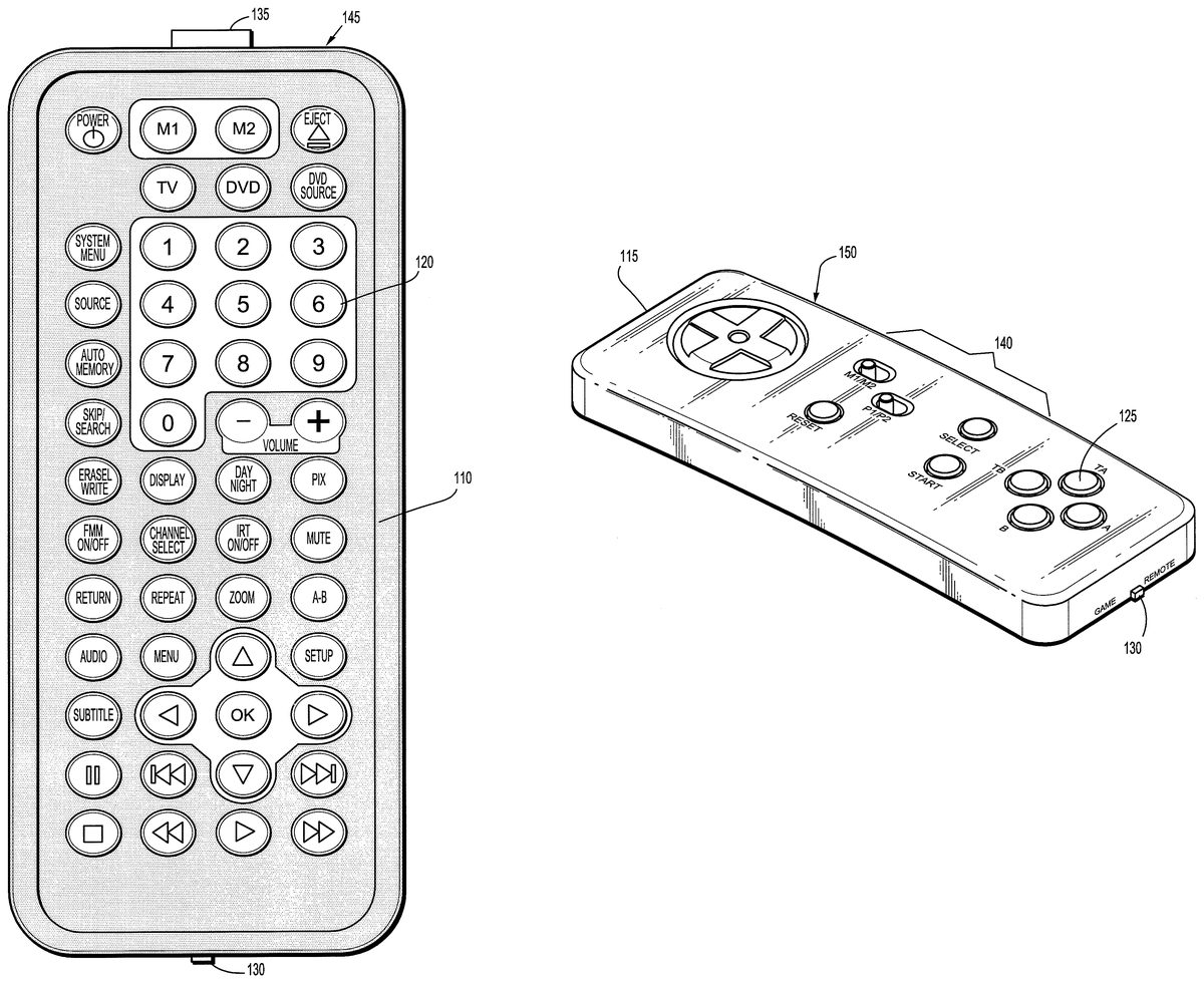
DETAILED DESCRIPTION OF EXEMPLARY EMBODIMENTS A two-sided electronic game and remote controller according to an exemplary embodiment of the present invention will now be discussed. It is to be understood that although the following discussion will center on using the controller as part of an in-vehicle entertainment system, the controller can be used with any in-flight entertainment system or any entertainment system that provides both a digital video disc (DVD) player and video games, for example. The two-sided electronic game and remote controller discussed herein combines the functionality of two separate remote control devices into a single device. In particular, the controller combines the functionality of both a video game controller and a conventional television (TV)/DVD remote controller into a single hand-held device that contains all the required components and batteries for power, for example. One side of the device contains the remote control buttons, while the opposite side of the device contains the game control buttons. Thus, instead of picking up one unit, using it, placing it down, picking up another unit and using it, one merely has to flip the same unit from one side to the other side to use it. By designing a controller like this, an in-vehicle entertainment system having both TV/DVD and video gaming capability requires only one remote, thereby reducing vehicle clutter and the cost associated with manufacturing such a product, for example. FIG. 1Aillustrates one side of a two-sided electronic game and remote controller according to an exemplary embodiment of the present invention.FIG. 1Bis a perspective view of the controller shown inFIG. 1Amostly illustrating its other side. As shown inFIGS. 1A and 1B, the controller is formed from a housing that includes a first elongated side110and a second elongated side115. The first side110is opposite the second side115. The first side110includes a plurality ...
DETAILED DESCRIPTION OF EXEMPLARY EMBODIMENTS
A two-sided electronic game and remote controller according to an exemplary embodiment of the present invention will now be discussed. It is to be understood that although the following discussion will center on using the controller as part of an in-vehicle entertainment system, the controller can be used with any in-flight entertainment system or any entertainment system that provides both a digital video disc (DVD) player and video games, for example.
The two-sided electronic game and remote controller discussed herein combines the functionality of two separate remote control devices into a single device. In particular, the controller combines the functionality of both a video game controller and a conventional television (TV)/DVD remote controller into a single hand-held device that contains all the required components and batteries for power, for example. One side of the device contains the remote control buttons, while the opposite side of the device contains the game control buttons. Thus, instead of picking up one unit, using it, placing it down, picking up another unit and using it, one merely has to flip the same unit from one side to the other side to use it. By designing a controller like this, an in-vehicle entertainment system having both TV/DVD and video gaming capability requires only one remote, thereby reducing vehicle clutter and the cost associated with manufacturing such a product, for example.
FIG. 1Aillustrates one side of a two-sided electronic game and remote controller according to an exemplary embodiment of the present invention.FIG. 1Bis a perspective view of the controller shown inFIG. 1Amostly illustrating its other side.
As shown inFIGS. 1A and 1B, the controller is formed from a housing that includes a first elongated side110and a second elongated side115. The first side110is opposite the second side115.
The first side110includes a plurality of user-operable switches120. The switches120enable a user to control an in-vehicle entertainment system205(seeFIG. 2). The second side115also includes a plurality of user-operable switches125. The switches125enable a user to play video games on the in-vehicle entertainment system205. The switches120and125may be push-button, single-pole double-throw and rocker type switches, for example.
The housing also includes a switch130for putting the controller in a remote mode or a game mode. The switch130may be a push-button or single-pole double-throw type switch, for example. When the controller is put in the remote mode, certain components of the in-vehicle entertainment system205such as a TV or a DVD player can be operated, whereas, when the controller is put in the game mode, video games can be played on the in-vehicle entertainment system205, for example. In addition, when the controller is in the remote mode, the switches120on the first side110are operable and the switches125on the second side115are not operable. Also, when the controller is in the game mode, the switches125on the second side115are operable and the switches120on the first side110are not operable.
The housing further includes dedicated remote mode and game mode transmitters215and220(seeFIG. 2). The transmitters215and220maybe infrared (IR) diode type or radio frequency (RF) type, for example. The housing also includes transparent portions135and140, located at an end side145and a lengthwise side150thereof. The transparent portions135and140permit the transmitters215and220to emit signals therethrough, respectively.
As shown inFIG. 1A, the transparent portion135is situated at the end side145so that the transparent portion135can be directed towards a display device of the in-vehicle entertainment system205when a user is operating the switches120on the first side110, thereby enabling a beam emitted by the transmitter215to be directly transmitted to the display device. As shown inFIG. 1B, the transparent portion140is situated at the lengthwise side150so that the transparent portion140can be directed towards a display device of the in-vehicle entertainment system205when a user is operating the switches125on the second side115thereby enabling a beam emitted by the transmitter220to be directly transmitted to the display device.
FIG. 2is a block diagram that illustrates a two-sided electronic game and remote controller210according to an exemplary embodiment of the present invention, and the in-vehicle entertainment unit205.
As shown inFIG. 2, the controller210includes the dedicated remote mode and game mode transmitters215and220, a central processing unit (CPU)225, remote and game inputs230and235, a game/remote switch240and a communications bus245. The remote and game inputs230and235are analogous to the user-operable switches120and125, respectively. The game/remote switch240is analogous to the switch130.
The CPU225communicates with the components of the controller210over the communication bus245. Also included in the controller210is a memory, either part of the CPU225or separate from the CPU225, which may be any kind of programmable memory for implementing default controller210functions such as input and output processing, scoring functions, timer function, etc. as appropriate to the particular controller210implementation. In an example operation of the controller210, when in the remote mode, upon receiving instructions via the remote input230, the transmitter215wirelessly transmits these instructions to a DVD player of the in-vehicle entertainment system205. A control program present in the DVD player causes the transmitted instructions to be effectuated. For example, the control program causes a DVD to be played so that it can be viewed on a display of the in-vehicle entertainment system205.
It is to be understood that the in-vehicle entertainment system205my be a 12 volt direct current mobile video rear vehicle seat entertainment system (mounted on the vehicle's ceiling, in the vehicle's headrests or on the vehicle's center console). The electronic games can be embedded in the system's electronics. The electronic games may be single or double player games. The choice between a single or double player game can be made at the controller210. The in-vehicle entertainment system205may also include a TV tuner for enabling TV to be watched on the system's display. The in-vehicle entertainment system205may further include other audio/visual entertainment features such as compact disc (CD), Moving Pictures Expert Group-1, Audio Layer 3 (MP3), Windows Media Audio (WMA), Universal Serial Bus (USB), surround sound, etc.
It is to be understood that the above description is only representative of illustrative embodiments. For the convenience of the reader, the above description has focused on a representative sample of possible embodiments, a sample that is illustrative of the principles of the invention. The description has not attempted to exhaustively enumerate all possible variations. That alternative embodiments may not have been presented for a specific portion of the invention, or that further undescribed alternatives may be available for a portion, is not to be considered a disclaimer of those alternate embodiments. Other applications and embodiments can be implemented without departing from the spirit and scope of the present invention.
It is therefore intended, that the invention not be limited to the specifically described embodiments, because numerous permutations and combinations of the above and implementations involving non-inventive substitutions for the above can be created, but the invention is to be defined in accordance with the claims that follow. It can be appreciated that many of those undescribed embodiments are within the literal scope of the following claims, and that others are equivalent.
Claims
- A remote control device, comprising: a housing having first and second elongated sides opposite each other, the first side including a plurality of user-operable switches for controlling a display device, and the second side including a plurality of user-operable switches for enabling a user to play a video game on the display device, the housing further having a pair of lengthwise sides disposed between the first and second elongated sides and a pair of end sides disposed between the first and second elongated sides, wherein a remote mode transmitter is disposed at one of the end sides and a game mode transmitter is disposed at one of the lengthwise sides.
- The remote control device of claim 1 , the housing further comprising: a switch for putting the remote control device in a remote mode or a game mode.
- The remote control device of claim 2 , wherein when the remote control device is in the remote mode, the user-operable switches on the first side operate and the user-operable switches on the second side do not operate;and when the remote control device is in the game mode, the user-operable switches on the second side operate and the user-operable switches on the first side do not operate.
- The remote control device of claim 1 , wherein the remote mode transmitter is an infrared (IR) diode.
- The remote control device of claim 1 , wherein the game mode transmitter is an IR diode.
- A remote control device, comprising: a housing having top and bottom sides, a pair of end sides between the top and bottom sides and a pair of lengthwise sides between the top and bottom sides, the top side having a plurality of user-operable switches for controlling a display device, the bottom side having a plurality of user-operable switches for enabling a user to play a video game on the display device, one of the end sides having a switch for setting an operating mode of the remote control device, the other end side having a transparent portion to permit a first transmitter to emit a beam of light therethrough, and one of the lengthwise sides having a transparent portion to permit a second transmitter to emit a beam of light therethrough.
- The remote control device of claim 6 , wherein the transparent portion of the end side is configured so that it is facing the display device when a user is operating the switches on the top side.
- The remote control device of claim 6 , wherein the transparent portion of the lengthwise side is configured so that it is facing the display device when a user is operating the switches on the bottom side.
- A remote control device for use with an in-vehicle entertainment system, comprising: a housing having first and second elongated sides opposite each other, the first side including a plurality of user-operable switches for controlling a television (TV) or a digital video disc (DVD) player of an in-vehicle entertainment system, and the second side including a plurality of user-operable switches for enabling a user to play a video game on the in-vehicle entertainment system, the housing further having a pair of lengthwise sides disposed between the first and second elongated sides and a pair of end sides disposed between the first and second elongated sides, wherein a first mode transmitter is disposed at one of the end sides and a second mode transmitter is disposed at one of the lengthwise sides.
- The remote control device of claim 9 , wherein the in-vehicle entertainment system is a headrest entertainment system.
- The remote control device of claim 9 , wherein the in-vehicle entertainment system is an overhead entertainment system.
- The remote control device of claim 9 , wherein the in-vehicle entertainment system is a console entertainment system.
- The remote control device of claim 9 , wherein the user-operable switches on the first side further control compact disc (CD), Moving Pictures Expert Group-1, Audio Layer 3 (MP3), Windows Media Audio (WMA), Universal Serial Bus (USB), or surround sound of the in-vehicle entertainment system.
- The remote control device of claim 9 , the housing further comprising: a switch for changing an operating mode of the remote control device.
- The remote control device of claim 14 , the housing further comprising: the first mode transmitter configured for transmitting signals input via the user-operable switches on the first side to the in-vehicle entertainment system when the remote control device is in a first operating mode.
- The remote control device of claim 15 , the housing further comprising: the second mode transmitter configured for transmitting signals input via the user-operable switches on the second side to the in-vehicle entertainment system when the remote control device is in a second operating mode.
- The remote control device of claim 16 , wherein the housing is flipped from the first side to the second side when the operating mode is changed from the first to the second.
- The remote control device of claim 16 , wherein the housing is flipped from the second side to the first side when the operating mode is changed from the second to the first.
Disclaimer: Data collected from the USPTO and may be malformed, incomplete, and/or otherwise inaccurate.